YORKVILLE LS801P Manuel utilisateur
- Catégorie
- Équipement musical supplémentaire
- Taper
- Manuel utilisateur

SERVICE MANUAL
LS801P
SMT Disclaimer
Due to the complex nature of the use of SMT installed components
in Yorkville equipment, we highly caution all service technicians in
attempting to repair or replace SMT factory installed components.
Many of these components may be glued prior to initial soldering.
Replacing SMT components requires expensive
specialized de-soldering equipment and training.
Yorkville Sound will repair and replace defective SMT components
to ensure proper quality assurance and installation is maintained.
U.S.A.
Yorkville Sound Inc.
4625 Witmer Industrial Estate
Niagara Falls, New York
14305, USA
Voice: 716-297-2920
Fax: 716-297-3689
WORLD HEADQUARTERS
CANADA
Yorkville Sound Limited
550 Granite Court
Pickering, Ontario
L1W 3Y8 CANADA
Voice: 905-837-8481
Fax: 905-837-8746
Manual-Service-LS801P-00-2v3 • July 19, 2018

The exclamation point within an equilatereal triangle is intended to alert the
user to the presence of important operating and maintenance (servicing)
instructions in the literature accompanying the appliance.
Le point d’exclamation à l’intérieur d’un triangle équilatéral est prévu pour alerter
l’utilisateur de la présence d’instructions importantes dans la littérature accompagnant
l’appareil en ce qui concerne l’opération et la maintenance de cet appareil.
This lightning flash with arrowhead symbol, within
an equilateral triangle, is intended to alert the user to the presence of
uninsulated “dangerous voltage” within the product’s enclosure that may be
of sufficient magnitude to constitute a risk of electric shock to persons.
Ce symbole d’éclair avec tête de flèche dans un triangle équilatéral est prévu pour alerter
l’utilisateur de la présence d’un «voltage dangereux» non-isolé à proximité de l’enceinte du
produit qui pourrait être d’ampleur suffisante pour présenter un risque de choque électrique.
DOC-Safety-5v0+UL60065-00-1v2 • May 31, 2018
CAUTION: TO REDUCE THE RISK OF ELECTRIC SHOCK,
DO NOT REMOVE COVER (OR BACK).
NO USER SERVICEABLE PARTS INSIDE.
REFER SERVICING TO QUALIFIED SERVICE PERSONNEL.
THIS DEVICE IS FOR INDOOR USE ONLY!
Instructions pertaining to a risk of fire, electric shock, or injury to a person
Read Instructions: The Owner’s Manual should be read and understood before operation of your unit. Please, save these
instructions for future reference and heed all warnings.
Clean only with dry cloth.
Packaging: Keep the box and packaging materials, in case the unit needs to be returned for service.
Warning: To reduce the risk or fire or electric shock, do not expose this apparatus to rain or moisture. Do not
use this apparatus near water!
Warning: When using electric products, basic precautions should always be followed, including the following:
Power Sources
Your unit should be connected to a power source only of the voltage specified in the owners manual or as marked on the
unit. This unit has a polarized plug. Do not use with an extension cord or receptacle unless the plug can be fully inserted.
Precautions should be taken so that the grounding scheme on the unit is not defeated. An apparatus with CLASS I
construction shall be connected to a Mains socket outlet with a protective earthing ground. Where the MAINS plug or an
appliance coupler is used as the disconnect device, the disconnect device shall remain readily operable.
Hazards
Do not place this product on an unstable cart, stand, tripod, bracket or table. The product may fall, causing serious personal
injury and serious damage to the product. Use only with cart, stand, tripod, bracket, or table recommended by the
manufacturer or sold with the product. Follow the manufacturer’s instructions when installing the product and use mounting
accessories recommended by the manufacturer. Only use attachments/accessories specified by the manufacturer
Note: Prolonged use of headphones at a high volume may cause health damage on your ears.
The apparatus should not be exposed to dripping or splashing water; no objects filled with liquids should be
placed on the apparatus.
Terminals marked with the “lightning bolt” are hazardous live; the external wiring connected to these terminals require
installation by an instructed person or the use of ready made leads or cords.
Ensure that proper ventilation is provided around the appliance. Do not install near any heat sources such as radiators,
heat registers, stoves, or other apparatus (including amplifiers) that produce heat.
No naked flame sources, such as lighted candles, should be placed on the apparatus.
Power Cord
Do not defeat the safety purpose of the polarized or grounding-type plug. A polarized plug has two blades with one wider than the
other. A grounding type plug has two blades and a third grounding prong. The wide blade or the third prong are provided for your
safety. If the provided plug does not fit into your outlet, consult an electrician for replacement of the obsolete outlet. The AC supply
cord should be routed so that it is unlikely that it will be damaged. Protect the power cord from being walked on or pinched particularly
at plugs. If the AC supply cord is damaged DO NOT OPERATE THE UNIT. To completely disconnect this apparatus from the AC
Mains, disconnect the power supply cord plug from the AC receptacle. The mains plug of the power supply cord shall remain readily
operable.
Unplug this apparatus during lightning storms or when unused for long periods of time.
Service
The unit should be serviced only by qualified service personnel. Servicing is required when the apparatus has been damaged in
any way, such as power-supply cord or plug is damaged, liquid has been spilled or objects have fallen into the apparatus, the
apparatus has been exposed to rain or moisture, does not operate normally, or has been dropped.
AVIS: AFIN DE REDUIRE LES RISQUE DE CHOC ELECTRIQUE, N’ENLEVEZ PAS LE COUVERT
(OU LE PANNEAU ARRIERE)
NE CONTIENT AUCUNE PIECE REPARABLE PAR L’UTILISATEUR.
CONSULTEZ UN TECHNICIEN QUALIFIE POUR L’ENTRETIENT
CE PRODUIT EST POUR L’USAGE À L’INTÉREUR SEULEMENT
Instructions relatives au risque de feu, choc électrique, ou blessures aux personnes
Veuillez Lire le Manuel: Il contient des informations qui devraient êtres comprises avant l’opération de votre appareil.
Conservez. Gardez S.V.P. ces instructions pour consultations ultérieures et observez tous les avertissements.
Nettoyez seulement avec le tissu sec.
Emballage: Conservez la boite au cas ou l’appareil devait être retourner pour réparation.
Avertissement: Pour réduire le risque de feu ou la décharge électrique, n'exposez pas cet appareil à la pluie ou à l'humidité.
N’utilisez pas cet appareil près de l’eau!
Attention: Lors de l’utilisation de produits électrique, assurez-vous d’adhérer à des précautions de bases incluant celle qui suivent:
Alimentation
L’appareil ne doit être branché qu’à une source d’alimentation correspondant au voltage spécifié dans le manuel ou tel
qu’indiqué sur l’appareil. Cet appareil est équipé d’une prise d’alimentation polarisée. Ne pas utiliser cet appareil avec un
cordon de raccordement à moins qu’il soit possible d’insérer complètement les trois lames. Des précautions doivent êtres
prises afin d’eviter que le système de mise à la terre de l’appareil ne soit désengagé. Un appareil construit selon les normes
de CLASS I devrait être raccordé à une prise murale d’alimentation avec connexion intacte de mise à la masse. Lorsqu’une
prise de branchement ou un coupleur d'appareils est utilisée comme dispositif de débranchement, ce dispositif de
débranchement devra demeurer pleinement fonctionnel avec raccordement à la masse.
Risque
Ne pas placer cet appareil sur un chariot, un support, un trépied ou une table instables. L’appareil pourrait tomber et blesser
quelqu’un ou subir des dommages importants. Utiliser seulement un chariot, un support, un trépied ou une table
recommandés par le fabricant ou vendus avec le produit. Suivre les instructions du fabricant pour installer l’appareil et utiliser
les accessoires recommandés par le fabricant. Utilisez seulement les attachements/accessoires indiqués par le fabricant
Note: L'utilisation prolongée des écouteurs à un volume élevé peut avoir des conséquences néfastes sur la santé
sur vos oreilles. .
Il convient de ne pas placer sur l’appareil de sources de flammes nues, telles que des bougies allumées.
L’appeil ne doit pas être exposé à des égouttements d’eau ou des éclaboussures et qu’aucun objet rempli de liquide tel
que des vases ne doit être placé sur l’appareil.
Assurez que lappareil est fourni de la propre ventilation. Ne procédez pas à l’installation près de source de chaleur tels
que radiateurs, registre de chaleur, fours ou autres appareils (incluant les amplificateurs) qui produisent de la chaleur.
Les dispositifs marqués d’une symbole “d’éclair” sont des parties dangereuses au toucher et que les câblages
extérieurs connectés à ces dispositifs de connection extérieure doivent être effectivés par un opérateur formé ou en
utilisant des cordons déjà préparés.
Cordon d’Alimentation
Ne pas enlever le dispositif de sécurité sur la prise polarisée ou la prise avec tige de mise à la masse du cordon d’alimentation.
Une prise polarisée dispose de deux lames dont une plus large que l’autre. Une prise avec tige de mise à la masse dispose de
deux lames en plus d’une troisième tige qui connecte à la masse. La lame plus large ou la tige de mise à la masse est prévu
pour votre sécurité. La prise murale est désuète si elle n’est pas conçue pour accepter ce type de prise avec dispositif de
sécurité. Dans ce cas, contactez un électricien pour faire remplacer la prise murale. Évitez d’endommager le cordon
d’alimentation. Protégez le cordon d’alimentation. Assurez-vous qu’on ne marche pas dessus et qu’on ne le pince pas en
particulier aux prises. N’UTILISEZ PAS L’APPAREIL si le cordon d’alimentation est endommagé. Pour débrancher
complètement cet appareil de l’alimentation CA principale, déconnectez le cordon d’alimentation de la prise d’alimentation
murale. Le cordon d’alimentation du bloc d’alimentation de l’appareil doit demeurer pleinement fonctionnel.
Débranchez cet appareil durant les orages ou si inutilisé pendant de longues périodes.
Service
Consultez un technicien qualifié pour l’entretien de votre appareil. L'entretien est nécessaire quand l'appareil a été endommagé de
quelque façon que se soit. Par exemple si le cordon d’alimentation ou la prise du cordon sont endommagés, si il y a eu du liquide
qui a été renversé à l’intérieur ou des objets sont tombés dans l'appareil, si l'appareil a été exposé à la pluie ou à l'humidité, si il ne
fonctionne pas normalement, ou a été échappé.
S2125A
CAUTION: HOT SURFACE
ATTENTION: SURFACE CHAUDE
IEC 60417-5041
IMPORTANT SAFETY INSTRUCTIONS
IMPORTANT SAFETY INSTRUCTIONS (UL60065)
FOLLOW ALL INSTRUCTIONS SUIVEZ TOUTES LES INSTRUCTIONS
The Lightning Flash with arrowhead symbol within an equilateral triangle, is intended to alert the user to the presence of uninsulated
"dangerous voltage" within the product enclosure that may be of sufficient magnitude to constitute a risk of shock to persons
The exclamation point within an equilateral triangle is intended to alert the user to the presence of important operating and maintenance
(servicing) instructions in the literature accompanying the product
1. Read these instructions.
2. Keep these instructions.
3. Heed all warnings.
4. Follow all instructions.
5. Do not use this apparatus near water.
6. Clean only with dry cloth.
7. Do not block any ventilation openings. Install in accordance with the manufacturer’s instructions.
8. Do not install near any heat sources such as radiators, heat registers, stoves, or other apparatus (including amplifiers) that produce heat.
9. Do not defeat the safety purpose of the polarized or grounding-type plug. A polarized plug has two blades with one wider than the other. A
grounding type plug has two blades and a third grounding prong. The wide blade or the third prongs are provided for your safety. If the provided
plug does not fit into your outlet, consult an electrician for replacement of the obsolete outlet.
10. Protect the power cord from being walked on or pinched particularly at plugs, convenience receptacles, and the point where they exit
from the apparatus.
11. Only use attachments/accessories specified by the manufacturer.
12. Use only with the cart, stand, tripod, bracket, or table specified by the manufacturer, or sold with the apparatus. When a cart is used, use caution
when moving the cart/apparatus combination to avoid injury from tip-over.
13. Unplug this apparatus during lightning storms or when unused for long periods of time.
14. Refer all servicing to qualified service personnel. Servicing is required when the apparatus has been damaged in any way, such as
power-supply cord or plug is damaged, liquid has been spilled or objects have fallen into the apparatus, the apparatus has been exposed to rain or
moisture, does not operate normally, or has been dropped.
WARNING:
• To reduce the risk of fire or electric shock, do not expose this apparatus to rain or moisture and objects filled with liquids, such as vases, should not be
placed on this apparatus.
• To completely disconnect this apparatus from the ac mains, disconnect the power supply cord plug from the ac receptacle.
• The mains plug of the power supply cord or appliance coupler shall remain readily accessible.
Le symbole représentant un éclair avec une flèche à l’intérieur d’un triangle équilatéral est utilisé pour prévenir l’utilisateur de la
présence d’une tension électrique dangereuse non isolée à l’intérieur de l’appareil. Cette tension est d’un niveau suffisamment
élevé pour représenter un risque d’électrocution
Le symbole représentant un point d’exclamation à l’intérieur d’un triangle équilatéral, signale à l’utilisateur la présence d’instructions
importantes relatives au fonctionnement et à l’entretien de l’appareil dans cette notice d’installation
1. Lisez ces instructions.
2. Conservez ces instructions.
3. Respecter tous les avertissements.
4. Suivez toutes les instructions.
5. N'utilisez pas l'appareil près de l'eau.
6. Nettoyer uniquement avec chiffon sec.
7. Ne bloquez pas les ouvertures de ventilation. Installer en suivant les instructions du fabricant.
8. Ne pas installer près des sources de chaleur telles que radiateurs, bouches de chaleur, four ou autres appareils (y compris les amplificateurs)
produisant de la chaleur.
9. N'annulez pas l'objectif sécuritaire de la fiche polarisée ou de la tige de mise à la terre. Une fiche polarisée possède deux lames avec une plus
large que l'autre. Une prise avec mise à la terre possède deux lames et une troisième tige. La lame large ou la troisième tige sont fournis pour
votre sécurité. Si la fiche n'entre pas dans votre prise, consultez un électricien pour remplacer la prise obsolète.
10. Protéger le cordon d'alimentation des piétinements ou pincements en particulier près des fiches, des prises de courant et au point de
sortie de l'appareil.
11. Utilisez uniquement les accessoires spécifiés par le fabricant.
12. Utiliser uniquement avec un charriot, stand, trépied ou une table spécifiée par le fabricant, ou vendus avec l'appareil.
13. Débranchez l'appareil durant un orage ou lorsqu'il reste inutilisé pendant de longues périodes de temps.
14. Confiez toute réparation à un technicien qualifié. Une réparation est nécessaire lorsque l'appareil a été endommagé de quelque façon que ce
soit; comme lorsque le cordon d'alimentation ou la fiche est endommagé, lorsque du liquide a été renversé ou des objets sont tombés à l'intérieur,
lorsque l'appareil a été exposé à la pluie ou l'humidité, ne fonctionne pas normalement, ou est tombé.
AVERTISSEMENT:
• Pour réduire les risques d'incendie ou de choc électrique, ne pas exposer cet appareil à la pluie ou à l'humidité et ne placez pas d’objets contenant
des liquides, tels que des vases, sur l’appareil.
• Pour isoler totalement cet appareil de l'alimentation secteur, débranchez totalement son cordon d'alimentation du réceptacle CA.
• La prise du cordon d’alimentation ou du prolongateur, si vous en utilisez un comme dispositif de débranchement, doit rester facilement accessible
CAUTION
TO PREVENT ELECTRIC SHOCK HAZARD,
DO NOT CONNECT TO MAINS POWER SUPPLY
WHILE GRILLE IS REMOVED.
AVIS
POUR PRÉVENIR LES RISQUES D'ÉLECTROCUTION,
NE PAS RACCORDER A L’ALIMENTATION ÉLECTRIQUE ALORS
QUE LA GRILLE EST RETIRÉE.

POWER
ON
PUSH
TO RESET
OFF
LS801P
Yorkville
1500 WATT ACTIVE SUBWOOFER ENCLOSURE
STEREO ACTIVE SPEAKER CONFIGURATION
STEREO PASSIVE SPEAKER CONFIGURATION
MONO BLEND*
INPUT
1
3
2
1
3
2
2
3
1
LS801P
LEVEL
LINE / SPKR
SHAPE
DEEPLOUD
HF ROLLOFF
15090
NOTES:
ALL LINK CONNECTIONS FUNCTION AS INPUTS OR OUTPUTS.
MONO BLEND INPUT IS DESIGNED TO PROPERLY SUM TWO LINE SOURCES
SUCH AS TWO CHANNELS FROM A MIXER OR A STEREO SOURCE
*
*
INPUT Switch set to LINE
*
INPUT Switch set to LINE
*
INPUT Switch set to SPKR
MIXER
MIXER
PWR
AMP
LS801P
LS801P #1 LS801P #2
STEREO ACTIVE SPEAKER CONFIGURATION
LS801P #1 LS801P #2
DESIGNED & MANUFACTURED BY
YORKVILLE SOUND • TORONTO, CANADA
TYPE: YS1023 : E60 Z1183 / 1v2
230V
50Hz 3,3A
120VAC
60Hz 6.6A
MONO BLEND INPUT INPUT INPUTOUTPUT OUTPUT
CLIP
POWER
LIMIT
15090DEEPLOUD
Hz
LS801P
LEVEL
SHAPE
HI FREQ.
ROLLOFF
12
dB
INPUT
LINE
SPKR

Specifications
System Type
Rear Horn Loaded Subwoofer
Active or Passive
Active
Program Power (Watts)
1500
Max SPL (dB)
134
Frequency Response (Hz +/- 3db)
45 - 150
LF Driver(s)
Single 18 inch w/ 4 inch voicecoil
LF Program Power(Watts)
1500
LF Protection
Thermal / Overcurrent / Clip
Power Consumption (typ/max)
120V (6.6A / 7.5), 230V (3.3A / 3.9)
Inputs - 1/4-inch Jacks
2 line/speaker level inputs, 2 link (in/out)
Inputs - XLR
2 line inputs, 2 link (in/out)
Level Controls
Master
Bar Handles
2 Side
Pole Mount Adapter (1 3/8-inch-3.5cm)
1 Top
Enclosure Materials
3/4 inch 7-ply Spruce
Grille
Perforated Metal
Covering / Finish
Black Ozite (Carpet)
Optional Covering / Finishes
Black Ultrathane Paint (LS801PB) 15mm 11-ply Birch
Dimensions (DWH xbackW, inches)
23 x 27.5 x 32
Dimensions (DWH xbackW, cm)
58.4 x 70 x 81.3
Weight (lbs/kg)
143 / 65

Spécifications
Type de système
Subwoofer à pavillon monté par l’arrière
Acti
ve
ou Passi
ve
Active
Puissance Nominale (Watts)
1500
Niveau de Pression Sonore Max (dB)
134
Réponse en Fréquence (Hz +/- 3db)
45 – 150
Driver(s) Graves
Un HP 18 pouces avec bobine mobile de 4 pouces
Puissance Nominale fréquences Graves (Watts)
1500
Protection Fréquence Graves
Thermique / Surcharge de courant / Écrêtage
Consommation de Puissance (typ/max)
120V (6.6A / 7.5), 230V (3.3A / 3.9)
Entrées - 1/4-pouce Jacks
2 entrées niveau ligne/HP, 2 link (entrée/sortie)
Entrées - XLR
2 entrées lignes, 2 link (entrées/sortie)
Contrôles de Niveau
Principale
Poignées
2 côtés
Adaptateur pour montage sur poteau
(1 3/8-pouce-3.5cm)
1 Dessus
Matériaux
3/4 pouce 7-plis épinette
Grille
Métal Perforé
Recouvrement/ Finition
Tapis Noire
Recouvrement Optionel / Finition
Peinture Noire Ultrathane (LS801PB) 15mm 11-plis Bouleau
Dimensions (PLH x L arrière, pouces)
23 x 27.5 x 32
Dimensions (PLH x L arrière, cm)
58.4 x 70 x 81.3
Poids (livres/kg)
143 / 65

MONO BLEND*
INPUT
1
3
2
1
3
2
2
3
1
LS801P
LEVEL
LINE / SPKR
SHAPE
DEEPLOUD
HF ROLLOFF
15090
*
NOTES:
ALL LINK CONNECTIONS FUNCTION AS INPUTS OR OUTPUTS.
MONO BLEND INPUT IS DESIGNED TO PROPERLY SUM TWO LINE SOURCES
SUCH AS TWO CHANNELS FROM A MIXER OR A STEREO SOURCE
Block-Diag-LS801P-00-1v1.ai
PRODUCT TYPE: YS1023: E60
Block Diagram for LS801P
DESIGNED & MANUFA CTURED BY YORKVILLE SOUND

LS801P Parts List 7/19/2018
YS # Description Qty. YS # Description Qty. YS # Description Qty.
5221 470P 1000V 5%CAP POLYPROP BULK 1 7967 _15.0UH COIL 0805 SMT 5 7627 W100 13K 1% 0805 SMT RES 1
6451 __4N7 250V 20%CAP BLK 'Y' 10MM AC 1 8152 220UH COIL 10X10MM SMT 1 7628 W100 15K0 1% 0805 SMT RES 1
5212 100N 63V 5%CAP T&R RAD .2FLM 4 2906 486UH COIL COMMON MODE 8A SMT 1 7634 W100 20K5 1% 0805 SMT RES 1
5242 100N 250V 20%CAP BLK 'X2' 15MM AC 1 7974 1000UH 10% COIL 12MM SMT 1 5066 W125 22K1 1% 0805 SMT RES 2
5972 680N 400V 5%CAP BLK RAD POLY FLM 2 8253 20P 100V 5%CAP 0805 SMT NPO 3 5067 W125 31K6 0.1% 0805 SMT RES 4
5266 680N 250V 20%CAP BLK 'X2' 27MM AC 1 7813 _47P 50V 5%CAP 0805 SMT NPO 1 8027 W125 37K4 1% 0805 SMT RES 1
5256 __1U 63V 5%CAP T&R RAD .2FLM 2 5982 150P 1000V 5%CAP 1206 SMT C0G 2 8135 W125 47K 5% 0805 SMT RES 2
5962 __2U2 140AC10%CAP BLK RAD POLYP FLM 2 7871 470P 50V 5%CAP 0603 SMT NPO 2 7824 W125 47K5 1% 0805 SMT RES 1
5951 __3U3 450DC10%CAP BLK MPOLYP FLM 1 8178 470P 250V 5%CAP 0603 SMT NP0 3 7703 W125 82K5 1% 0805 SMT RES 2
5945 _10U 63V 20%CAP T&R RAD .2EL 2 7603 680P 50V 5%CAP 0805 SMT C0G 1 7864 W125 100K 5% 0805 SMT RES 4
5669 470U 6V3 20%CAP RAD EL T&R 1 7693 __1N 50V 5%CAP 0805 SMT NPO 1 7864 W125 100K 5% 0805 SMT RES 1
5887 2200U 50V 20%CAP BLK 18X27MM EL 2 8176 _47N 100V 10%CAP 1206 SMT X7R 1 7630 W100 182K 1% 0805 SMT RES 3
5934 2700U 250V 20%CAP BLK 40X60MM 4PS 4 7767 100N 16V 10%CAP 0603 SMT X7R 20 5068 W125 187K 0.1% 0805 SMT RES 2
2339 _10K B LIN 12MM DUAL 21DET P34 1 7875 100N 100V 10%CAP 1206 SMT X7R 21 7686 W100 274K 1% 0805 SMT RES 2
4526 _10K TRIM POT 6MM TOP ADJ RAD 4 7601 220N 50V 10%CAP 1206 SMT X7R 1 7622 W100 1M0 1% 0805 SMT RES 2
6405 RED 3MM LED 2V1 20MA DIFFUSD 1 7736 470N 50V 5%CAP 1206 SMT X7R 1 7688 W125 4M7 5% 0805 SMT RES 1
6400 YEL 3MM LED 2V1 20MA DIFFUSD 2 7878 __1U 25V 20%CAP 1206 SMT X7R 4 4931 470K 5% THERMISTOR NTC 0805 SMT 1
6408 GRN 3MM LED 2V2 20MA DIFFUSD 2 7878 __1U 25V 20%CAP 1206 SMT X7R 12 8165 MMBTA92 PNP SOT-23 SMT 2
6554 BLUE 3MM LED 3V9 20MA 1 7886 __4U7 25V 20%CAP 4X5.5 SMT ELC 4 7806 MMBF4391LT1 NCH JFET SOT-23 SMT T&R 1
6775 BRIDGE 25A 600V WIRE LEAD SIP 1 7969 _10U 10V 20%CAP 0805 SMT Y5V 2 8002 TEST POINT MINIATURE SMT 11
6857 NJM7915FA TO220 N 15V0 REG IS V2 2 7969 _10U 10V 20%CAP 0805 SMT Y5V 1 4088 RECEPTACLE:V-LOCK INLET 1
7012 LP2950-33 LDRP TO92 FIXED 3V3 REG 2 7917 _33U 25V 20%CAP 6.3X5.5 SMT EL 1 3749 3/8X.170ID.31OD NYLON SPACER 9
2307 IRGP35B60PDPBF T0247 NPN IGBT TM 2 7811 100U 25V 20%CAP 8X5.4 SMT ELE 1 8665 .5X.145ID.25OD ALUM SPACER 4
6668 LTV-8141S ACINPUT OPTOCOUPLER SMT 1 7750 CDSF4148 75V 0A15 1005 SMT 5 8681 4-40 X .940" ALUMINUM HEX SPACER 3
6543 48R 265V RESETTABLE THERMISTOR PTC 1 9106 BAT750 SOT-23 SMT SCHTKY 19 8657 6-32X3/8 ALUM HEX SPACER 1
2455 METAL HEX NUT 3/8-24 (USE W/ 2454) 2 7617 BZX84C15LT1 15V0 0W225 ZEN SOT23 1 7420 18" 8R 1200WPGM SPEAKER 1
2491 10.00 AMP CIRCUIT BREAKER TE 1 7832 MM3Z18VT1G 18V0 0W2 5% SMT ZEN 1 8482 3/8 1D FLAT WASHER 2
X8024BLANK 2_OZ 2SD 83.13SQIN 1PER ELITE PSA 1 7832 MM3Z18VT1G 18V0 0W2 5% SMT ZEN 2 3501 #4 B52200F006 COMP WASH SMALL 2
6663 _533UH CHOKE 120T19AWG/77908MAGNTKS 1 8164 BZX84C22 22V0 0W3 5% SMT ZEN 1 8485 #6 SPLIT WASHER ZINC 2
8579 4000 SERIES RIGID CASTER 11 7619 BZX84C43 43V0 0W3 5% SMT ZEN 1 8818 3/4ODX3/8IDX.080 THICK WASHER 1
3601 RING TERMINAL 16AWG WIRE & #8 SCREW 10 8256 FERRITE BEAD 600R @100MHZ 0805 SMT 1 4202 SP3T NONSHORTING VERT ROT SWT 3POS 2
4063 1/4IN ISO JCK PCMT VT STER RT SWT 2 7895 FUSE SLOW 7A 125V SMT 6125 2 3522 DPDT MINI PC VERT SNP ALT 2
4140 XLR MALE PCB MT VERT 24MM A-SERIES 3 6686 IRS21844SPBF IC HILO FET DRVR SO14 1 4184 DPST ROKR SW QUIK 250" AC/PWR IEC6 1
3114 PATCH 04 16AWG 34.0 PH 1 7719 MC33063ADR BUCK/BOOST INV IC SO8 2 3958 BLK 18AWG 36STND WIRE DOU/INS 2.541
2328 8 CIR XH-HEADER 0.098IN 1 8211 LNK302G OFFLINE SWITCH SMT SMD8B 1 CH1423U XFMR:ES18P 1
2328 8 CIR XH-HEADER 0.098IN 1 8163 TL331 COMPARATOR IC SMT SOT235 3 8387 PS NEO SC41 1/16" X 0.5" X 100' ROL 5
3112 PATCH 08 22AWG 24.0 XH FLAT 1 7669 TL072 DUAL OPAMP SMT SO-8 3 9990 2" X 4" VIBRATION PAD PSA FLAT SIDE 5
8551 BAR HANDLE RIGHT ANGLE TOP LOAD 1 7817 33078 DUAL OPAMP SMT SO-8 2 ZC1611 ES PSA SERIES HEATSPREADER 1
8565TEMP BAR HANDLE ALL METAL OUT OF SPEC. 2 6667 MK10DN512VLK10 100MHZ MCU IC LQFP80 1 ZC1676 ES PSA SERIES SPACER BAR #1 1
9897 SPEAKER COVER,BLACK POLYPRO, 54" W 37.5 4183 10 CIR DUAL ROW HDR 0.05 SPC SMT 3 ZC1677 ES PSA SERIES SPACER BAR #2 1
3810 4" NYLON CABLE TIE 5 7745 W125 0R 5% 0805 SMT RES 1
4215 _4 PIN POWER VH MALE .156 10A 1 7882 W250 0R 1206 SMT RES 1
4093 CONN PLUG 2 POS. .084" V-2 FEMALE 1 5079 2W00 0R02 1% OARS SMT RES 1
4162 2 PIN POWER PIN HEADER MALE POLZED 1 7849 W250 0R27 5% 1206 SMT RES 1
4146 3 PIN POWER PIN HEADER MALE POLZED 1 7802 1W00 1R0 5% 2512 SMT RES 1
4151 4 PIN POWER PIN HEADER MALE POLZED 1 8183 1W00 2R0 1% 2512 SMT RES 2
4147 6 PIN POWER PIN HEADER MALE POLZED 2 7852 W250 10R 5% 1206 SMT RES 6
3576 SOCKET TERMINAL 14-20 AWG TAPE/REEL 2 7854 W125 47R 5% 0805 SMT RES 1
8637 ROUND PUSH BUTTON 1/4" BLK 24MM 2 7854 W125 47R 5% 0805 SMT RES 5
8653C LOW PROFILE POINTER AT 12 KNOB 3 7781 W063 49R9 1% 0603 SMT RES 1
3426 8' 3/16 SJT AC LINE CORD REMOVB-CSA 1 7624 W100 100R 1% 0805 SMT RES 1
8259D LOGO ELITE SERIES LARGE DOMED 1 7624 W100 100R 1% 0805 SMT RES 4
6663CORE 77908-A7 KOOL MU POWDER CORES 1 7671 W125 249R0 1% 0805 SMT RES 1
3817 _1.5MH COIL INPUT COM MODE 1 8213 W250 330R 5% 1206 SMT RES 1
8701 4-40 KEPS NUT ZINC 4 7856 W125 470R 5% 0805 SMT RES 2
8800 6-32 KEPS NUT ZINC 2 7856 W125 470R 5% 0805 SMT RES 1
9931 6-32 NYLON INSERT LOCK NUT 19 7673 W100 475R 1% 0805 SMT RES 1
8604 10-32 T-NUT ZINC CLEAR 8 7820 W100 499R 1% 0805 SMT RES 4
8602 1/4-20 T-NUT ZINC YELLOW 10 7621 W100 1K0 1% 0805 SMT RES 2
9977 5/16-18 NYLON INSERT LOK NUT ZN CLR 1 7675 W125 1K21 1% 0805 SMT RES 1
4181 TO220 THERMO PAD CERAMIC .080 THK 2 9107 W125 1K4 1% 0805 SMT RES 1
6664 10W0 25K 5% BLK RES 2 7858 W125 1K5 5% 0805 SMT RES 2
9070 18GA ELECTRO GALV STEEL 4'X8' SHEET 0.5 7899 W125 1K800 0.1% 0805 SMT RES 4
9001 4-40X5/16 PAN PH MS ZN W/STAR WASHR 3 7902 1W00 1K8 5% 2512 SMT RES 1
8742 4-40X3/8 PAN PH TAPTITE BO&W 1 7676 W100 2K0 1% 0805 SMT RES 4
8861 4-40X3/8 PAN PHIL MS TBZ 3 7859 W125 2K2 5% 0805 SMT RES 1
8871
4-40X5/8 PAN PHILIPS MS BO&W 2 7632 W100 2K32 1% 0805 SMT RES 1
8902 4-40X3/4 PAN PHILIPS MS TBZ 2 7637 W125 3K32 1% 0805 SMT RES 2
8801 6-32X3/8 PAN PHIL TRILOBE TBZ 2 7638 W100 3K74 1% 0805 SMT RES 1
8829 6-32 X 3/8 FLAT PHIL TAPTITE TBZ 19 8189 W125 4K02 0.1% 0805 SMT RES 2
8837 6-32X1/2 ROUND PH MS JS500 2 8189 W125 4K02 0.1% 0805 SMT RES 2
8823 6-32 X 1 PAN PHILIP TAPTITE TBZ 19 7860 W125 4K7 5% 0805 SMT RES 4
8811 #6X1X1/4 FLAT HD SQ SCKT WS ZN 71 7860 W125 4K7 5% 0805 SMT RES 1
8756 #10 X 3/4 PAN QUAD TYPE A TBZ 58 7679 W100 4K99 1% 0805 SMT RES 2
8786 10-32X11/4 PAN QUAD MS TBZ 8 7680 W100 6K98 1% 0805 SMT RES 5
8777 1/4 X 1 FLAT QUAD TYPE A TBZ 4 7680 W100 6K98 1% 0805 SMT RES 2
8928 M7-2.5X30 HEX SOCKT JOINT CONN. TBZ 8 8321 W125 8K66 1% 0805 SMT RES 1
8770 1/4-20X1 5/16 PHIL TRUSS MS TBZ 10 7625 W100 10K0 1% 0805 SMT RES 3
8780 5/16-18X3 3/4 CARRIAGE BOLT FT TBZ 1 7928 W125 10K00 0.1% 0805 SMT RES 8
7941 __8.2UH COIL 1210 SMT 2 7761 W100 12K1 1% 0603 SMT RES 2

11 11
10 10
9 9
8 8
7 7
6 6
5 5
4 4
3 3
2 2
1 1
A
A
B
B
C
C
D
D
E
E
F
F
G
G
H
H
I
I
J
J
K
K
L
L
M
M
N
N
O
O
P
P
Q
Q
of
Filename:
PCB# Sheet 11
Product
Date: Rev: YsType:YsType
M1373V300sch.sch2002
M1373
Wed Nov 10, 2010
Sheet1
V03
CROW BAR/FILTER
of
Filename:
PCB# Sheet 11
Product
Date: Rev: YsType:YsType
M1373V300sch.sch2002
M1373
Wed Nov 10, 2010
Sheet1
V03
CROW BAR/FILTER
2
W6:B 4
C6
250V10N
BLACK
1
W6:A 4
4
W6:D 4
3
W6:C 4
400V
C4
1N
1
W5:A4
2
W5:B4
RED
C5
250V10N
FROM AMP
2.7mH
L36500
275V
C2
1u0
BLACK
4
W5:D4
RED
100V
C3
10N
4080
2.0UH
L2
4080
2.0UH
L1
3
W5:C4
TO SPEAKER +
TO SPEAKER -
13
10
7
4
1
9
11
12
8
#
2
3
5
6
VER#
MODEL(S):-
DATE DESCRIPTION OF CHANGE
V
V
V
V
V
V
V
V
V
V
D
D
D
D
N
N
N
N
D
D
D
D
D
D
N
N
N
N
N
N
M1373PCB_DATABASE_HISTORY
07-JAN-2009 1.00 FIRST DESIGN
CROW BAR
09-FEB-2010 3.00 PC7993: Reduce panel to 3x5 boards
14DEC09 2.00 PC#7925 CHANGE L4, L5 FROM YS#3769 TO YS#4080

VCD
CLINCH
ORIGIN
SHORT AXIS
ORIGIN
LONG AXIS
INSERT
Pcb Mech M1373
BlankSize - 15500x7000
StepAndRepeat - X5@2900Y3@2000
2ozCopper
V3.00
2ozCopper
Top Assy V3.00
V3.00
M1373
SEE LAYOUT DOCUMENTATION
M1373
V
T
R
V
T
R
V
T
R
6500
4080
5834
5834
3538
3538
5262
4080
2.7mH
2.0UH
10N
10N
1N
10N
275V
1u0
2.0UH
V3.00M1373
EMC FILTER
Into Wave
L3
L2
C5
C6
C4C3
W6
W5
C2
L1
LOC
BEC

SEE LAYOUT DIAGRAM
V3.00M1373 PRODUCTION NOTES
12
9
6
3
#
13
11
10
5
4
8
7
2
1
DATE
MODEL(S):-
VER# DESCRIPTION OF CHANGE
D
D
D
V
V
V
N
N
N
D
D
D
D
D
D
D
V
V
V
V
V
V
V
1.00
N
N
N
N
N
N
N
FIRST DESIGN
CROW BAR
M1373PCB_DATABASE_HISTORY
07-JAN-2009
14DEC09 2.00 PC#7925 CHANGE L4, L5 FROM YS#3769 TO YS#4080
09-FEB-2010 3.00 PC7993: Reduce panel to 3x5 boards

11 11
10 10
9 9
8 8
7 7
6 6
5 5
4 4
3 3
2 2
1 1
A
A
B
B
C
C
D
D
E
E
F
F
G
G
H
H
I
I
J
J
K
K
L
L
M
M
N
N
O
O
P
P
Q
Q
Product
LS801P
Date:
Filename:
PCB#
M1374V06sch.sch2006
LS801P
Fri Jan 20, 2017
M1374
ofSheet
Rev:
44
V06
Thermal Breaker
74 DEG C
PSU PCB
W1
INPUT PCB
88
7
6
5
4
7
6
5
4
3
2
1
3
2
1
W5
POWER TX
PRIMARIES
W6
SPEAKER
W8
W10
W3
NC
+130V
-130V
-15V
PSGND
+15V
W13
W11
+15V_LS
ACDETECT
W12 / W34 / W33
POWER SWITCH
AND CIRCUIT BREAKER
POWER AMP PCB
POWER TX
SECONDARIES
W14
M1374 3/3
M1374 1/3
POWER AMP
PSU PCB
POWER SUPPLY
** W11 & W13 ARE ON THE PSU PCB BUT DO NOT FORM PART OF THE PSU CIRCUIT.
THEY ARE SIMPLY PARALLEL WIRED ON THE PCB.
W6 ON M1373 PCB
(CROW BAR)
W5 ON M1373 PCB
(CROW BAR)

11 11
10 10
9 9
8 8
7 7
6 6
5 5
4 4
3 3
2 2
1 1
A
A
B
B
C
C
D
D
E
E
F
F
G
G
H
H
I
I
J
J
K
K
L
L
M
M
N
N
O
O
P
P
Q
Q
Product
LS801P
Date:
Filename:
PCB#
M1374V06sch.sch2006
LS801P
Fri Jan 20, 2017
M1374
ofSheet
Rev:
41
V06
-15VIP
+15V
GNDA
PSGND
4148
D39
C50
63V 330N
A
X3
1/4W
14K0
R83
.
1/4W
1K5
R25
MINI
1/4W
1K
R4
MINI
-15VIP
INPUTGND
+15VIP
GNDA
GNDA
+15VIP +15VIP
LEDGND
R2
1/4W
0.1%
9K76
-15VIP
GNDA
+15VIP
4148
D7
DEBUMP
LEDGND
SIGNAL
-15V
+15V
NET00091
C12
63V330N
1/4W
10K
R28
MINI
R56
1/4W
.
220K
R68
1/4W
.
1M
4148
D46
8
V+
4
V-
U1:C
18uH
3899
R204
1
2
3
4100
J1
{Function}
4010
J5
8
V+
4
V-
U18:C
C6
100V10N
1/4W
100K
R115
RAD
R47
1/4W
RAD
1M
R180
1.0W
0.5%
9K76
8
V+
4
V-
U7:C
-15VIP
63V
C125
100N
GNDA
63V
C74
100N
LEDGND
IN-Speaker
OUT-Line
4148
D40
R21
1/4W
681R0
0.1%
U15:E
-15VIP
63V
C130
100N
4148
D35
TO92
MPSA13
Q21
5105
R120
1/4W
MINI
33K
1/4W
9K76
R6
0.1%
1/4W
2K7
R3
.
8
V+
4
V-
U19:C
1/4W
47K
R92
MINI
4148
D15
R30
1/4W
MINI
1K2
1/4W
2R2
R26
.
R29
1/4W
.
4K99
GAIN
D
2339
P1:A 10K
B
Function
8
V+
4
V-
U27:C
4148
D6
4148
D24
R118
1/4W
.
2K21
R88
1/4W
.
5K6
1/4W
6K8
R95
.
C49
63V330N
1/4W
2K7
R116
.
L12
3899
18uH
L10
3899
18uH
L11
3899
18uH
1/4W
249K
R7
.
63V
C36
100N
63V
C136
680N
U18:A
TL072
4148
D11
SPACER GROUND
HERE
0
XC19
GNDA
R97
1/4W
.
12K
-15VIP
+15VIP
GNDA
X2
1/4W
100K
R36
MINI
1/4W
1K
R1
MINI
R84
1/4W
MINI
10K
1/4W
15K
R49
MINI
LM13600N
U15:A
1/4W
100K
R9
MINI
1/4W
3K3
R32
MINI
R111
1/4W
MINI
4K7
1/4W
220R
R14
.
1/4W
47K
R10
MINI
R13
1/4W
MINI
100K
1/4W
220K
R16
.
1/4W
30K
R33
.
TO92
2N5401
Q1
5108
4148
D9
4148
D3
1/4W
15K
R55
MINI
U4:A
TL072
C120
50V1N
R34
1/4W
.
4K12
C13
63V 220N
1/4W
10K
R23
MINI
1/4W
1K
R19
MINI
4148
D5
R127
1/4W
MINI
10K
R142
1/4W
MINI
10K
4148
D47
50V
C39
68N
1/4W
470K
R18
MINI
1/4W
220R
R39
.
TO92
MPSA06
Q2
5103
+15VIP
R112
1/4W
MINI
4K7
C17
63V470N
SIGNAL
SIGNAL TO
AMP INPUT
4010
J2
R181
1.0W
0.5%
9K76
R165
1.0W
0.5%
9K76
63V
C124
100N
R5
1/4W
0.1%
17K40
R42
1/4W
681R0
0.1%
1/4W
270K
R119
MINI
63V
C131
100N
1/4W
17K40
R107
0.1%
U19:A
TL072
TO92
2N5551
Q5
5107
1/4W
47K
R93
MINI
1/4W
22K
R91
.
63V
C9
1U
D
2340
P2:A20K
R/A
Function
1/4W
47K
R89
MINI
1/4W
22K
R90
.
D
2340
P2:B20K
R/A
Function
63V
C37
100N
1/4W
18K
R96
.
1/4W
2K21
R201
.
4148
D10
D
2339
P3:A 10K
B
Function
1/4W
1M
R128
.
C18
50V22U
1/4W
22M
R48
.
4148
D2
1/4W
47K
R15
MINI
D
2339
P3:B 10K
B
Function
PEAK LIMIT
DETECT
1/4W
1K5
R164
RAD
1/4W
47K
R24
MINI
1/4W
1M
R159
.
100V
C14
68N
63V
C40
220N
LD2
YEL
6400
+15VIP
INPUTGND
R117
1.0W
0.5%
9K76
-15V
RIBBON_GND
8
8
W1:H
7
8
W1:G
RIBBON_GND
6
8
W1:F
5
8
W1:E
4
8
W1:D
3
8
W1:C
2
8
W1:B
1
8
W1:A
R27
1/4W
.
470R
C11
63V330N
4148
D4
8
V+
4
V-
U40:C
8
V+
4
V-
U6:C
8
V+
4
V-
U4:C
8
V+
4
V-
U5:C
ADD MORE BYPASS CAPS
-15VIP
63V
C129
100N
-15VIP
63V
C126
100N
X8
265V
TO CHASSIS
GROUND
0
EC5
1/4W
47K
R94
MINI
+15VIP
4148
D31
+15VIP
UP
Alternate
S1:A
3522
DOWN
LD3
RED
6405
C10
63V 100N
1/4W
4K99
R196
.
C1
200V
470P
UP
Alternate
S1:B
3522
DOWN
63V
C47
100N
1N5248B
ZD2
0W5
18V0
8
V+
4
V-
U25:C
MUST BE PLACED
ON INPUT PCB
NEAR RIBBON
U25:A
TL072
GNDA
TO POWER
AMP PCB
Boost to
Match
Impedance
TO92
2N5551
Q4
5107
U7:B
TL072
R86
1/4W
MINI
2K05
13in 8C-26AWG
RIB 1 W/LCK
RMS DETECT
Boost
U7:A
TL072
R121
1/4W
MINI
10K
Rolloff
Frequency
R98
1/4W
.
4K12
C51
63V330N
D
2339
P1:B 10K
B
Function
(VCC)
LM13600N
Dual VCA
6745
U15:D
{Function}
+15VIP
-15VIP
LD1
GRN
6408
R85
1/4W
.
68K
1/4W
220R
R8
.
LM13600N
U15:B
100V
C94
220P
1/4W
47K
R17
MINI
U4:B
TL072
Rolloff
Frequency
U6:A
TL072
R35
1/4W
MINI
15K
C16
63V470N
R126
1/4W
MINI
10K
U27:A
TL072
Boost
R122
1/4W
.
2M2
U1:B
TL072
R123
1/4W
MINI
1K
U6:B
TL072
1/4W
1K5
R113
MINI
63V
C127
100N
GROUND GNDA
NODES ON
POWER AMP
U19:B
TL072
U25:B
TL072
C2
200V
470P
1/4W
113K
R31
.
1N5248B
ZD1
0W5
18V0
63V
C46
100N
ALUMINUM
SPACER
TO CHASSIS
400V
C3
1N
63V
C48
100N
W1
+15VIP
C21
50V22U
1/4W
27K
R114
MINI
U40:A
TL072
U27:B
TL072
(VCC)
LM13600N
Dual VCA
6745
U15:C
{Function}
R73
1/4W
.
1K87
R106
1/4W
.
2R2
100V
C93
220P
1/4W
47K
R11
MINI
U40:B
TL072
U1:A
TL072
RING
J7
U18:B
TL072
RING
J3
U5:B
NE5532N
U5:A
NE5532N

11 11
10 10
9 9
8 8
7 7
6 6
5 5
4 4
3 3
2 2
1 1
A
A
B
B
C
C
D
D
E
E
F
F
G
G
H
H
I
I
J
J
K
K
L
L
M
M
N
N
O
O
P
P
Q
Q
Product
LS801P
Date:
Filename:
PCB#
M1374V06sch.sch2006
LS801P
Fri Jan 20, 2017
M1374
ofSheet
Rev:
42
V06
+5V
SIGNAL
-15V
-15V
Power
-15V
-15V
+15V
GNDA
+15V
+15V
7
W3:G 8
6
W3:F 8
5
W3:E 8
4
W3:D 8
3
W3:C 8
2
W3:B 8
1
W3:A 8
+15V
+15V
1
W10:A 4
1/4W
1M
R52
RAD
1/4W
180K
R43
RAD
-15V
SD-
+145V -145V +15V -15V
C19
200V100N
SIG_GND
7
8W8:G
6
8W8:F
5
8W8:E
1
8W8:A
NEW ALTERNATIVE
CONNECTOR
SIGNAL
SIGNAL1
SIG_GND
+15V_MOD
C45
200V100N
220U ????
R50
1/4W
FLMP
22R
ERR_OUT
TRI-WAV
WOOFGND
PSGND
FBACK+
R79
1/4W
MINI
2K05
FBACK+
FBACK+
GNDA
RED
SIG_GND
-15V_MOD
+25V_LS-
+15V
D44
0A2 BAT85
R157
1/4W
MINI
10K0
SIG_GND
+15V
LIMIT
+5V
SIG_GND
+25V_LS+
1/4W
1K5
R132
FUSIBLE
100V
C79
150P
BAV21
D38
1/4W
1K5
R134
FUSIBLE
4
8W8:D
8
8W8:H
3
8W8:C
2
8W8:B
50V
C97
22U
IN
REF
OUT
NJM7815FA
TO220
6856
U11
1/4W
1K5
R74
FUSIBLE
100V
C65
150P
BAV21
D28
1/4W
1K5
R63
FUSIBLE
SIGNAL
FROM
INPUT
PCB
50V
C112
22U
1/2W
1R
R46
SMALL
R53
1/4W
.
2R2
U13:B
6586
100V
C8
100P
1/4W
10K0
R156
MINI
+5V
220U ????
200V
C137
100N
WOOFGND
0
EC4
63V
C34
100N
R192
1/4W
FUSIBLE
10R
-15V_MOD
R149
1/4W
.
330K
R147
1/4W
MINI
33K
C42
200V100N
1/4W
1M
R57
RAD
-145V
1N5248B
ZD6
0W5
18V0
1/4W
180K
R41
RAD
D42
0A2 BAT85
SIGNAL
1/4W
10M
R153
.
1/4W
22K
R150
.
tienet
1/4W
1M
R199
.
1N5248B
ZD4
0W5
18V0
400V
C108
1U
1N5248B
ZD5
0W5
18V0
11
IN
10
OUT
U20:E
74HC14N
6603
5
IN
6
OUT
U20:C
74HC14N
6603
+5V
R182
2.0W
.
2R
2.0W
2R
R161
.
FBACK+
1000V
C85
1N
2.0W
2R
R188
.
R186
2.0W
.
2R
FBACK-
R82
1/2W
MF
150K0
U24:A
MC33078P
PSGND
GNDA
NEG_OUTPUT
400V
C7
3U3
4
W10:D4
250V
3U3
C132
250V
3U3
C22
C23
200V100N
R80
1/4W
0.1%
7K96
U12:A
LM6172
MOD_IN
-15V
R124
1/8W
FLMP
10R0
SIG_GND
R125
1/8W
FLMP
10R0
63V
C55
100N
+15V
250V
3U3
C44
2
1
FOD816
2306
U32:A
3
W10:C4
2
W10:B 4
R200
1/4W
.
220R
R81
1/4W
0.1%
7K96
+15V_MOD
63V
C53
100N
2.0W
2R
R184
.
200V
C43
100N
1000V
C86
1N
C41
50V 1N5
R108
1/4W
.
1M
R109
1/4W
.
47R
-15V
50V
C98
22U
1N5248B
ZD8
0W5
18V0
CAP NEEDS
TO BE NEXT
TO OUTPUT
DEVICES
400V
C114
1U
1N5248B
ZD7
0W5
18V0
50V
C128
1N5
R76
1/4W
MINI
4K7
R158
1/4W
MINI
10K0
R168
1/4W
MINI
10K0
WOOFGND
200V
C138
100N
63V
C99
100N
R138
1/4W
.
2R2
63V
C29
100N
63V
C28
1U
R51
1/4W
FLMP
22R
IN
REF
OUT
MC78L05ABPRM
6728
TO92
U29
63V
C100
100N
50V
C72
220N
1/4W
1K
R145
MINI
50V
C73
220N
4148
D36
4148
D34
R75
1/4W
.
470R
63V
C107
100N
TO92
BC550C
Q10
5101
+15V
1/4W
10K0
R40
MINI
R72
1/4W
.
3K74
7 14
-
1/4W
1K5
R133
FUSIBLE
TO92
2N5401
Q19
5108
8
V+
4
V-
U17:C
+
1/4W
1K5
R70
FUSIBLE
TO92
2N5401
Q18
5108
U23:E
R12
1/4W
.
4K7
63V
C24
100N
ACDETECT
NOT
USED
R44
1/4W
FUSIBLE
10R
D19
0A2 BAT85
CAP NEEDS
TO BE NEXT
TO OUTPUT
DEVICES
63V
C83
220N
1/4W
47K
R129
MINI
1
IN
2
OUT
U20:A
74HC14N
6603
9
IN
8
OUT
U20:D
74HC14N
6603
1000V
1N
C81
L16497
304UH
C30
200V100N
63V
C67
100N
C78
100V 15P
250V
C20
3U3
63V
C68
100N
63V
C56
100N
R45
5.0W
.
0R047
R60
5.0W
.
0R047
R37
1/8W
FLMP
100R0
63V
C54
100N
R136
2.0W
Mini2W
33R
1000V
C82
1N
2.0W
2R
R190
.
L26497
304UH
U12:B
LM6172
SEE POWER SUPPLY
FOR REST OF CIRCUIT
SIG_GND
IN
REF
OUT
NJM7815FA
TO220
6856
U22
SIGNAL
R54
1/4W
FUSIBLE
10R
1/2W
1R
R137
SMALL
D26
0A2 BAT85
63V
C27
1U
1N5248B
ZD9
0W5
18V0
WOOFER AMP
-15V_U12
+25V_LS-
+25V_LS+
From Power Supply
PCB
NET00256
R155
1/4W
MINI
10K0
SIGNAL1
R154
1/4W
MINI
10K0
R71
1/4W
MINI
10K0
SIGNAL1=GNDA
C77
100V100P
To input PCB
-15V_U12
+15V
+15V_U12
TP2
connect to heat
spreader
BLACK
connect to
heat spreader
+145V
FBACK-
R78
1/2W
MF
150K0
FROM W29 RIBBON CABLE PIN #8
R102
1/8W
FLMP
10R0
+15V_MOD
-145V
DRIVER CHIP SUPPLY
FBACK-
18uH
3899
R20
+15V_U12
18uH
3899
R22
8
W3:H 8
ALUMINUM
SPACER
DRIVER CHIP SUPPLY
63V
C35
1U
UF4004
D17
R135
2.0W
Mini2W
33R
SD+
R38
1/4W
FLMP
22R
SIG_GND
3
IN
4
OUT
U20:B
74HC14N
6603
13
IN
12
OUT
U20:F
74HC14N
6603
2
+
3
-
4
V-
8
V+
5
BAL
1
GND
7
OUT
6
STROBE
LM311
U10
6640
16V
C75
100U
DEBUMP
LEDGND
1/4W
100K
R151
MINI
-15V
-15V_U12
63V
C60
100N
+15V_U12
63V
C58
100N
1/4W
1M
R198
.
POWER AMP
HEATSPREADER
2307
Q15:A
T0247
IRGP35B60PDPBF
WOOFGND
R77
1/4W
.
6K8
R101
1/8W
FLMP
10R0
-15V_MOD
200V
C140
100N
GNDA
200V
C139
100N
0
XC52
0
XC47
50V
C123
22U
1N4753A
ZD10
1W0
36V0
WOOFGND
POS_OUTPUT
R183
2.0W
.
2R
2307
Q23:A
T0247
IRGP35B60PDPBF
FBACK-
R195
1/4W
FLMP
22R
R189
2.0W
.
2R
R87
1/4W
MINI
4K7
R105
1/4W
MINI
4K7
U17:A
MC33078P
U17:B
MC33078P
6586
U14:B
1/4W
220K
R146
.
TO92
2N5401
Q8
5108
63V
C59
100N
63V
C33
100N
(VCC)
LM13600N
Dual VCA
6745
U23:C
{Function}
LM13600N
U23:B
(VCC)
LM13600N
Dual VCA
6745
U23:D
{Function}
8
V+
4
V-
U24:C
1N4753A
ZD3
1W0
36V0
8
V+
4
V-
U12:C
+25V_LS
63V
C25
1U
U24:B
MC33078P
1/4W
220R
R152
.
63V
C57
100N
63V
C61
100N
250V
3U3
C31
100V
C134
15N
2307
Q14:A
T0247
IRGP35B60PDPBF
UF4004
D45
ALUMINUM
SPACERS
R193
1/4W
FUSIBLE
10R
63V
C26
100N
50V
C133
1N5
2307
Q24:A
T0247
IRGP35B60PDPBF
U13:A
6586
IRS2184
TO W6 ON M1373 PCB
(CROW BAR)
SEE P.S. SCHEMATIC
INVERTERS
+5V SUPPLY
LM13600N
U23:A
U14:A
6586
IRS2184
_W1

11 11
10 10
9 9
8 8
7 7
6 6
5 5
4 4
3 3
2 2
1 1
A
A
B
B
C
C
D
D
E
E
F
F
G
G
H
H
I
I
J
J
K
K
L
L
M
M
N
N
O
O
P
P
Q
Q
Product
LS801P
Date:
Filename:
PCB#
M1374V06sch.sch2006
LS801P
Fri Jan 20, 2017
M1374
ofSheet
Rev:
43
V06
8A
+5V
RED
UF4004
D25
230V EURO
CHASSISSCREW
CHASSISSCREW
-15V_TRI
UF4004
D22
245V EURO
BRKR1
-15V_TRI
+15V_TRI
NC NC
CHASSISSCREW
-15V_U21
+15V_U21
VIOLET 2
GRAY 1
YELLOW
RED 2
GND-TRI
L7
3818
ACDETECT
R169
1/8W
FLMP
10R0
-15V
-22V
+22V
+5V
R179
1/8W
FLMP
10R0
RED
-15V
PSGND
+15V
SD-
PSGND
30A SB YS# 2498
-15V
+15V
PSGND
-145V
+145V
ACDETECT
W34:G
W33:G
W12:G
UF4004
D30
4
W33:D 6
5
W33:E 6
1
W33:A 6
2
W33:B 6
IEC_RECT
+15V_TRI
1/4W
10R
R65
FUSIBLE
35V
C92
100U
UF4004
D32
4
W12:D 6
5
W12:E 6
1
W12:A 6
2
W12:B 6
Circuit Breaker
200V
C32
10P
PIN 1
PIN 1
C102
22N
275V
1
W5:A3
GND-TRI
1/4W
1K2
R160
MINI
R148
1/4W
RAD
10K
C64
100V 470P
4148
D37
1/4W
5K1
R166
RAD
250V
C84
4N7
-15V_U21
VIOLET 1
1
W6:A 9
9
W6:I 9
4
W6:D 9
RED 1
7
W6:G 9
3
W6:C 9
8
W6:H 9
GRAY 2
6
W6:F 9
5
W6:E 9
2
W6:B 9
NTC
5R0
R58
6489
-15V_U21
+15V_U21
1/4W
2K7
R130
.
L8
3818
R99
2.0W
.
3R9
R163
2.0W
.
3R9
R162
2.0W
.
3R9
R100
2.0W
.
3R9
4007
D29
4007
D13
R170
1/8W
FLMP
10R0
+15V
C90
100V10N
ALUMINUM
SPACER
TO CHASSIS
GROUND
R197
2.0W
.
3R9
4007
D56
4007
D58
63V
C105
470U
4007
D55
4007
D52
POWER SUPPLY
HEATSPREADER
TP1
1/4W
4K7
R139
.
WOOFGND
4148
D50
GND-TRI
63V
C69
100N
63V
C76
100N
R178
1/8W
FLMP
10R0
BLACK
4007
D53
IN
REF
OUT
NJM7915FA
6857 {Watts}
U31
TO220
IN
REF
OUT
NJM7815FA
6856 {Watts}
U30
TO220
63V
4U7
C103
SD+
D8
0A2 BAT85
1
W13:A 4
2
W13:B 4
4
W13:D 4
4007
D57
4007
D14
4007
D12
1/4W
22K
R175
.
1
W11:A4
2
W11:B4
4
W11:D4
160V
C113:A
4700U
+25V_LS
160V
C117:A
4700U
160V
C101:A
4700U
1/4W
22K
R176
.
100V
C115
47P
+5V
WOOFGND
+5V
5.0W
12K
R104
.
250V
C88
4N7
F3
FUSEHOLDER
3414
250V
C87
4N7
F2
FUSEHOLDER
3414
PSGND
+15V
S2
-145V
+145V
TO
POWER
AMP
NOT
USED
+25V_LS
63V
C80
100N
TO92
MPSA13
Q3
5105
TO92
MPSA13
Q6
5105
K1:B
3722
6
W33:F 6
3
W33:C 6
R171
1/4W
MINI
3K3
U9
LM318
35V
C52
100U
6
W12:F 6
3
W12:C 6
1/4W
3K3
R173
MINI
1/4W
3K3
R172
MINI
C38
100N
250V
R167
1/4W
RAD
10K
8
V+
4
V-
U8:C
250V
C70
100N
R67
1/4W
.
3K6
250V
C71
680N
250V
C89
4N7
0EC6
R202
2.0W
.
1K8
63V
C135
4U7
63V
470U
C111
35V
C95
1000U
4007
D54
63V
4U7
C110
50V
C15
100N
3
W13:C 4
1/4W
22K
R144
.
1/4W
4K7
R177
.
-145V
3
W11:C4
1/4W
22K
R143
.
-145V
63V
C63
100N
9
IN
8
OUT
U26:D
74HC14N
6603
GND-TRI
GND-TRI
TRI-WAV
120V NA
PCB MALE CONNECTORS
+15V_U21
CHASSIS_GROUND
-15V
OUTPUT TO SPEAKER
WOOFER
1
W14:A 8
2
W14:B 8
3
W14:C 8
4
W14:D 8
5
W14:E 8
6
W14:F 8
1/4W
1K2
R174
MINI
TRIANGLE
OSCILATOR
SEE AMP.
SCHEMATIC
U8:A
MC33078P
FEMALE CONNECTOR
VIEWED FROM WIRE SIDE
1/4W
10R
R66
FUSIBLE
1N5244B
ZD11
0W5
14V0
1N5242B
ZD12
0W5
12V0
BLU
BLK
ORN
CH1406U
4
W34:D 6
5
W34:E 6
PIN 9
1
W34:A 6
2
W34:B 6
2.7mH
L5 6500
DPDT3
3
W5:C3
2
W5:B3
S4
DPDT Switch
POWER SUPPLY
GND-TRI
63V
C66
100N
-15V_TRI
1/4W
3K6
R64
.
63V
C62
100N
+15V_TRI
CIRCUIT
ON AMP PCB
PSGND
4007
D60
4007
D59
200V
C5
100N
63V
C109
100N
MALE 9 PIN CONNECTOR FOR
TRANSFORMER SECONDARYS
1N750ARL
ZD14
0W5
4V7
63V
C119
4U7
CHASSISSCREW
250V
C121
4N7
R141
1/4W
.
4K7
1/4W
1M
R140
RAD
R59
1/4W
MINI
10K
+15V
BLACK
160V
C104:A
4700U
20A
SIPBRIDGE
SPACER GROUND HERE
5.0W
12K
R103
.
100V
C118
47P
MAKE
SURE
-130V
SEPARATE
7 14
1N5262B
ZD13
0W5
51V0
4
3
FOD816
U32:B
2306
Q7
5108
2N5401
TO92
R203
1/4W
.
2K21
1
IN
2
OUT
U26:A
74HC14N
6603
7
W14:G 8
8
W14:H 8
1/4W
2K7
R131
RAD
U8:B
MC33078P
1/4W
10K
R62
MINI
GRY
RED
YEL
RED_
GRY_
CH1406U
6
W34:F 6
3
W34:C 6
2.0W
3R9
R61
.
1500UH
L63817
C106
680N
250V
2
+
3
-
4
V-
8
V+
5
BAL
1
GND
7
OUT
6
STROBE
LM311
U21
6640
250V
C96
4N7
63V
C116
100N
3722
K1:A
250V
C122
4N7
TO DRIVER
CHIP REGULATORS
11
IN
10
OUT
U26:E
74HC14N
6603
13
IN
12
OUT
U26:F
74HC14N
6603
WOOFGND
BRIDGE
D1
6772
SIP
5
IN
6
OUT
U26:C
74HC14N
6603
FROM W5 ON M1373 PCB
(CROW BAR)
WHT
BLK/YEL
BRN
CH1406U
FEMALE CONNECTOR
VIEWED FROM WIRE SIDE
3
IN
4
OUT
U26:B
74HC14N
6603
GROUNDS RELATIONSHIPS ON PCB:
- GNDA merges with SIG_GND near pin 16 of U23.
- SIG_GND merges with GND-TRI near pin 14 of U20.
- WOOFGND merges with PSGND near pin 3 of W3.
-
PSGND merges with SIG_GND at C60.
- SIGNAL1 on PCB 1/3 (at pin 4 of W8) is the same node as 'GNDA'
on PCB 2/3 (at pin 4 of W1). They are connected via the ribbon
joining W1 to W8.
- RIBBON_GND is connected to GNDA via L12 on PCB 2/3.
-
RIBBON_GND is connected to PCB 1/3 via pin 6 of W1-W8.
- RIBBON_GND becomes GNDA at PCB 1/3.
VIO
VIO_
ON AMP PCB
30A SB YS# 2498

VCD
CLINCH
ORIGIN
INSERT
ORIGIN
P1
P2
P3
DNS
SEE LAYOUT DOCUMENTATION
BEND U29 AND Q19 AND RTV
V
T
R
T
R
V
V
T
R
V
T
R
V
T
R
R
T
V
V
T
R
V
T
R
R
T
V
V
T
R
R
T
V
V
T
R
R
T
V
T
R
V
V
T
R
V
T
R
V
T
R
V
T
R
V
T
R
V
T
R
V
T
R
R
T
V
V
T
R
V
T
R
V
T
R
V
T
R
V
T
R
V
T
R
R
T
V
V
T
R
R
T
V
V
T
R
V
T
R
V
T
R
V
T
R
R
T
V
V
T
R
R
T
V
V
T
R
R
T
V
V
T
R
-
-
-
V
T
R
V
T
R
V
T
R
R
T
V
V
T
R
V
T
R
NOL
NCL
NOR
NCR
CL CR
V
T
R
R
T
V
V
T
R
V
T
R
R
T
V
R
T
V
V
T
R
R
T
V
R
T
V
R
T
V
V
T
R
R
T
V
TIP
RING-SW
TIP-SW
S
LEEVE
RING
V
T
R
R
T
V
R
T
V
R
T
V
V
T
R
R
T
V
R
T
V
8
1
V
T
R
R
T
V
V
T
R
R
T
V
V
T
R
TIP
RING-SW
TIP-SW
S
LEEVE
RING
V
T
R
5R0
1
2
3
C1
-
C2
+
NO
8
1
.
.
.
.
.
.
.
.
.
.
5220
5242
3818
3818
5220
5220
2306
6451
6451
6400
6405
6408
3522
3538 3538
4063
2307
5220
2307 2307
6435
4146
5266
5242
6451
2339
6451
6451
4010
5266
4147
4147
6543
5953
5953
3414
4660
4660
2305
2328
2305
6451
3414
6856
4063
3538
3538
5953
6856
3692
2307
6856
3692
6489
4147
6500
3817
5857
5857
6451
2339
9083
4100
3722
6857
6497
5953
6497
5857 5857
5954
4010
3538
5953
2328
4145
6772
1M
100N
100N
100R0
220R
4K7
2K21
10R0
4K7
10R0
100N
1M
22R
9K76
1.0W
1N
1K5
9K76
1.0W
4148
17K40
47K
68N
1M
4007
4007
47K
220P
100K
UF4004
10K
220R
10R
1K5
1N
100N
10K
4148
220K
22K
22K
51V0
220N
100N
330K
10K0
10K0
10K0
3R9
2.0W
4007
250V 100N
4007
1K5
2K21
22K
4148
330N
330N
2.0W
3R9
10N
2.0W
3R9
3R9
2.0W
14V0
10R
3K6
4148
2K7
3K6
10R0
36V0
100N
2.0W
2R
3K3
3K3
10K
10R0
180K
18V0100N
22R
150P
BAT85
1N
BAV21
1K5
100N
100N
1N5
4K7
10R0
100N
18V0
18V0
180K
1U
10R
22R
100U
16V
36V0
100N
22U
50V
150P
1U
63V
1N
100N
470N
681R0
9K76
113K
27K
4148
100N
4148
10K
10K
1K
12K
4148
6K8
330N
100N
100N
15K
15K
220R
10R0
2K7
LM311
100N
22U
50V
33R
2.0W
22U
50V
2R2
470P
LM318
1K2
100N
BAV21
1K5
2N5401
100N
18V0
10R
18V0
BAT85
100N
4K7
74HC14N
18uH
100N
2.0W
2R
2R
2.0W
47R
1N5
1M
4K7
LM311
15P
7K96
4U7
63V
4K7
FOD816
2R
2.0W
2R
2.0W
22K
BC550C
100N
1M
2N5401
10R
BAT85
BAT85
100P
33K
100N
22K
47P
18V0
100N
22U
50V
1K5
100P
2R2
100N 100N
100N
4N7
250V
250V
4N7
100N
100N
10N
1K8
2.0W
1M
470P
YEL
RED
GRN
TL072
17K40
681R0
WHT
100N
9K76
2K21
2K7
330N
4148
4K7
14K0
TL072
100N
22K
TL072
4148
10K
1M
5K6
4007
4K12
18K
2R2
TL072
100N
4K12
220N
15K
TL072
220N
4007
4007
100N
4U7
63V
4007
18uH
100K
220K
100K
220P
47K
12V0
UF4004
UF4004
MPSA13
MPSA13
LM13600N
22M
100N
1K2
10R0
3K3
22R
47P
100N
100N
100N
MC78L05ABPRM
2N5401
IRGP35B60PDPBF
100N
220N
4K7
4V7
BAT85
10R0
1N
IRGP35B60PDPBF
74HC14N
IRGP35B60PDPBF
10K0
220N
4007
22N275V
4007
4007
680N
250V
MPSA06
100N
250V 100N
4N7250V
B
10K
50V
22U
250V4N7
250V
4N7
4148
2N5551
2N5551
250V
680N
2.0W
3R9
2.0W
3R9
330N
100N
PTC
4U7
63V
4007
10R
35V
100U
2N5401
3U3
250V
250V
3U3
10P
10K
4148
10K0
4148
1K5
150K0
1/2W
100N
1M
1/2W
1R
100N
22K
1K
100N
470R
2K05
100K
7K96
1R
1/2W
100N
4148
2R
2.0W
2R
2.0W
1K5
33K
100N
4148
18V0
4148
47K
47K
470R
1K2
47K
68N
2M2
4148
4148
1K
4K7
1M
10K
1K
4148
30K
220R
3K3
47K
47K
10K
4148
1N5
5K1
10K0
100N
100N
MC33078P
1M
18uH100N
5.0W
0R047
5.0W
0R047
1U
UF4004
1K5
1U
400V
1U
63V
Zinc
10K0
100N
10M
LM13600N
47K
3K74
LM6172
MC33078P
2N5401
220R
35V
1000U
4U7
63V
UF4004
2.0W
33R
1U
400V
9K76
1.0W
MPSA13
270K
18V0
4N7
250V
4007
63V
470U
470P
2R2
100K
TL072
9K76
1.0W
47K
100N
100N
2K05
NE5532N
2K7
TL072
249K
1K
470K
10K
10K
TL072
220K
470N
68K
1K87
100U
35V
UF4004
TO220
NJM7815FA
1N
TL072
MC33078P
2.0W
2R
IRS2184
100N
3U3
250V
NJM7815FA
TO220
0.4"Fins
IRGP35B60PDPBF
6K8
15N
10K0
100N
1/2W
150K0
IRS2184
TO220
NJM7815FA
0.4"Fins
2.7mH
1500UH
160V
4700U
4700U
160V
12K
5.0W
1U
4N7
250V
63V
470U
680N
B
10K
R/A
20K
100N
50V
22U
RELAY 1A
TO220
NJM7915FA
304UH
3U3
250V
12K
5.0W
304UH
4700U
160V
4700U
160V
4K99
4148
4148
18uH
3U3
400V
4K99
Zinc
18uH
18uH
3U3
250V
Body
BRIDGE
V06
2014
C
V06
C
C
245V EURO
120V N.A.
230V EURO
BEND
BEND
+5V SUPPLY
CURRENT LIMIT
1/3
Yorkville
3/3
Yorkville
2014
TRIANGLE OSCILLATOR
V06
2014
V06
2/3
LS801P
BlankSize - 17000x11125
NOTE SYMBOL = GROUND MERGE
BE CAREFULL IF DOING ANY CHANGES
Yorkville
M1374
M1374
M1374
LEVEL LIMIT
LS801P
M1374
LS801P
LS801P
R57
C140
C137
R37
R200
R141
R203
R125
R177
R124
C55
R52
R51
R180
C3
R25
R181
D40
R5
R89
C14
R128
D13 D56
R17
C93
R13
D30
R62
X2
X3
R8
R44
R133
C85
C53
R59
D50
R146
R144
R143
ZD13
C73
C68
R149
R155
R154
R71
R197
D60
C38
D57
R164
L7 L8
R118
R90
D24
C11 C12
R163
C6
R99
R61
ZD11
R66
R67
D37
R130
R64
R170
ZD3
C33
R161
R172
R173
R167
R179
R41
ZD5
C24
R38
C65
D19
C81
D38
R134
C61
C30
C133
R105
R102
C19
ZD7
ZD9
R43
C27
R193
R195
C75
ZD10
C26
C98
C79
C28
C82
C10
C17
R42
R6
R31
R114
D15
C36
D47
R142
R127
R1
R97
D7
R95
C51
C127
C126
R49
R55
R14
R169
R131
U21
C62
C97
R135
C112
R53
C64
U9
R174
C80
D28
R70
Q18
C138
ZD6
R192
ZD4
D42
C67
R12
U20
R22
C60
R188
R186
R109
C41
R108
R87
U10
C78R81
C135
R139
U32
R190 R189
R150
Q10
C56
R140
Q7
R54
D26
D44
C8
R147
C58
R176
C115
ZD8
C99
C123
R132
C77
R138
C46 C47
C15
C96
C89
C5
C63
C90
R202
R47
C1
LD2
LD3
LD1
CAUTION!
Replace with same
type and value fuse.
30A SB
U19
R107
R21
S1
C129
R2
R201
R3
C49
D5
R111
R83
U40
W11
C124
R91
U27
D46
R126
R159
R88
D29
W13
R98
R96
R106
U18
C48
R34
C13
R35
U6
C40
D58
D55
C109
C103
D12
R204
J7
R9 R16
R36
C94
R15
ZD12
D32
D22
Q6Q3
U15
R48
C66
R160
R178
R171
R50
C118
C107C100
C59
U29
Q19
Q14
C54
C72
R76
ZD14
D8
R101
C86
Q24
U26
Q23
R156
C83
D59
C102
D54
D53
3
1
W5
C106
Q2
C131
C70
C84
P1
C18
C122
C121
D6
Q5 Q4
J2
C71
1
6
W12
R162R100
C50
1
6
W33
C116
X8
C110
D14
R65
C92
Q1
C22
C44
F3
C32
R148
D36
R157
D34
R63
R78
C45
R199
R46
C34
R175
R145
C139
R75
R79
R151
R80
R137
C29
D35
R184
R183
R113
R120
C74
D31
ZD2
D39
R93
R94
R27R30
R24
C39
R122
D4
D3
R4
R112
R68
R84
R123
D2
R33
R39
R32
R10
R11
R28
D9
C128
R166
R158
C76
C69
U8
R198
R20
C42
R60
R45
C25
D17
R74
C108
C35
R40
W8
C57
R153
U23
R129
R72
U12
U24
Q8
R152
C95
C119
LOC
BEC
D45
R136
C114
R117
Q21
R119
ZD1
C88
D52
C105
F2
C2
R26
R115
U25
R165
R92
C125
C37
R86
U5
R116
U7
R7
R19
R18
R121
R23
U1
R56
C16
R85
R73
C52
D25
U30
J3
C120
U4
U17
W10
W3
R182
U13
C23
C31
U11
H1
Q15
R77
C134
R168
C43
R82
U14
U22
H2
R58
1
6
W34
L5
L6
C113
C104
R103
C9
C87
C111
C136
P3P2
J1
C130
C21
K1
U31
L1
C132
R104
L2
C117
C101
R196
D11
D10
L10
CAUTION!
Replace with same
type and value fuse.
30A SB
C7
R29
L11
L12
J5
W14
C20
W1
3
1
9
W6
D1
2498
2498

V06
TL072
MC33078P
NE5532
LM6172
SEE LAYOUT DIAGRAM
M1374
3. PCBSA: DO NOT BREAK OUT BOARD BEFORE TESTING.
1. LEDS LD1, LD2, AND LD3 ARE TO BE HAND INSERTED.
PRODUCTION NOTES
2. RTV ALL ELECTROLYTIC CAPACITORS.
GEC
TO-247AC
IRGP35B60PDPBF
"STYLE_P32"
ECB
TO-92
MPSA63
MPSA43
MPSA13
2N5551
MPSA56
MPSA06
2N5401
GOI
79XX
TO-220
74HC14N
"STYLE_P34"
IOG
78XX
TO-220
LM311
LM13600N
FUNCTION KNOBREF
MODEL(S):-
PART#
R
R
R
R
R
R
R
R
R
P1
P2
P3
F
F
F
F
F
F
F
F
F
LEVEL
SHAPE
HF ROLLOFF
P
P
P
P
P
P
P
P
P
2339
2340
2339
N
N
N
N
N
N
N
N
N
N
N
N
K
K
K
K
K
K
K
K
K
8653
8653
8653
{NEW}
LS801P
M1374
13
11
10
8
7
5
4
2
1
12
9
6
3
#
VER#
MODEL(S):-
DATE DESCRIPTION OF CHANGE
09-JAN-2015
14-JUN-2012
19-DEC-2011
V05
.
V03
.
.
1.00
2.00
PC#8734: D12 and D14 added to U30,U31 regulators.
PC8185 - CHANGE J1 FROM YS#3453 TO YS#4100. - ML
PC8441: #4100 new pattern, updates. GG
2-JUL-2013 V04
.
.
shown on bottom of board.
PC8545: Move vias away from resistors. GG
M1374
LS801P
08-APR-2010
2-FEB-2011
28-APR-2009
28-OCT-2009
PC#7915 - REPLACE X8 JMPR WITH PTC #6543
PC8198: DNS 245V CONN, ADD FUSE VALUES GG
RELEASED FOR PRODUCTION
ADDED D41 IN SERIES WITH PIN 1 OF Q9
16-NOV-2011 CORRECTED NET NAMES AS PER PAUL B. - ML
REMOVED PCB FROM X8010, CHANGED TO M1374
V04 26-AUG-2014 PC8693:UPDATES J1,J3,J7,C101,C104,C113,C117.
PC8734 - Add 2 diodes (YS#6438) in location 17-DEC-2014
11
8
5
2
12
9
6
13
10
7
3
4
1
D
D
D
V
V
V
N
N
N
D
D
D
D
D
D
D
V
V
V
V
V
V
V
V05
N
N
N
N
N
N
N
PC#8746: middle score line changed to route.
PC8988: Change C81, C82, C85, and C86 to 1N YS#522017-JAN-2017 .
V0619-JAN-2017 PC8988: Implemented on board

Yorkville Sound
550 Granite Court
Pickering, Ontario
Canada L1W 3Y8
Auto Attend: (905) 837-8550 Fax: (905) 837-8746
www.yorkville.com
-
 1
1
-
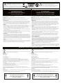 2
2
-
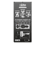 3
3
-
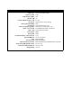 4
4
-
 5
5
-
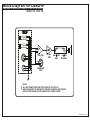 6
6
-
 7
7
-
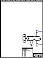 8
8
-
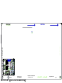 9
9
-
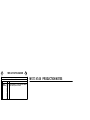 10
10
-
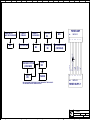 11
11
-
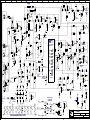 12
12
-
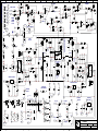 13
13
-
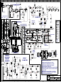 14
14
-
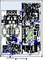 15
15
-
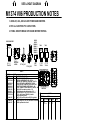 16
16
-
 17
17


YORKVILLE LS801P Manuel utilisateur
- Catégorie
- Équipement musical supplémentaire
- Taper
- Manuel utilisateur
Documents connexes
-
Yorkville Sound LS801P Manuel utilisateur
-
-
 YORKVILLE LS801P Le manuel du propriétaire
-
-
-
 YORKVILLE C1891 Manuel utilisateur
-
 YORKVILLE LS800P Manuel utilisateur
-
 YORKVILLE YBA300 Manuel utilisateur
-
 YORKVILLE EP1 Manuel utilisateur
-
 YORKVILLE C2891 Manuel utilisateur


Autres documents
-
Crest Audio LQ10P LOUDSPEAKER - S Manuel utilisateur
-
Electrolux TRIMKITEZ1 Manuel utilisateur
-
Crow CR-DU-HUM Guide d'installation
-
-
Korg 770 Manuel utilisateur
-
Rane GE 60 Schematic
-
Bang & Olufsen Beogram 5005 Manuel utilisateur
-
-
-