Johnson Controls tyco Kantech T-MUL-MT-KP Manuel utilisateur
- Taper
- Manuel utilisateur

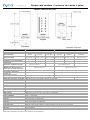
Smart card readers / Lecteurs de cartes à puce
Mullion / Meneau de porte
Technical Specifications
Mullion Single Gang
Model KT-MUL-MT-KP KT-MUL-MT KT-MUL-SC KT-SG-MT-KP KT-SG-MT KT-SG-SC
RF technologies
13.56 MHz
125 kHz
13.56 MHz
125 kHz
13.56 MHz
13.56 MHz
125 kHz
13.56 MHz
125 kHz
13.56 MHz
Power consumption (mA) @ 12
VDC Peak / AVG
200 mA / 80 mA 120 mA / 70 mA 120 mA / 70 mA 200 mA / 80 mA 120 mA / 70 mA 120 mA / 70 mA
Weight 110 g (0.24 lb) 110 g (0.24 lb) 105 g (0.23 lb) 175 g (0.4 lb) 170 g (0.37 lb) 165 g (0.36 lb)
Capacitive Touch Keypad with
backlighting
Yes No No Yes No No
Typical read range 125 kHz
ioProx ID-1 credentials (Cards)
Up to 5.1 cm (2") -- Up to 6.8 cm (2.7") --
Typical read range 13.56 MHz
MIFARE Plus EV1, encrypted
sector, ID-1 credentials (Cards)
Up to 3.8 cm (1.5") Up to 4.3 cm (1.7")
Mounting Mullion Single Gang, North America / Europe
Dimension in millimeters
(H x W x D)
115.8 x44.6 x24.7 115.8 x71.5 x24.7
Dimensions in inches
(H x W x D)
4.56 x1.75 x0.97 4.56 x2.81 x0.97
Supported credentials 125 kHz ioProx and HID® -- ioProx and HID® --
Supported credentials 13.56 MHz MIFARE Plus EV1 and ISO/IEC 14443A and14443B
Wiring terminal 6 screwless poles
Tamper Optical
Wiegand communication Formats Kantech SSF / Kantech XSF / 26-bit / 34-bit
Sounder Integrated
AES-128 security From the ioSmartcard to the reader.From the reader to the access controlunit over RS-485.
Output RS-485: 1 supervised open-drain, up to 750 mA
Operating temperature - 40°C to +70°C (- 40°F to +158°F). - 35°C to +66°C (- 31°F to +151°F) for UL listed product.
Operating humidity 0 to 95% non-condensing. 85% non-condensing for UL listed product.
LED indicator Multi-color bar: Red, green, yellow, blue, configurable
Inputs in Wiegand mode LED and buzzer
Inputs in RS-485 2 to 4, configurable
Input voltage 8.5 VDC to 16 VDC (provided by UL 294 or UL 603 listed, power limited power source).
Housing Polycarbonate, smoked black
Flammability rating UL94 V-2
Firmware Fully upgradable using RS-485
Ingress protection rating IP55 (not verified by UL).
Communication RS-485: NIST CAVP validation number AES 3667, key length 128; or Wiegand.
Cabling 3 twisted pairsAWG 22 unshielded or CAT5, up to 150 m (500')
1
Warranty Limited lifetime
Certifications FCC/IC, CE, UL294, NIST, FIPS 197, RoHS, WEEE
1
Refer to the installation manual for more details on wiring distances.

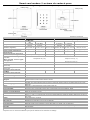
Smart card readers / Lecteurs de cartes à puce
Single Gang / Boîte électrique simple
Spécifications techniques
Meneau de porte Boîte électrique simple
Modèle
KT-MUL-MT-
KP
KT-MUL-MT KT-MUL-SC KT-SG-MT-KP KT-SG-MT KT-SG-SC
Fréquences de transmission
13,56MHz
125kHz
13,56MHz
125kHz
13,56MHz
13,56MHz
125kHz
13,56MHz
125kHz
13,56MHz
Consommation (mA) à 12Vc.c.
(pointes / moyenne)
200mA / 80 mA 120mA / 70 mA 120mA / 70 mA 200mA / 80 mA 120mA / 70 mA 120mA / 70 mA
Poids 110g (0,24lb) 110g (0,24lb) 105g (0,23lb) 175g (0,4lb) 170g (0,37lb) 165g (0,36lb)
Clavier tactile capacitif avec
rétroéclairage
Oui Non Non Oui Non Non
Distance de lecture moyenne à
25kHz ioProx, carte type ID-1
Jusqu'à 5.1cm (2") -- Jusqu'à 6.8cm (2,7") --
Distance de lecture moyenne
à13,56MHz
Mifare Plus EV1, secteur crypté,
carte type ID-1
Jusqu'à 3.8cm (1,5") Jusqu'à 4.3cm (1,7")
Compatibilité d'installation
Meneau de porte
Boîte électrique simple pour
l'Amérique du Nord / Europe
Dimension en millimètres
(H x L x P)
115,8 x44,6 x24,7 115,8 x71,5 x24,7
Dimension en pouces
(H x L x P)
4,56 x1,75 x0,97 4,56 x2,81 x0,97
Format de cartes supporté
125MHz
ioProxet HID® -- ioProxetHID® --
Format de cartes supporté
13,56MHz
MIFARE Plus EV1et ISO / IEC 14443A et14443B
Bornes de câblage 6pôles sansvis
Anti-sabotage Optique
Formats de Communication
Wiegand
Kantech SSF / Kantech XSF / 26bits / 34bits
Avertisseur sonore Intégré
Sécurité, cryptage AES-128
À partir de la carte ioSmart jusqu'au lecteur. À partir du lecteur jusqu'au contrôleurd'accès en mode
RS-485
Sortie RS-485: 1supervisée drain ouvert, jusqu'à 750 mA
Température de fonctionnement - 40°C à +70°C (- 40°F à +158°F). - 35°C à +66°C (- 31°F à +151°F) pour les produits UL listed.
Taux d'humidité 0 à 95% sanscondensation. 85% sans condensation pour les produit ULlisted.
Voyant DEL Barre multicolore: Rouge, verte, jaune, bleue et couleurs obtenuespar configuration
Entrées en mode Wiegand DEL et avertisseursonore
Entrées en mode RS-485 2 à 4, configurable
Alimentation
8,5Vc.c. à 16Vc.c. (fournie par une source d'alimentation à puissance limitée, référencée UL 294 ou
UL 603).
Boîtier Polycarbonate, noir fumé
Indice d'inflammabilité UL94 V-2
Micrologiciel Entièrement évolutifau moyendubus RS-485
Indice de protection IP55 (non vérifié par UL).
Communication RS-485: NIST CAVP validation number AES 3667, key length 128; ou Wiegand.
Câblage 3paires torsadées, 22AWG, non blindé ou CAT5, jusqu'à150m (500pi)
1
de long
Garantie Àvie limitée
Certifications FCC/IC, CE, UL294, NIST, FIPS 197, RoHSet WEEE
1
Reportez-vous au manuel d'installation pour plus de détails sur les distances de câblage.

Smart card readers / Lecteurs de cartes à puce
Mounting instructions
To install the reader, complete the following steps:
1. Pull the cable from the wall through the hole of the
mounting plate.
2. Attach the mounting plate to the wall.
3. For tamper detection, cut the plastic tab from the mount-
ing plate.
4. Fasten the white reflector tab back on the wall.
5. After installing the wiring as per the wiring charts, insert
the hook at the top of the cover into the mounting plate
tab and press the bottom of the cover until the bottom
hook snaps into place.
6. Use the provided Phillip's head screw to secure the bot-
tom of the reader.
Note: If using CAT5 cable, use two wires for GND, and two wires
for PWR.
Instructions pour montage
Pour installer le lecteur:
1. Tirez le câble du mur et le passer à travers la plaque
de montage.
2. Fixez la plaque de montage au mur.
3. Pour une détection d'anti-sabotage, coupez la languette
en plastique à partir de la plaque de montage.
4. Refixez la languette blanche du réflecteur sur le mur.
5. Après l'installation du câblage conformément aux
schémas de câblage, insérez le crochet en haut du
couvercle dans la languette de la plaque de montage
et appuyez sur le bas du couvercle jusqu'à ce que le
crochet inférieur s'enclenche.
6. Utilisez la vis à tête Phillips pour fixer la partie
inférieure du lecteur.
Note: Si vous utilisez un câble CAT5, utilisez deux fils pour GND et
deux fils pour PWR.
Take note of the
serial number,
you need it
in EntraPass /
Prenez note du
numéro de série,
car vous pourriez
en avoir besoin
dans EntraPass
3
4
FCC COMPLIANCE STATEMENT
CAUTION: Changes or modifications not expressly approved by KANTECH could void your authority to use this equipment.
This equipment generates and uses radio frequencyenergy and if not installed and used properly, in strict accordance with the manufacturer’s instructions, may cause
interference to radio and television reception. It has been type tested and found to comply with the limitsfor Class B device in accordance with the specifications in Sub-
part “B” of Part 15 of FCC Rules, which are designed to provide reasonable protection against such interference in any residential installation. However, there isno guar-
antee that interference will not occur in a particular installation. If thisequipment does cause interference to television or radio reception, which can be determined by
turning the equipment off and on, the user is encouraged to try to correct the interference by one or more of the following measures:
n Re-orient the receiving antenna.
n Relocate the alarm control with respect to the receiver.
n Move the alarm control away from the receiver.
n Connect the alarm control into a different outlet so that alarm control and receiver are on different circuits.
If necessary, the user should consult the dealer or an experienced radio/television technician for additional suggestions. The user may find the following booklet prepared
by the FCC useful: “How to Identifyand Resolve Radio/Television Interference Problems”. This booklet isavailable from the U.S. Government Printing Office, Wash-
ington D.C. 20402, Stock # 004-000-00345-4.
INDUSTRY CANADA STATEMENT
CAN-ICES-3(B)/NMB-3(B)
UL294 Performance Levels:
Destructive Attack: LevelI(no attack test)
Line Security: LevelIII via RS-485 communication and EntraPass reader template having Buzzer enabled for Comm fail alarm; Level1 via
Wiegand communication.
Endurance: LevelIV (100,000 cycles)
Standby Power: LevelI(no integralstandbypower)
Installation location and wiring methodsshallbe in accordance with the NationalElectricalCode, ANSI/NFPA 70. There isno maintenance required and there are no
replacement partsrequired for these devices.
Mullion MT Mullion SC
FCC ID: V8515KTMULMTKP FCC ID: V8515KTMULSCKP
IC: 5690B-KTMULMTKP IC: 5690B-KTMULSCKP
Single Gang MT Single Gang SC
FCC ID:V8515KTSGMTKP FCCID:V8515KTSGSCKP
IC:5690B-KTSGMTKP IC: 5690B-KTSGSCKP
Thisdevice complieswith IndustryCanada licence-exempt RSSstandard(s). Operation issubject to the following two conditions: (1) thisdevice maynot cause inter-
ference, and (2) thisdevice must accept anyinterference, including interference that may cause undesired operation of the device.
Le présent appareilest conforme auxCNR d'Industrie Canada applicablesauxappareilsradio exemptsde licence. L'exploitation est autorisée
auxdeuxconditionssuivantes: (1) l 'appareil ne doit pasproduire de brouillage, et (2) l 'utilisateurde l 'appareil doit acceptertout brouillage radioélectrique subi, même
sile brouillage est susceptible d 'en compromettre le fonctionnement.
Thisdevice complieswith Part 15 ClassBof the FCC rules. Operation issubject to the following two conditions: (1) thisdevice maynot cause harmfulinterference, and
(2) thisdevice must accept anyinterference received including interference that maycause undesired operation. ThisclassBdigitalapparatusmeetsallrequirementsof
the Canadian Interference Causing Equipment RegulationsCANICES-3 (B) / NMB-3 (B).

Smart card readers / Lecteurs de cartes à puce
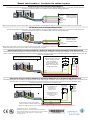
Wiegand wiring chart / Schéma de câblage Wiegand
The following diagram shows how to connect the reader to the host controller using Wiegand wiring. / Le schéma suivant démontre
comment connecter le lecteur au contrôleur hôte à l'aide du câblage Wiegand.
Data0
Data1
GND
8.5-16VDC
LED
Piezo
PWR
D1/
X+
LED/
I1
GND
D0/
X-
BUZ/
I2O
D0
D1
GND
PWR
LED
BUZ
Host controller
weigand interface /
Interface weigand
du contrôleur hôte
Note: If using CAT5 cable, use two wires for GND, and two wires for PWR. / Si vousutilisez un câble CAT5, utilisez deux fils pour GND et deux fils pour PWR.
RS-485 wiring chart / Schéma de câblage RS-485
The following diagram shows how to connect the reader to the host controller using RS-485 wiring. / Le schéma suivant démontre
comment connecter le lecteur au contrôleur hôte à l'aide du câblage Wiegand.
X+
GND
8.5-16VDC
X-
GND
D0/
X-
BUZ/
I2O
PWR
D1/
X+
LED/
I1
X-
X+
GND
PWR
Host controller
RS485 interface /
Interface RS485
du contrôleur hôte
Note: If using CAT5 cable, use two wires for GND, and two wires for PWR. / Si vous utilisez un câble CAT5, utilisez deux fils pour GND et deux fils pour PWR.
The RS-485 mode supports two accesscontrollers, the KT-400 and the KT-1 (COM2).
Optional input wiring connections RS-485 only / Schéma de câblage des entrées facultatives en RS-485 seulement
The following diagram shows how to connect the reader for optional input connections. This wiring is in addition to connecting to the host con-
troller. / Le schéma suivant démontre comment connecter le lecteur pour les connexions d'entrées facultatives. Ce câblage s'ajoute à la con-
nexion au contrôleur hôte.
Alarm /
Alarme
Input 1 Input 2
5.6K
5.6K
5.6K
Only use copper conductors /
Utilisez uniquement des conducteurs en cuivre
GND
D0/
X-
BUZ/
I2O
PWR
D1/
X+
LED/
I1
Zone termination: NC, NO,
NEOL, single or double
EOL termination. /
Zone de terminaison:
terminaison NC, NO,
NEOL, EOL simple ou
double terminaison.
GND
I1
GND
I2O
Tamper /
Anti-sabotage
Optional lock wiring connections RS-485 only / Schéma de câblage du verrou facultatif en RS-485 seulement
The following diagram shows how to connect the reader for an optional lock connection. This connection is in addition to the connection to the
host controller. / Le schéma suivant démontre comment connecter le lecteur pour la connexion du vérou facultatif. Cette
connexion s'ajoute à la connexion au contrôleur hôte.
External power supply / Alimentation
électrique externe 12VDC 750mA max.
I1 programmed as
dual input /
I1
programée en
double entrée
I2O programmed as
lock output / I2O
programé en sortie
de gâche
REX
5.6K
11.1K
Door contact
/ contact porte
Door
locking
device /
Dispositif
de
fermeture
de porte
GND
D0/
X-
BUZ/
I2O
PWR
D1/
X+
LED /
I1
GND
I1
I2O
GND
12VDC
Only use copper conductors /
Utilisez uniquement des conducteurs en cuivre
Note: Use 5.6K for Input 1 and 11.1K for Input 2 / Utilisez du 5.6K pour l'entrée 1et 11.1K pur l'entrée 2
© 2019 Johnson Controls. All rights reserved.
JOHNSONCONTROLS, TYCO and KANTECH are trademarks
and/or registered trademarks. Unauthorized use is strictly prohibited.
Toll Free: 1-888-222-1560. Telephone: 1 (450) 444-2030.
www.kantech.com
-
 1
1
-
 2
2
-
 3
3
-
 4
4


Johnson Controls tyco Kantech T-MUL-MT-KP Manuel utilisateur
- Taper
- Manuel utilisateur
dans d''autres langues
Autres documents
-
Yes T36FT810NS Le manuel du propriétaire
-
Yes B30IR900SP Wi Fi Module Statements
-
Verkada AD31 Mode d'emploi
-
 Kantech Access Control and Accessories USB-485 Manuel utilisateur
-
PRASTEL MEDIPROMF Manuel utilisateur
-
-
 Farpointe Data CSR-35 Mode d'emploi
-
Farpointe Data CONEKT5 Mode d'emploi
-
 Retekess T-AC04 Metal Standalone Keypad Access Control Manuel utilisateur
-
Allmatic TP1 Guide de démarrage rapide


