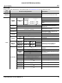
Iluminarc LOGIC Wall Panel Guide de référence
- Catégorie
- Projecteurs
- Taper
- Guide de référence

English EN
Español ES
Français FR
Deutsch DE
Nederlands NL
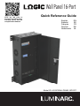
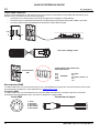
Quick Reference Guide
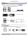
Model ID: LOGICWALLPANEL16PORT
Scan the QR code to
access the product page,
warranty terms, and the
complete User Manual
Wall Panel 16-Port

1
EN
QUICK REFERENCE GUIDE
LΩGIC Wall Panel 16- Port QRG Rev. 2
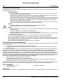
Safety Notes
These Safety Notes include important information about installation, use, and maintenance of the LΩGIC Wall Panel 16-
Port.
FCC Statement of Compliance
This device complies with Part 15 Part B of the FCC rules. Operation is subject to the following two conditions:
1. This device may not cause harmful interference, and
2. This device must accept any interference received, including interference that may cause undesired operation.
This equipment has been tested and found to comply with the limits for a Class B digital device, pursuant to Part 15 of the
FCC Rules. These limits are designed to provide reasonable protection against harmful interference in a residential
installation. This equipment generates uses and can radiate radio frequency energy and, if not installed and used in
accordance with the instructions, may cause harmful interference to radio communications. However, there is no
guarantee that interference will not occur in a particular installation. If this equipment does cause harmful interference to
radio or television reception, which can be determined by turning the equipment off and on, the user is encouraged to try
to correct the interference by one or more of the following measures:
• Reorient or relocate the receiving antenna.
• Increase the separation between the equipment and receiver.
• Connect the equipment into an outlet on a circuit different from that to which the receiver is connected.
• Consult the dealer or an experienced radio/TV technician for help.
Any changes or modifications not expressly approved by the party responsible for compliance could void the user’s
authority to operate the equipment.
What is Included
AC Power
This product has an auto-ranging power supply that can work with an input voltage range of 200–240 VAC, 50/60 Hz.
AC Plug
• CAUTION:
• This product’s housing may be hot when operating. Mount this product in a location with adequate
ventilation, at least 20 in (50 cm) from adjacent surfaces.
• When transferring the product from extreme temperature environments, (e.g., cold truck to warm humid
ballroom) condensation may form on the internal electronics of the product. To avoid causing a failure,
allow the product to fully acclimate to the surrounding environment before connecting it to power.
• Only qualified and competent persons should open this product for servicing. Turn off power before
servicing!
• An external breaker and/or fuse branch-type overcurrent protection is required when running the product
under a municipal electric environment.
• ALWAYS:
• Use a safety cable when mounting this product overhead.
• Connect this product to a grounded and protected circuit.
•DO NOT:
• Leave any flammable material within 0.3 m of this product while operating or connected to power.
• Connect this product to a dimmer or rheostat.
• Operate this product if the housing or cables appear damaged.
• Operate this product outdoors or in any location where dust, excessive heat, water, or humidity may affect
it. (IP20)
• The maximum ambient temperature is 113 °F (45 °C). Do not operate this product at higher temperatures.
• The minimum ambient temperature is -4°F (-20°C). Do not operate the product at lower temperatures.
• To eliminate unnecessary wear and improve its lifespan, during periods of non-use completely disconnect the
product from power via breaker or by unplugging it.
• In the event of a serious operating problem, stop using immediately.
•LΩGIC Wall Panel 16- Port
• Door keys (X2)
• Quick Reference Guide
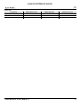
Connection Wire (U.S.) Wire (Europe) Screw Color
AC Live Black Brown Yellow/Brass
AC Neutral White Blue Silver
AC Ground Green/Yellow Green/Yellow Green

EN
2
LΩGIC Wall Panel 16- Port QRG Rev. 2
QUICK REFERENCE GUIDE
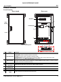
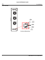
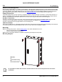
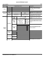
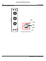
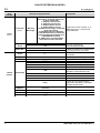
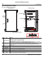
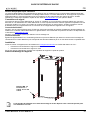
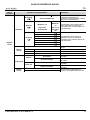
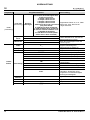
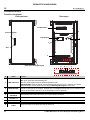
Product Overview
Front Overview
#Name Function
1 LED indicators
POWER: green, indicates power connection
ETHERNET: yellow, indicates ethernet connection
ACTIVITY (control): white, indicates controller signal
ERROR/ALERT: disconnected fixtures cause this LED to light, among other alerts. Red,
indicates an error (see Warning Messages in the menu)
2
MENU/ENTER
Rotate to navigate upwards or downwards through the menu list, and increase or decrease a
selected numeric value. Push to enable the currently displayed menu option or set the currently
selected value into the selected function.
3 <BACK> button Exits the current menu or function
4LOGIC FIXTURE
OUTPUTS IEEE 802.3bt POE RJ45 connector for output LΩGIC products
5
WALL CON
OUTPUT 1/2
RJ12 connectors for LΩGIC Wall Controller
6 DMX IN 5-pin phoenix connector for DMX input
7 DMX THRU 5-pin phoenix connector for DMX output
8NETWORK IN/
THRU RJ45 connectors for Ethernet input and through
Door
handle
LCD Display
Breakers
Door closed Door open
3
2
Lock
1
4
5678
Rack/ mounting ears

3
EN
QUICK REFERENCE GUIDE
LΩGIC Wall Panel 16- Port QRG Rev. 2
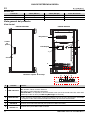
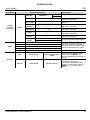
Side Overview
2 in
51 mm
1.75 in
44 mm
1.5 in
38 mm
1.25 in
32 mm
knockout dimensions
1 in
25 mm

EN
4
LΩGIC Wall Panel 16- Port QRG Rev. 2
QUICK REFERENCE GUIDE
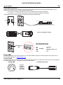
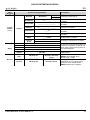
LΩGIC Wall Controller
Each LΩGIC Wall Panel 16- Port comes with a wall-mounted control panel (LΩGIC Wall Controller) which can plug into
the RJ12 connector on the back of the product. Download the User Manual from www.iluminarc.com for more
information.
• Buttons 1–8 trigger playback of the corresponding recorded programs.
• Buttons 9 and 10 decrease and increase the brightness of the connected LOGIC products.
• 5-bit DIP switches set the address of the LΩGIC Wall Controller.
DMX Linking
The LΩGIC Wall Panel 16- Port will work with a DMX controller using a 5-pin phoenix connector. A DMX Primer is
available from www.iluminarc.com.
DMX Connection
The LΩGIC Wall Panel 16- Port provides a DMX 512 connection using a 5-pin phoenix connector. See the User Manual
for information about connecting and configuring the product for DMX operation.
1–8
910
RJ12 with flipped/ reverse wiring
DIP switches use binary addressing
DIP switches
5=1
4=2
3=4
2=8
1=16
Example:
5-1 (ON)
4-0
3-1 (ON) = 00101 = 5
2-0
1-0
1. Ground
2. Data 1 -
3. Data 1 +
4. Not used
5. Not used
DMX Output Signal Connector

5
EN
QUICK REFERENCE GUIDE
LΩGIC Wall Panel 16- Port QRG Rev. 2
Remote Device Management
Remote Device Management, or RDM, is a standard for allowing DMX-enabled devices to communicate bi-directionally
along existing DMX cabling. Check the DMX controller’s User Manual or with the manufacturer as not all DMX controllers
have this capability. The LΩGIC Wall Panel 16- Port supports RDM protocol that allows feedback to make changes to
menu map options. Download the User Manual from www.iluminarc.com for more details and an RDM chart.
Signal Connection
The LΩGIC Wall Panel 16- Port can link to controller software using an Ethernet connection. If using other Art-Net™ or
sACN -compatible products with the LΩGIC Wall Panel 16- Port, you can control each individually on a single network.
See the User Manual for information about how to connect and configure the product for these signals.
Art-Net™ Connection
Art-Net™ is an Ethernet protocol that uses TCP/IP which transfers a large amount of DMX512 data using an RJ45
connection over a large network. An Art-Net™ protocol document is available from www.iluminarc.com.
Art-Net™ designed by and copyright Artistic Licence Holdings Ltd.
sACN Connection
Also known as ANSI E1.31, Streaming-ACN is an Ethernet protocol that uses the layering and formatting of Architecture
for Control Networks to transport DMX512 data over IP or any other ACN compatible network.
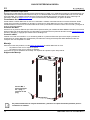
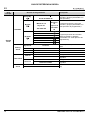
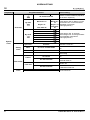
Mounting
Before mounting this product, read the Safety Notes. The LΩGIC Wall Panel 16- Port:
• Can be mounted using a wall mount.
• can be mounted using a rack mount.
Make sure the mounting hardware is capable of supporting the weight of the product.
Mounting Diagram
It is possible to detach the rack ears and move them to the front of the product for rack mount
installation.
M8 bolts,
or
1/4 In bolts/screws,
or
3/8 in bolt/screws

EN
6
LΩGIC Wall Panel 16- Port QRG Rev. 2
QUICK REFERENCE GUIDE
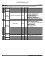
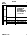
Menu Map
Refer to the LΩGIC Wall Panel 16- Port product page on www.iluminarc.com for the latest menu map.
Main Level Programming Levels Description
Protocol
DMX512
Selects the control protocolArtNet
sACN
Local
Output
Status Output 1-32
Status
Status: _ _ _ _ _ Shows Normal or Fault
Connect: _ _ _ Shows On or Off
CLASS: _ _ _ _ Shows None or 1–8
V1: _._ V Cur 1: _._ mA Shows voltage and current of output
V2: _._ V Cur 2: _._ mA
Power: _._ W Shows power of output
Net Switch 2.X.X.X Selects the first value of the IP
address
10.X.X.X
Universe 000–255 / 001–256
Selects universe
(Art-Net™) (sACN)
Password ON Enables/disables password lock:
123456
OFF
Priority Control panel Wall Con input has priority
Signal Signal input has priority
History
List _ _ _ _ _ Displays connected product history
Clear No Cancel clear
Yes Clear history
Wall Con
Zone
Wall Con
Zone One Group 1-16 Wall Con
1-4
0–31
Sets zone and group of selected Wall
Con, or disables it
OFF
Wall Con
Zone Two Group 1-16 Wall Con
1-4
0–31
OFF
Local Info
Version V _._ _ Shows current firmware version
IP Address _ _ _._ _ _._ _ _._ _ _ Shows the IP address
Fixture
Hours
_ hours Shows length of time product has
been on
_ _minutes
_ _ seconds
Label LOGIC Wall Panel Shows device label
Device UID _ _ _ _ _ _-_ _ _ _ _ _ _ _ Shows device UID
MAC Address
_ _ _ _ _ _ _ _ _ _ _ _ _ _ Shows the MAC address
Temperature _ _._ °C Shows the current temperature in °C
Power 1
Temperature _ _._ °C Shows NTC 1 temperature in °C
Power 2
Temperature _ _._ °C Shows NTC 2 temperature in °C
Power 3
Temperature _ _._ °C Shows NTC 3 temperature in °C
Power 4
Temperature _ _._ °C Shows NTC 4 temperature in °C

7
EN
QUICK REFERENCE GUIDE
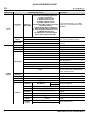
LΩGIC Wall Panel 16- Port QRG Rev. 2
Local
(cont.)
Local Info
(cont.) Warning
Messages
0. 1=DMX signal lost; 2=Network
disconnect; 3= Artnet signal lost;
4= Sacn signal lost;
1. Output 1 Overcurrent
2. Output 2 Overcurrent
3. Output 1-Short Circuit
4. Output 2-Short Circuit
5. POE Device No longer connected
(may have failed)
6. POE Device Error-undefined
7. POE Hardware Error-undefined
8. Internal network hardware error
9. DRIVER 2X Overheat
10. POE Device overheat (detail
which device when selected)
Shows current error(s), e.g. “DMX
Signal Lost” or “Devices No Longer
Detected”
System
Reset
No Resets the LΩGIC Wall Panel 16-
Port to factory default settings
Yes
Match Net No Sets fixture segment to driver
segment
Yes
Linked
Fixture
Order 1- _ Displays order of connected fixtures
Output 1-32 Displays fixture port
Model _ _ _ _ _ Displays fixture name
Personality
RED 1-channel: dimmer (red only)
GREEN 1-channel: dimmer (green only)
BLUE 1-channel: dimmer (blue only)
WHITE 1-channel: dimmer
TW 2-channel, Tunable White: dimmer,
color temperature
RGB 3-channel: RGB
RGBW 4-channel: RGBW
RGBW+D 5-channel: dimmer, RGBW
FULL 10-channel: dimmer, RGBW, color
macros, strobe, auto programs and
speed, dimmer speed
DMX
Address 001–512 Sets DMX address
Universe 0–255 Sets universe
Version v_._ _ Displays current version
Discover _ _ _ Search for device
Fixture
Network Net Switch
2. _ . _ . _
Sets the IP address
10 . _ . _ . _
IP Address 2 . _ . _ . _ Shows the linked device IP address
Device UID _ _ _ _ _ _ _ _ _ _ _ _ _ _ Shows the linked device UID
MAC
Address 0 _ _ _ _ _ _ _ _ _ _ _ _ _ _ Shows the linked device MAC
address
Temperature _ . _°C Displays linked device temperature
Label _ _ _ Displays linked device name
Fixture
Hours _ _ _ hours Displays working hours of linked
device
Factory
Reset
No Resets linked device
Yes
Main Level Programming Levels Description

EN
8
LΩGIC Wall Panel 16- Port QRG Rev. 2
QUICK REFERENCE GUIDE
Static
Red 000–255 Temporary manual control of all
connected products. Combine red,
green, blue, and white to make a
custom color.
Green 000–255
Blue 000–255
White 000–255
Strobe 000–255 Sets standalone strobe speed
Record
Play Record1–64
_ _: _ _: _ _ Record 1–64: Play/
pause
Plays back recorded input. Press the
<Encoder> knob to toggle play and
stop.
Record Record1–64 Record 1–64 Clr Captures/records live controller input
to selected Record slot. Press the
<Encoder> knob to start and stop.
System
Clock
Schedule
Everyday Turn on Turn off Schedules daily times to turn on and
off (stackable with other schedule
options)
00–23:00–59:00–59
By date
Turn on Turn off
Schedules a date and time to turn on
and off (stackable with other schedule
options)
Month:01–12 Month:01–
12
Day:01–31 Day:01–31
Year:2000–99 Year:2000–
99
By week
Mon :
Schedules which days of the week to
be on or off (stackable with other
schedule options)
Tues :
Wed :
Thur :
Fri :
Sat :
Sun :
Setting
Clock
SysClock: 24 hours Shows system clock is 24-hour
Date: 01–12:01–31:2000–2099 Sets the current date
Time: 00–23:00–59:00–59 Sets the current time
Week: 1–7 Sets the current day of the week
Fade In/Out
Fade In On-instant Sets fade in to instant
On-3second fade Sets fade in to 3-second fade
Fade Out Off-instant Sets fade out to instant
Off-3second fade Sets fade out to 3-second fade
Enable
Clock
No Enables/disables clock functions
Yes
Main Level Programming Levels Description

9
EN
QUICK REFERENCE GUIDE
LΩGIC Wall Panel 16- Port QRG Rev. 2
RDM Chart
Refer to the LΩGIC Wall Panel 16- Port product page on www.iluminarc.com for the latest RDM Chart.
GET SET
Category RDM Parameter IDs (Slot 21-22) Value
Required
Detail
Network
Management
DISC_UNIQUE_BRANCH 0x0001
DISC_MUTE 0x0002
DISC_UN_MUTE 0x0003
RDM
Information
QUEUED_MESSAGE 0x0020
SUPPORTED_PARAMETERS 0x0050
IDENTIFY_DEVICE, DEVICE_INFO,
SOFTWARE_VERSION_LABEL,
SUPPORTED_PARAMETERS,
DMX_START_ADDRESS,
DEVICE_MODEL_DESCRIPTION,
MANUFACTURER_LABEL,
DEVICE_LABEL, DMX_PERSONALITY,
PERSONALITY_DESCRIPTION,
SENSOR_DEFINITION, SENSOR_VALUE
PARAMETER_DESCRIPTION 0x0051
Product
Information
DEVICE_INFO 0x0060
1, RDM Protocol Version: V1.0;
2, Device_Mode_ID: 0x21A408B9;
3, Product Category Defines:
PRODUCT_CATEGORY_FIXTURE_FIXED;
4, Software Version ID;
5, DMX512 Footprint;
6, DMX512 Personality;
7, DMX512 Start Address;
8, Sensor Count;
PRODUCT_DETAIL_ID_LIST 0x0070
DEVICE_MODEL_DESCRIPTION 0x0080 LOGIC WALL PANEL
MANUFACTURER_LABEL 0x0081 ILUMINARC
DEVICE_LABEL 0x0082 LOGIC WALL PANEL
SOFTWARE_VERSION_LABEL 0x00C0 V_._
FACTORY_DEFAULTS FACTORY_DEFAULTS : yes
DMX Setup
DMX_PERSONALITY 0x00E0 9pcs persons
DMX_PERSONALITY_DESCRIPTION
0x00E1 RED/1CH, GREEN/1CH, BLUE/1CH,
WHITE/1CH, TW/2CH, RGB/3CH, RGBW/
4CH, RGBW+D/5CH, FULL/10CH
DMX_START_ADDRESS 0x00F0 1-503
Sensors SENSOR_DEFINITION 0x0200 0.) Product Temperature _ _ °C
SENSOR_VALUE 0x0201 —20° —100°
Control IDENTIFY_DEVICE 0x1000 Identify State: Off

ES
10
LOGIC Wall Panel 16- Port GRR Rev. 2
GUÍA DE REFERENCIA RÁPIDA
Notas de seguridad
Estas notas de seguridad incluyen información importante sobre la instalación, el uso y el mantenimiento del
LOGIC Wall Panel 16- Port.
Declaración de conformidad de la FCC
Este dispositivo cumple con la Parte 15 Parte B de las normas de la FCC. El funcionamiento está sujeto a las dos
condiciones siguientes:
1. Este dispositivo no puede causar interferencias perjudiciales, y
2. Este dispositivo debe aceptar cualquier interferencia recibida, incluyendo las que puedan causar un
funcionamiento no deseado.
Este equipo ha sido probado y cumple los límites establecidos para los dispositivos digitales de Clase B, de conformidad
con la Parte 15 de las normas de la FCC. Estos límites están diseñados para proporcionar una protección razonable
contra las interferencias perjudiciales en una instalación residencial. Este equipo genera, utiliza y puede irradiar energía
de radiofrecuencia y, si no se instala y utiliza de acuerdo con las instrucciones, puede causar interferencias perjudiciales
en las comunicaciones por radio. Sin embargo, no hay garantía de que no se produzcan interferencias en una instalación
concreta. Si este equipo causa interferencias perjudiciales en la recepción de radio o televisión, lo cual puede
determinarse apagando y encendiendo el equipo, se recomienda al usuario que intente corregir las interferencias
mediante una o varias de las siguientes medidas:
• Reorientar o reubicar la antena receptora.
• Aumentar la separación entre el equipo y el receptor.
• Conectar el equipo a una toma de corriente de un circuito distinto al que está conectado el receptor.
• Consulte al distribuidor o a un técnico experto en radio/TV para obtener ayuda.
Cualquier cambio o modificación que no esté expresamente aprobado por la parte responsable del cumplimiento podría
anular la autoridad del usuario para operar el equipo.
Qué se incluye
Corriente Alterna
Este producto tiene una fuente de alimentación con detección automática que.uede funcionar con un rango de tensión
de entrada de 200 a 240 VCA, 50/60 Hz.
• PRECAUCIÓN:
• Solo personal calificado y competente debe abrir este producto para su mantenimiento.
¡Desconecte la
alimentación antes de realizar el mantenimiento!
•
La carcasa de este producto puede estar caliente durante su funcionamiento. Monte este producto en un lugar
con una ventilación adecuada, a una distancia mínima de 50 cm (20 pulg.) de las superficies adyacentes.
• Cuando se transfiere el producto desde entornos con temperaturas extremas (por ejemplo, de un camión
refrigerado a un salón de baile cálido y húmedo), puede formarse condensación en los componentes
electrónicos internos del producto. Para evitar que se produzca una falla, deje que el producto se aclimate
completamente al entorno antes de conectarlo a la corriente.
•Se requiere una protección contra sobrecorriente de tipo ramal mediante disyuntor externo y/o fusible
cuando el producto funciona en un entorno eléctrico municipal.
•SIEMPRE:
• Utilice un cable de seguridad cuando monte este producto por encima de la cabeza.
• Conecte este producto a un circuito con toma de tierra y protegido.
• NO HACER:
• Dejar cualquier material inflamable a menos de 0.3 m de este producto mientras esté en funcionamiento
o conectado a la corriente.
• Conectar este producto a un regulador o reostato.
• Utilizar este producto si la carcasa o los cables parecen estar dañados.
• Utilizar este producto al aire libre o en cualquier lugar donde el polvo, el calor excesivo, el agua o la
humedad puedan afectarlo. (IP20)
• La temperatura ambiente máxima es de 45 °C (113 °F). No utilice este producto a temperaturas más altas.
• La temperatura de ambiente mínima es de -20 °C (-4 °F). No utilice este producto a temperaturas más bajas.
• Para eliminar el desgaste innecesario y mejorar su vida útil, durante los periodos en que no lo utilice,
desconecte completamente el producto de la corriente mediante un disyuntor o desenchufándolo.
• En caso de un problema grave de funcionamiento, deje de usarlo inmediatamente.
• LOGIC Wall Panel 16- Port
• Llaves de puetra (X2)
• Guía de Referencia Rápida

11
ES
GUÍA DE REFERENCIA RÁPIDA
LOGIC Wall Panel 16- Port GRR Rev. 2
Enchufe CA
Vista general del producto
Vista frontal
Conexión Cable (EE.UU.) Cable (Europa) Color del tornillo
CA Cargado Negro Marrón Amarillo/Latón
CA Neutro Blanco Azul Plata
CA Tierra Verde/Amarillo Verde/Amarillo Verde
#Nombre Función
1 LED indicators
POWER: verde, indica conexión de alimentación
NET: amarillo, indica conexión Ethernet
ACT: blanco, indica señal del controlador
ERROR/ALERT: Los dispositivos desconectados hacen que se encienda este LED, entre otras
alertas.rojo, indica un error (ver Warning Messages en el menú)
2
MENU/ENTER
Gire para desplazarse hacia adelante o hacia atrás por la lista de menú, y aumente o disminuya
un valor numérico seleccionado. Pulse para habilitar la opción de menú actualmente visualizada
o configurar el valor seleccionado actualmente dentro de la función seleccionada.
3 <BACK> button Sale del menú o función actual
4LOGIC FIXTURE
OUTPUTS Conector RJ45 POE IEEE 802.3bt para productos LΩGIC de salida.
5
WALL CON
OUTPUT 1/2
Conector RJ12 para LΩGIC Wall Controller
Tirador
de
puerta
LCD Display
Disyuntores
Puerta cerrada Puerta abierta
3
2
Cerradura
1
4
5678
Bastidor/ orejetas de montaje

ES
12
LOGIC Wall Panel 16- Port GRR Rev. 2
GUÍA DE REFERENCIA RÁPIDA
6 DMX IN Conector Phoenix de 5 pines para entrada DMX
7 DMX THRU Conector Phoenix de 5 pines para salida DMX
8NETWORK IN/
THRU Conectores RJ45 para entrada y paso de Ethernet
#Nombre Función

13
ES
GUÍA DE REFERENCIA RÁPIDA
LOGIC Wall Panel 16- Port GRR Rev. 2
Descripción general lateral
2’’
51 mm
1.75‘’
44 mm
1.5’’
38 mm
1.25’’
32 mm
Dimensiones de perforación
1’’
25 mm

ES
14
LOGIC Wall Panel 16- Port GRR Rev. 2
GUÍA DE REFERENCIA RÁPIDA
LΩGIC Wall Controller
Cada LOGIC Wall Panel 16- Port viene con un panel de control de montaje mural (LΩGIC Wall Controller) que se
conecta a un conector RJ12 en la parte posterior del producto.
• Los botones 1-8 activan la reproducción de los correspondientes programas grabados.
• Los botones 9 y 10 aumentan o disminuyen el brillo de los productos LΩGIC conectados.
Conmutadores DIP de 5 bits configuran la dirección del LΩGIC Wall Controller
Enlace DMX
El LOGIC Wall Panel 16- Port funcionará con un controlador DMX usando una conector phoenix de 5 pines. Hay un
Manual DMX disponible en www.iluminarc.com.
Conexión DMX
El LOGIC Wall Panel 16- Port dispone de conexión DMX 512 mediante un conector Phoenix de 5 pines. Vea el Manual
de usuario para conectar y configurar para funcionamiento DMX.
1–8
910
RJ12 con cableado cruzado
Interruptores DIP utilizan
direccionamiento binario
Interruptores
DIP 5=1
4=2
3=4
2=8
1=16
Ejemplo:
5-1 (ON)
4-0
3-1 (ON) = 00101 = 5
2-0
1-0
1. Tierra
2. Datos -
3. Datos +
4. Sin uso
5. Sin uso
Salida DMX Conector de señal

15
ES
GUÍA DE REFERENCIA RÁPIDA
LOGIC Wall Panel 16- Port GRR Rev. 2
gestión remota del dispositivo
Remote Device Management (gestión remota del dispositivo) o RDM, es un estándar que permite a los dispositivos con
capacidad DMX una comunicación bidireccional por un cableado DMX existente. El LOGIC Wall Panel 16- Port admite
protocolo RDM, que posibilita información para supervisar cambiar las opciones del mapa de menú. Descargue el
manual de usuario de www.iluminarc.com para una información más detallada y un gráfico de RDM.
Conexiones de señal
Puede enlazar el LOGIC Wall Panel 16- Port a un controlador o software controlador usando una conexión Ethernet. Si está
usando otros
productos compatibles con Art-Net™ o sACN con el LOGIC Wall Panel 16- Port, puede controlar cada uno
individualmente en una sola
red. Consulte el Manual de usuario para obtener información sobre cómo conectar y configurar el
producto para estas señales.
Conexión Art-Net™
Art-Net™ es un protocolo Ethernet que utiliza TCP/IP para transferir gran cantidad de datos DMX512 usando una conexión
ethernet sobre una red de gran tamaño. Hay disponible un documento sobre el protocolo Art-Net™ desde www.iluminarc.com.
Art-Net™ diseñado y copyright por Artistic Licence Holdings Ltd.
Conexión sACN
También conocido como ANSI E1.31, el streaming ACN es un protocolo Ethernet que usa las capas y formato de
Architecture for Control Networks (arquitectura para redes de control) para transportar datos DMX512 sobre IP o
cualquier otra red compatible con ACN.
Montaje
Antes de montar este producto, lea las Notas de seguridad. El
LOGIC Wall Panel 16- Port:
• Se puede montar con un soporte de pared.
• Se puede montar con un soporte de bastidor.
Asegúrese de que los hardware de montaje son capaces de soportar el peso del producto.
Diagrama de Montaje
Es posible desmontar las orejetas de bastidor y moverlas a la parte frontal del producto para su
instalación en bastidor.
Pernos M8, o
pernos/tornillos
de ¼ pulg., o
tornillos de 3/8
pulg.

ES
16
LOGIC Wall Panel 16- Port GRR Rev. 2
GUÍA DE REFERENCIA RÁPIDA
Menu Map
Refer to the LOGIC Wall Panel 16- Port product page on www.iluminarc.com for the latest menu map.
Nivel
Principal
Niveles de Programación Descripción
Protocol
DMX512
Selecciona el protocolo de controlArtNet
sACN
Local
Output
Status Output 1-32
Status
Status: _ _ _ _ _ Muestra Normal o Fault
Connect: _ _ _ Muestra On o Off
CLASS: _ _ _ _ Muestra None o 1–8
V1: _._ V Cur 1: _._ mA Muestra la tensión y corriente de
salida
V2: _._ V Cur 2: _._ mA
Power: _._ W Muestra la potencia de salida
Net Switch 2.X.X.X Selecciona el primer valor de la
dirección IP
10.X.X.X
Universe 000–255 / 001–256 Selecciona el universo
(Art-Net™) (sACN)
Password ON Habilita/deshabilita el bloqueo de
contraseña: 123456
OFF
Priority Control panel El entrada da Wall Con tiene prioridad
Signal La entrada de señal tiene prioridad
History
List _ _ _ _ _
Muestra el historial de productos
conectados
Clear No Cancelar borrado
Yes Borrar historial
Wall Con
Zone
Wall Con
Zone One Group 1-16 Wall Con
1-4
0–31
Establece la zona de Wall Con
seleccionada o la desactiva
OFF
Wall Con
Zone Two Group 1-16 Wall Con
1-4
0–31
OFF
Local Info
Version V _._ _ Muestra instalada la versión de
firmware
IP Address _ _ _._ _ _._ _ _._ _ _ Muestra la dirección IP
Fixture
Hours
_ hours Muestra el nombre total de las horas
del producto
_ _minutes
_ _ seconds
Label LOGIC Wall Panel Muestra la etiqueta del producto
Device UID _ _ _ _ _ _-_ _ _ _ _ _ _ _ Muestra la UID del producto
MAC Address
_ _ _ _ _ _ _ _ _ _ _ _ _ _ Muestra la dirección MAC
Temperature _ _._ °C Muestra la temperatura actual en °C
Power 1
Temperature _ _._ °C Muestra la temperatura de NTC 1 en
°C
Power 2
Temperature _ _._ °C Muestra la temperatura de NTC 2 en
°C
Power 3
Temperature _ _._ °C Muestra la temperatura de NTC 3 en
°C
Power 4
Temperature _ _._ °C Muestra la temperatura de NTC 4 en
°C

17
ES
GUÍA DE REFERENCIA RÁPIDA
LOGIC Wall Panel 16- Port GRR Rev. 2
Local
(cont.)
Local Info
(cont.) Warning
Messages
0. 1=DMX signal lost; 2=Network
disconnect; 3= Artnet signal lost;
4= Sacn signal lost;
1. Output 1 Overcurrent
2. Output 2 Overcurrent
3. Output 1-Short Circuit
4. Output 2-Short Circuit
5. POE Device No longer connected
(may have failed)
6. POE Device Error-undefined
7. POE Hardware Error-undefined
8. Internal network hardware error
9. DRIVER 2X Overheat
10. POE Device overheat (detail
which device when selected)
Muestra los errores actuales, p. ej.,
“DMX
Signal Lost” o “Devices No
Longer Detected”
System
Reset
No Restablece el LOGIC Wall Panel 16-
Port a la configuración
predeterminada de fábric
Yes
Match Net No Establece el segmento de dispositivo
como segmento de controlador
Yes
Linked
Fixture
Order 1- _ Muestra el orden de los dispositivos
conectados
Output 1-32 Muestra el puerto del dispositivo
Model _ _ _ _ _ Muestra el nombre del dispositivo
Personality
RED 1 canal: atenuador (solamente rojo)
GREEN 1 canal: atenuador (solamente verde)
BLUE 1 canal: atenuador (solamente azul)
WHITE 1 canal: atenuador
TW 2 canales, Blanca Ajustable:
atenuador, temperatura de color
RGB 3 canales: control RGB
RGBW 4 canales: control RGBW
RGBW+D 5 canales: atenuador, control RGBW
FULL
10 canales: atenuador, RGBW,
macros de
color, estroboscopio,
programas automáticos
y velocidad,
velocidad de atenuador
DMX
Address 001–512 Establece la dirección DMX
Universe 0–255 Establece el universo
Version v_._ _ Muestra la versión actual
Discover _ _ _ Búsqueda de dispositivo
Nivel
Principal
Niveles de Programación Descripción

ES
18
LOGIC Wall Panel 16- Port GRR Rev. 2
GUÍA DE REFERENCIA RÁPIDA
Linked
Fixture
(cont.) Fixture
Network Net Switch
2. _ . _ . _
Establece la dirección IP
10 . _ . _ . _
IP Address 2 . _ . _ . _ Muestra la dirección IP del dispositivo
vinculado
Device UID _ _ _ _ _ _ _ _ _ _ _ _ _ _ Muestra la UID del dispositivo
vinculado
MAC
Address 0 _ _ _ _ _ _ _ _ _ _ _ _ _ _ Muestra la dirección MAC del
dispositivo vinculado
Temperature _ . _°C Muestra la temperatura del dispositivo
vinculado
Label _ _ _ Muestra el nombre del dispositivo
vinculado
Fixture
Hours _ _ _ hours Muestra las horas de funcionamiento
del dispositivo vinculado
Factory
Reset
No Restablece el dispositivo vinculado
Yes
Static
Red 000–255 Control manual temporal de todos los
productos conectados. Combina rojo,
verde, azul y blanco para generar un
color personalizado
Green 000–255
Blue 000–255
White 000–255
Strobe 000–255 Establece la frecuencia del
estroboscopio
Record
Play Record1–64
_ _: _ _: _ _ Record 1–64: Play/
pause
Reproduce la entrada grabada. Pulse
<MENU>
para cambiar entre
reproducción y pausa.
Record Record1–64 Record 1–64 Clr
Captura/graba la entrada de
controlador en vivo a la ranura de
Grabación seleccionada Pulse
<MENU> para iniciar y detener.
Nivel
Principal
Niveles de Programación Descripción

19
ES
GUÍA DE REFERENCIA RÁPIDA
LOGIC Wall Panel 16- Port GRR Rev. 2
System
Clock
Schedule
Everyday Turn on Turn off Programa las horas diarias para
encender y apagar (acumulable con
otras opciones)
00–23:00–59:00–59
By date
Turn on Turn off
Programa una fecha y hora para
encender y apagar (acumulable con
otras opciones de programación)
Month:01–12 Month:01–
12
Day:01–31 Day:01–31
Year:2000–99 Year:2000–
99
By week
Mon :
Programa qué días de la semana
estará encendido o apagado
(acumulable con otras opciones de
programación)
Tues :
Wed :
Thur :
Fri :
Sat :
Sun :
Setting
Clock
SysClock: 24 hours
Muestra que el reloj del sistema es de 24
horas
Date: 01–12:01–31:2000–2099 Establece la fecha actual
Time: 00–23:00–59:00–59 Establece la hora actual
Week: 1–7 Establece el día actual de la semana
Fade In/Out
Fade In
On-instant Configura el fade in en instantáneo
On-3second fade Configura el fade in en un fade de 3
segundos
Fade Out
Off-instant Configura el fade out en instantáneo
Off-3second fade Configura el fade out en un fade de 3
segundos
Enable
Clock
No Habilita/deshabilita las funciones del
reloj
Yes
Nivel
Principal
Niveles de Programación Descripción
La page est en cours de chargement...
La page est en cours de chargement...
La page est en cours de chargement...
La page est en cours de chargement...
La page est en cours de chargement...
La page est en cours de chargement...
La page est en cours de chargement...
La page est en cours de chargement...
La page est en cours de chargement...
La page est en cours de chargement...
La page est en cours de chargement...
La page est en cours de chargement...
La page est en cours de chargement...
La page est en cours de chargement...
La page est en cours de chargement...
La page est en cours de chargement...
La page est en cours de chargement...
La page est en cours de chargement...
La page est en cours de chargement...
La page est en cours de chargement...
La page est en cours de chargement...
La page est en cours de chargement...
La page est en cours de chargement...
La page est en cours de chargement...
La page est en cours de chargement...
La page est en cours de chargement...
La page est en cours de chargement...
La page est en cours de chargement...
La page est en cours de chargement...
La page est en cours de chargement...
La page est en cours de chargement...
La page est en cours de chargement...
La page est en cours de chargement...
La page est en cours de chargement...
La page est en cours de chargement...
La page est en cours de chargement...
-
 1
1
-
 2
2
-
 3
3
-
 4
4
-
 5
5
-
 6
6
-
 7
7
-
 8
8
-
 9
9
-
 10
10
-
 11
11
-
 12
12
-
 13
13
-
 14
14
-
 15
15
-
 16
16
-
 17
17
-
 18
18
-
 19
19
-
 20
20
-
 21
21
-
 22
22
-
 23
23
-
 24
24
-
 25
25
-
 26
26
-
 27
27
-
 28
28
-
 29
29
-
 30
30
-
 31
31
-
 32
32
-
 33
33
-
 34
34
-
 35
35
-
 36
36
-
 37
37
-
 38
38
-
 39
39
-
 40
40
-
 41
41
-
 42
42
-
 43
43
-
 44
44
-
 45
45
-
 46
46
-
 47
47
-
 48
48
-
 49
49
-
 50
50
-
 51
51
-
 52
52
-
 53
53
-
 54
54
-
 55
55
-
 56
56


Iluminarc LOGIC Wall Panel Guide de référence
- Catégorie
- Projecteurs
- Taper
- Guide de référence
dans d''autres langues
Documents connexes
Autres documents
-
Chauvet Professional ONAIRPANEL1IP Mode d'emploi
-
Chauvet ÉPIX Guide de référence
-
Chauvet OVATION Guide de référence
-
Chauvet MAVERICK Guide de référence
-
-
-
Maverick MK PYXIS Quick Reference Manual
-
Chauvet Colorado Guide de référence
-
-