
Wattstopper
®
PIR Dual Relay Wall Switch Vacancy Sensor
Installation Instructions • Instructions d’Installation • Instrucciones de Instalación
No: 24263 – 05/18 rev. 1
Catalog Number • Numéro de Catalogue • Número de Catálogo: CS-350-N
Country of Origin: Made in China • Pays d’origine: Fabriqué en Chine • País de origen: Hecho en China
SPECIFICATIONS
Voltage .................................................................... 120VAC, 60Hz
Load rating for each relay
Incandescent or fluorescent .................................... 0-600 Watts
Fan motor ..........................................................................1/6 hp
Time Delay Adjustment ..........................15 seconds to 30 minutes
Environment ........................................................... Indoor use only
Operating Temperature ........................32° to 131°F (0° to 55°C)
Humidity ..............................................95% RH, non-condensing
Tools Needed
Insulated Screwdriver
Wire Strippers
DESCRIPTION AND OPERATION
The CS-350-N PIR Dual Relay Wall Switch Vacancy Sensor is designed to replace two single pole standard residential switches or one
combination switch (“double switch”). It is ideal for any indoor area where vacancy sensor-based manual ON/OFF control of two different
loads (i.e., a lamp and a fan) from a single location is desirable.
Like a standard combination switch, you press either or both of the two ON/OFF buttons to turn lights and/or fans (controlled loads) ON
and OFF. Unlike a standard combination switch, the CS-350-N automatically turns OFF the controlled loads after the coverage area has
been vacant for a period of time (Time Delay). If motion is detected within 30 seconds after they automatically turn OFF, the CS-350-N
automatically turns the loads back ON.
Lighted Switch
To help you locate the CS-350-N in a dark room, an amber LED illuminates each of the ON/OFF buttons while the controlled loads are
OFF. When one of the controlled loads is ON, the corresponding LED is OFF.
Nightlight
While the controlled load connected to relay #1 is OFF, the nightlight built into the CS-350-N is ON. When this load is ON, the nightlight
is OFF.
Operating Mode
The user must press the ON/OFF button to turn the load ON. The CS-350-N keeps the load ON until no motion is detected for the
selected time delay period (adjustable from 15 seconds to 30 minutes). There is a 30 second reset delay. If motion is detected during
this time, the sensor turns the load back on automatically. After the reset delay time has elapsed, the ON/OFF button must be pressed to
turn ON the load.
Time Delay
The time delay can be selected by the user during set up. It can be adjusted from 15 seconds up to
30 minutes and it applies to both relays (hence to both controlled loads) simultaneously. For additional
information on how to adjust the time delay, please read the SENSOR ADJUSTMENT section of this
installation manual.
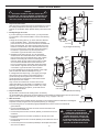
Coverage Area
The CS-350-N has a maximum range of 180 degrees and a coverage area of 600 sq. feet (56 sq.
meters). The sensor must have a clear and unobstructed view of the coverage area. Objects blocking
the sensor’s lens may prevent detection thereby causing the load (or loads) to turn OFF even though
someone is in the area.
Windows, glass doors, and other transparent barriers will obstruct the sensor’s view and prevent
detection.
Windows, glass doors, and other transparent barriers will obstruct the sensor’s view and prevent detection.
P
P
Fig. 1: Sensor Coverage Area

2
INSTALLATION & WIRING
1. Prepare the switch box.
After the power is turned OFF at the circuit breaker box, remove
the existing wall plate and mounting screws. Pull the two old
switches or combination switch (double switch) out from the wall
box.
2. Identify the type of circuit.
If you are replacing a combination switch, you may find that it
is connected to a circuit as described in A or B in the following
sections.
a. Single-circuit wiring (see Fig. 2): Three wires are attached
to the combination switch. The HOT feed wire bringing
power into the box is connected to the side of the switch that
has a connecting tab. The wires carrying power out to the
loads are connected to the side of the switch that does not
have a connecting tab. A neutral wire should be present in
the wall box. A ground wire may also be present and
connected to a ground terminal on the old switch.
b. Separate-circuit wiring (see Fig. 3): Four black wires
are attached to the combination switch. HOT feed wires
from the power source are attached to the side of switch
that has a connecting tab, and the connecting tab is
removed. Wires carrying power from the switch to loads
are connected to the side of the switch that does not
have a connecting tab. A neutral wire should be present
in the wall box. A ground wire may also be present and
connected to a ground terminal on the old switch.
If you are substituting two single pole switches, each single
pole circuit should match the description in Fig. 2.
In a Single Pole Circuit (see Fig. 5, next page), two single
wires connect to two screws on the existing switch. A
ground wire may also be present and connected to a
ground terminal on the old switch. A neutral wire should
also be present in the wall box.
Only connect the CS-350-N to one of the three circuit
options described. The CS-350-N is not suitable for 3-way
switching. If the existing wiring does not match any of the
previously described circuit options, you should consult
with a qualified electrician.
3. Prepare the Wires.
Tag the wires connected to the existing switch, so that they
can be identified later. Disconnect the wires. Make sure the insulation is stripped off the wires to expose their
copper cores to the length indicated by the “Strip Gauge” in Fig. 4 (approx. 1/2 inch).
4. Wire the sensor.*
Twist the existing wires together with the wire leads on the CS-350-N sensor as indicated in the diagram.
Cap them securely using the wire nuts provided (See Fig 6, next page).
a. Connect the green or non-isolated (copper) GROUND wire from the circuit to the CS-350-N
green terminal.
b. Connect the NEUTRAL wire from the circuit and from the loads to the
white wire on the CS-350-N.
c. Connect the power wire from circuit #1 (HOT#1) to the black wire on the
CS-350-N.
d. Connect the power wire to load #1 (LOAD#1) to the red wire on the
CS-350-N.
e. Connect the power wire from circuit #2 (HOT#2) to the solid brown wire on
the CS-350-N.
f. Connect the power wire to load #2 (LOAD#2) to the striped brown/white
wire on the CS-350-N.
WARNING
DISCONNECT POWER TO THE WALL SWITCH BOX
BY TURNING OFF THE CIRCUIT BREAKER OR REMOVING THE
FUSE FOR THE CIRCUIT BEFORE INSTALLING THE CS-350-N,
REPLACING LAMPS, OR DOING ANY ELECTRICAL WORK.
WIRES
TO
LOADS
NEUTRAL
WIRES
GROUND
WIRES
FEED WIRE
Fig. 2: Single-circuit wiring
WIRES
TO
LOADS
GROUND
WIRES
FEED WIRES
NEUTRAL
WIRES
Fig. 3: Separate-circuit wiring
Strip Gauge
1/2"
12.7mm
Fig. 4: Wire Stripping
CAUTION - FOR YOUR SAFETY:
CONNECTING A PROPER GROUND
TO THE SENSOR PROVIDES PROTECTION
AGAINST ELECTRICAL SHOCK IN THE
EVENT OF CERTAIN FAULT CONDITIONS.
IF A PROPER GROUND IS NOT AVAILABLE,
CONSULT WITH A QUALIFIED ELECTRICIAN
BEFORE CONTINUING INSTALLATION.

3
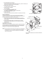
5. Put the CS-350-N in the wall box.
Position the lens above the ON/OFF buttons (lens at top, buttons at bottom) and
secure it to the wall box with the screws provided.
6. Restore power to the circuit.
Turn ON the breaker or replace the fuse.
7. Test the sensor’s operation.
See TEST MODE.
8. Review SENSOR ADJUSTMENT below.
If you want to make adjustments, follow the instructions in
the SENSOR ADJUSTMENT section.
9. Install cover plate.
Install industry standard decorator wall switch cover plate (not included).
Sensor Adjustment
To adjust the CS-350-N, you use a control located under the ON/OFF
buttons. The wall switch cover plate must be removed to gain access to the
time delay adjustment dial under the ON/OFF buttons.
1. Firmly grasp the side edges of the Lock Bar and gently pull it away
from the switch face until it clicks. Do NOT attempt to pull the Lock Bar
off of the switch!
2. Firmly grasp the outside edges of the ON/OFF buttons. Slide the
buttons downward approximately 1/2 inch to expose the time delay
adjustment dial.
Adjusting the Time Delay
Turn the dial counter-clockwise to reduce the amount of time both loads will
remain on after the last motion detection (minimum = 15 seconds). Turn the
same dial clockwise to increase this time delay (maximum = 30 minutes).
Warning: Do not overturn the time delay adjustment dial!
NOTE: These instructions assume wiring the CS-350-N to two independent
feed wires (HOTs). If you only have one HOT feed wire coming into
the wiring box, connect it to both the solid Brown and solid Black
wires on the CS-350-N.
Fig. 5: Typical Single Pole Switch Wiring
Ground
HOT (power from
circuit box)
LOAD
(power
to lamp)
NEUTRAL
TOP
IN DO OR USE ON LY
L
L
WV^LY[VSHTWVYMHU
Brown/White -> Load #2
Brown -> HOT
(power from circuit box for load #2)
>OP[L%5,<;9(3
9LK%36(+WV^LY
[VSHTWVYMHU
.YLLU%.96<5+
;LYTPUHS
)SHJR%/6;
WV^LYMYVTJPYJ\P[IV_
Fig. 6: Sensor orientation, wire connections and wall box
assembly

800.879.8585
www.legrand.us/wattstopper
No. 24263 – 05/18 rev. 1
© Copyright 2018 Legrand All Rights Reserved.
© Copyright 2018 Tous droits réservés Legrand.
© Copyright 2018 Legrand Todos los derechos reservados.
Wattstopper warranties its products to be free
of defects in materials and workmanship for a
period of five (5) years. There are no obligations
or liabilities on the part of Wattstopper for
consequential damages arising out of, or in
connection with, the use or performance of this
product or other indirect damages with respect
to loss of property, revenue or profit, or cost of
removal, installation or reinstallation.
Wattstopper garantit que ses produits sont
exempts de défauts de matériaux et de fabrication
pour une période de cinq (5) ans. Wattstopper
ne peut être tenu responsable de tout dommage
consécutif causé par ou lié à l’utilisation ou
à la performance de ce produit ou tout autre
dommage indirect lié à la perte de propriété, de
revenus, ou de profits, ou aux coûts d’enlèvement,
d’installation ou de réinstallation.
Wattstopper garantiza que sus productos
están libres de defectos en materiales y mano
de obra por un período de cinco (5) años. No
existen obligaciones ni responsabilidades por
parte de Wattstopper por daños consecuentes
que se deriven o estén relacionados con el
uso o el rendimiento de este producto u otros
daños indirectos con respecto a la pérdida
de propiedad, renta o ganancias, o al costo
de extracción, instalación o reinstalación.
WARRANTY INFORMATION INFORMATIONS RELATIVES À LA GARANTIE INFORMACIÓN DE LA GARANTÍA
-
 1
1
-
 2
2
-
 3
3
-
 4
4


wattstopper CS-350-N-W Mode d'emploi
- Taper
- Mode d'emploi
- Ce manuel convient également à
dans d''autres langues
Documents connexes
-
wattstopper RS-150BA-N-LA Mode d'emploi
-
Legrand RH-250 Multi-Way Wall Switch Occupancy Sensor (TriLingual) Mode d'emploi
-
Legrand RS-250-B Guide d'installation
-
wattstopper DT-205 Dual Technology Low Voltage Occupancy Sensor (TriLingual) Mode d'emploi
-
-
-
wattstopper LMIN 104 Guide d'installation