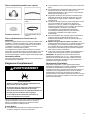
Maytag MGD6200KW Le manuel du propriétaire
- Catégorie
- Sèche-linge
- Taper
- Le manuel du propriétaire

GAS DRYER OWNER'S MANUAL
GUIDE D’UTILISATION DE LA SÉCHEUSE AU GAZ
W11361424A
W11361425A-SP
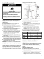
Table of Contents
Dryer Safety
........................................................... 2
Dryer Safety.......................................................2
Dryer Maintenance and Care ..................................5
Cleaning the Dryer Location
................................5
Cleaning the Dryer Interior
..................................5
Removing Accumulated Lint
................................5
Cleaning the Lint Screen
.....................................5
Changing the Drum Light (on some models)
.........6
Check Your Vent System for Good Airflow ............6
Maintain Good Airflow......................................... 6
Nonuse, Storage, and Moving Care
..................... 7
Special Instructions for Steam Models .................7
Installation Instructions..........................................7
Requirements
......................................................... 7
Tools and Parts
..................................................7
Location Requirements .......................................9
Gas Dryer Power Hookup – U.S.A. and
Canada
........................................................... 10
Gas Supply Requirements ................................ 10
Installation ........................................................... 11
Install Leveling Legs
......................................... 11
Make Gas Connection – U.S.A. and
Canada
........................................................... 12
Venting Requirements ...................................... 13
Plan Vent System
............................................. 13
Install Vent System ........................................... 15
Connect Inlet Hoses ......................................... 15
Connect Vent
................................................... 16
Level Dryer ...................................................... 16
Complete Installation Checklist.... ...................... 17
Sécurité de la sécheuse ....................................... 18
Sécurité de la sécheuse
.................................... 18
Entretien et réparation de la sécheuse ................. 21
Nettoyage de l’emplacement de la
sécheuse
......................................................... 21
Nettoyage de l’intérieur de la sécheuse.............. 21
Retrait de la charpie accumulée ........................ 21
Nettoyage du filtre à charpie.............................. 21
Changement de l’ampoule d’éclairage du
tambour (sur certains modèles)
......................... 22
Vérification d’une circulation d’air adéquate
pour le système d’évacuation
............................ 22
Pour maintenir une bonne circulation d’air
.......... 22
Précautions à prendre avant des
vacances, un entreposage ou un
déménagement
................................................ 23
Instructions spécifiques pour les modèles
vapeur
............................................................. 23
Instructions d’installation
..................................... 24
Spécifications
...................................................... 24
Outils et pièces
................................................ 24
Exigences d’emplacement ................................ 25
Raccordement électrique de la sécheuse à
gaz - états-unis et canada
................................. 26
Spécifications de l’alimentation en gaz
............... 27
L’installation
......................................................... 28
Exigences d’emplacement
................................ 28
Raccordement au gaz - états-unis et
canada
............................................................ 29
Exigences concernant l’évacuation
.................... 30
Planification des circuits de conduits.................. 31
Installation du conduit d’évacuation ................... 32
Raccordement des tuyaux d’alimentation ........... 32
Raccordement du conduit d’évacuation
.............. 34
Réglage de l’aplomb de la sécheuse.................. 34
Liste de vérification pour installation
terminée
.......................................................... 35
Table des matières

2
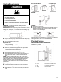
DRYER SAFETY
Your safety and the safety of others are very important.
We have provided many important safety messages in this manual and on your appliance. Always read and obey all safety
messages.
This is the safety alert symbol.
This symbol alerts you to potential hazards that can kill or hurt you and others.
All safety messages will follow the safety alert symbol and either the word “DANGER” or “WARNING.” These
words mean:
DANGER
You can be killed or seriously injured if you don't
immediately follow instructions.
WARNING
You can be killed or seriously injured if you don’t follow
instructions.
All safety messages will tell you what the potential hazard is, tell you how to reduce the chance of injury, and tell you what can
happen if the instructions are not followed.
IMPORTANT SAFETY INSTRUCTIONS
WARNING: To reduce the risk of fire, electric shock, or injury to persons when using your appliance, follow basic precautions,
including the following:
n Read all instructions before using the appliance.
n Do not dry articles that have been previously cleaned in,
washed in, soaked in, or spotted with gasoline, dry-cleaning
solvents, or other flammable or explosive substances, as
they give off vapors that could ignite or explode.
n Do not allow children to play on or in the appliance. Close
supervision of children is necessary when the appliance is
used near children.
n Before the appliance is removed from service or discarded,
remove the door to the drying compartment.
n Do not reach into the appliance if the drum is moving.
n Do not install or store this appliance where it will be
exposed to the weather.
n Do not tamper with controls.
n Do not repair or replace any part of the appliance or attempt
any servicing unless specifically recommended in the user-
maintenance instructions or in published user-repair
instructions that you understand and have the skills to carry
out.
n Do not use fabric softeners or products to eliminate static
unless recommended by the manufacturer of the fabric
softener or product.
n Do not use heat to dry articles containing foam rubber or
similarly textured rubber-like materials.
n Clean lint screen before or after each load.
n Keep area around the exhaust opening and adjacent
surrounding areas free from the accumulation of lint, dust,
and dirt.
n The interior of the appliance and exhaust duct should be
cleaned periodically by qualified service personnel.
n Do not place items exposed to cooking oils in your dryer.
Items contaminated with cooking oils may contribute to a
chemical reaction that could cause a load to catch fire. To
reduce the risk of fire due to contaminated loads, the final
part of a tumble dryer cycle occurs without heat (cool down
period). Avoid stopping a tumble dryer before the end of the
drying cycle unless all items are quickly removed and
spread out so that the heat is dissipated.
n Do not use replacement parts that have not been
recommended by the manufacturer (e.g. parts made at
home using a 3D printer).
n See the Installation Instructions for grounding requirements
and installation.
SAVE THESE INSTRUCTIONS

3
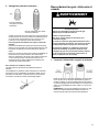
WARNING — “Risk of Fire”
− Clothes dryer installation must be performed by a qualified installer.
− Install the clothes dryer according to the manufacturer's instructions and local codes.
− Do not install a clothes dryer with flexible plastic venting materials or flexible metal (foil
type) duct. If flexible metal duct is installed, it must be of a specific type identified by
the appliance manufacturer as suitable for use with clothes dryers. Flexible venting
materials are known to collapse, be easily crushed, and trap lint. These conditions will
obstruct clothes dryer airflow and increase the risk of fire.
− To reduce the risk of severe injury or death, follow all installation instructions.
− Save these instructions.
WARNING
FIRE HAZARD
Failure to follow safety warnings exactly could result in serious injury, death, or property
damage.
Do not install a booster fan in the exhaust duct.
Install all clothes dryers in accordance with the installation instructions of the manufacturer
of the dryer.
WARNING:
FIRE OR EXPLOSION HAZARD
Failure to follow safety warnings exactly could result in serious injury, death, or property
damage.
− Do not store or use gasoline or other flammable vapors and liquids in the vicinity of this
or any other appliance.
− WHAT TO DO IF YOU SMELL GAS:
• Do not try to light any appliance.
• Do not touch any electrical switch; do not use any phone in your building.
• Clear the room, building, or area of all occupants.
• Immediately call your gas supplier from a neighbor’s phone. Follow the gas supplier’s
instructions.
• If you cannot reach your gas supplier, call the fire department.
− Installation and service must be performed by a qualified installer, service agency, or the
gas supplier.

4
WARNING: Gas leaks cannot always be detected by smell.
Gas suppliers recommend that you use a gas detector approved by UL or CSA.
For more information, contact your gas supplier.
If a gas leak is detected, follow the “What to do if you smell gas” instructions.
IMPORTANT: The gas installation must conform with local codes, or in the absence of local codes, with the National Fuel Gas Code,
ANSI Z223.1/NFPA 54, or the National Gas and Propane Installation Code, CSA B149.1.
The dryer must be electrically grounded in accordance with local codes, or in the absence of local codes, with the National Electrical
Code, ANSI/NFPA 70, or the Canadian Electrical Code, Part 1, CSA C22.1.
In the State of Massachusetts, the following installation instructions apply:
n Installation and repairs must be performed by a qualified or licensed contractor, plumber, or gas fitter qualified or licensed by the
State of Massachusetts.
n Acceptable Shut-off Devices: Gas Cocks and Ball Valves installed for use shall be listed.
n A flexible gas connector, when used, must not exceed 4 feet (121.9 cm).
IMPORTANT SAFETY INSTRUCTIONS
WHEN DISCARDING OR STORING YOUR OLD CLOTHES DRYER, REMOVE THE DOOR.
SAVE THESE INSTRUCTIONS

5
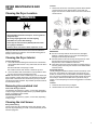
DRYER MAINTENANCE AND
CARE
Cleaning the Dryer Location
WARNING
Explosion Hazard
Keep flammable materials and vapors, such as gasoline,
away from dryer.
Do not dry anything that has ever had anything
flammable on it (even after washing).
Place dryer at least 18 inches (460 mm) above the floor
for a garage installation.
Failure to do so can result in death, explosion, or fire.
Keep dryer area clear and free from items that would block the
airflow for proper dryer operation. This includes clearing piles of
laundry in front of the dryer.
Cleaning the Dryer Interior
To clean dryer drum:
1. Use a mild hand dish detergent mixed at a low concentration
with nonflammable cleaner or very warm water, and rub with a
soft cloth.
n Rinse well with a wet sponge or towel.
n Tumble a load of clean clothes or towels to dry drum.
2. Use a microfiber cloth and hot water in a spray bottle to clean
the drum and a second microfiber towel to dry.
NOTE: Garments that contain unstable dyes, such as denim blue
jeans or brightly colored cotton items, may discolor the rear of the
dryer interior. These stains are not harmful to your dryer and will
not stain future loads of clothes. Dry unstable dye items inside out
to avoid transfer of dye.
Removing Accumulated Lint
From inside the dryer cabinet:
Lint should be removed every 2 years, or more often, depending
on dryer usage. Cleaning should be done by a qualified appliance
service or ventilation system cleaner.
From the exhaust vent:
Lint should be removed every 2 years, or more often, depending
on dryer usage.
Cleaning the Lint Screen
Every load cleaning:
The lint screen may be located either in the door opening or the
top of the dryer depending on model. A screen blocked by lint can
increase drying time.
To clean:
1. Remove the lint screen. If necessary, press the tab to release
and open the lint screen. Roll lint off the screen with your
fingers. Do not rinse or wash screen to remove lint. Wet lint is
hard to remove.
2. Push the lint screen firmly back into place.
IMPORTANT:
n Do not run the dryer with the lint screen loose, damaged,
blocked, or missing. Doing so can cause overheating and
damage to both the dryer and fabrics.
n If lint falls off the screen into the dryer during removal, check
the exhaust hood and remove the lint. See “Venting
Requirements” in the Installation Instructions.
n Clean space where lint screen is located, as needed. Using a
vacuum, gently remove any lint that has accumulated outside
of the lint screen.
As-needed cleaning:
Laundry detergent and fabric softener residue can build up on the
lint screen. This buildup can cause longer drying times for your
clothes, or cause the dryer to stop before your load is completely
dry. The screen is probably clogged if lint falls off while the screen
is in the dryer. Clean the lint screen with a nylon brush every 6
months, or more frequently, if it becomes clogged due to a residue
buildup.
To wash:
1. Roll lint off the screen with your fingers.
2. Wet both sides of lint screen with hot water.

6
3. Wet a nylon brush with hot water and liquid detergent. Scrub
lint screen with the brush to remove residue buildup.
4. Rinse screen with hot water.
5. Thoroughly dry lint screen with a clean towel. Reinstall screen
in dryer.
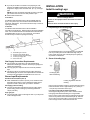
Changing the Drum Light (on some
models)
1. Unplug dryer or disconnect power.
2. Open the dryer door. Locate the light bulb cover on the back
wall of the dryer. Using a Phillips-head screwdriver or 1/4"
(6.35 mm) nut driver or socket wrench, remove the screw
located in the lower right-hand corner of the cover. Remove
the cover.
3. Turn bulb counterclockwise. Replace the bulb with a 10 W
appliance bulb only. Replace the cover and secure with the
screw.
4. Plug in dryer or reconnect power.
Accessories and replacement parts are available for your model.
For ordering and contact information, please reference your Quick
Start Guide.
Check Your Vent System for Good
Airflow
WARNING
Fire Hazard
Use a heavy metal vent.
Do not use a plastic vent.
Do not use a metal foil vent.
Failure to follow these instructions can result in death or
fire.
Good Airflow
Along with heat, dryers require good airflow to efficiently dry
laundry. Proper venting will reduce your drying times and improve
your energy savings. See Installation Instructions.
The venting system attached to the dryer plays a big role in good
airflow. Blocked or crushed vents as well as improper venting
installation will reduce air flow and dryer performance.
Service calls caused by improper venting are not covered by the
warranty and will be paid by the customer, regardless of who
installed the dryer. To clean or repair venting, contact a venting
specialist.
Maintain Good Airflow
n Cleaning your lint screen before each load.
n Replace plastic or foil vent material with 4" (102 mm) diameter
heavy, rigid vent material.
n Use the shortest length of vent possible.
n Use no more than four 90° elbows in a vent system; each bend
and curve reduces airflow.
n Remove lint and debris from the exhaust hood.
n Remove lint from the entire length of the vent system at least
every 2 years. When cleaning is complete, be sure to follow
the Installation Instructions for final product check.
n Clear away items from the front of the dryer.

7
Nonuse, Storage, and Moving Care
Install and store your dryer where it will not freeze. Because some
water may stay in the hose, freezing can damage your dryer. If
storing or moving your dryer during freezing weather, winterize it.
Nonuse or Storage Care
If you will be on vacation or not using your dryer for an extended
period of time, you should:
1. Unplug dryer or disconnect power.
2. Clean lint screen. See “Cleaning the Lint Screen.”
3. Close shutoff valve in gas supply line.
4. Turn off the water supply to the dryer. This helps to avoid
unintended flooding (due to a water pressure surge) while you
are away.
Moving Care
1. Unplug the power supply cord.
2. Gas models only: Close shutoff valve in gas supply line.
3. Gas models only: Disconnect gas supply line pipe and remove
fittings attached to dryer pipe.
4. Gas models only: Cap the open gas supply line.
5. Steam models only: Shut off water faucet. Disconnect the
water inlet hose from faucet; then drain the hose. Transport
hose separately.
6. Make sure leveling legs are secure in dryer base.
7. Use tape to secure dryer door.
8. On models with base trim, remove base trim before moving
dryer. See “Install and remove base trim (on some models)”
for details.
Special Instructions for Steam
Models
Water Inlet Hose
Replace inlet hose and hose screen after 5 years of use to reduce
the risk of hose failure. Periodically inspect and replace inlet hose
if bulges, kinks, cuts, wear, or leaks are found.
When replacing your inlet hose, record the date of replacement.
To winterize the dryer:
1. Unplug dryer or disconnect power.
2. Shut off water faucet.
3. Disconnect water inlet hose from faucet and drain.
To use the dryer again:
WARNING
Electrical Shock Hazard
Plug into a grounded 3 prong outlet.
Do not remove ground prong.
Do not use an adapter.
Do not use an extension cord.
Failure to follow these instructions can result in death,
fire, or electrical shock.
1. Flush water pipes. Reconnect water inlet hose to faucet. Turn
on water faucet.
2. Plug in dryer or reconnect power as described in the
Installation Instructions.
Reinstalling the Dryer
Follow the Installation Instructions to locate, level, and connect the
dryer.
INSTALLATION INSTRUCTIONS
REQUIREMENTS
Tools and Parts
NOTE: Install the clothes dryer according to the manufacturer’s
instructions and local codes.
Gather required tools and parts before starting installation. Read
and follow the instructions provided with any tools listed here.
Tools Needed for All Installations:
Flat-blade screwdriver
#2 Phillips screwdriver
1/4" and 5 /16" nut driver
Level

8
Pliers or slip-joint pliers
Tape measure
Utility knife
Tin snips (new vent
installations)
Caulking gun and compound
(new vent installations)
Adjustable wrench that opens
to 1" (25 mm) or hex-head
socket wrench
Vent clamps
Putty knife
8" (203 mm) or 10" (254 mm)
pipe wrench
Wire stripper (direct-wire
installations)
Pipe-joint compound resistant
to propane gas
Parts Supplied (all models):
Leveling legs (4) (Length and appearance of legs may vary
according to model)
Parts package is located in dryer drum. Check that all parts are
included.
NOTE: Do not use leveling legs supplied with dryer if installing
with a pedestal or a stack kit.
Parts Needed (steam models):
“Y” connector
2' (0.6 m) inlet hose
Rubber washer
5' (1.52 m) inlet hose
Parts Needed (not supplied with dryer):
Additional parts may be required, depending on your installation.
Check local codes. Check existing electrical supply and venting.
See “Electrical Requirements” and “Venting Requirements” before
purchasing parts.
Mobile home installations require metal exhaust system hardware
available for purchase from the dealer from whom you purchased
your dryer. For further information, please refer to the Quick Start
Guide for service contact information.
Available Accessories:
Refer to your Quick Start Guide for contact and ordering
information.

9
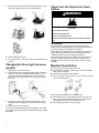
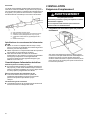
Location Requirements
WARNING
Explosion Hazard
Keep flammable materials and vapors, such as gasoline,
away from dryer.
Do not dry anything that has ever had anything
flammable on it (even after washing).
Place dryer at least 18 inches (460 mm) above the floor
for a garage installation.
Failure to do so can result in death, explosion, or fire.
Check code requirements. Some codes limit, or do not permit,
installation of the dryer in garages, closets, mobile homes, or
sleeping quarters. Contact your local building inspector.
You will need:
n A location allowing for proper exhaust installation. See
“Venting Requirements.”
n A separate 15 A or 20 A circuit for gas dryers.
n A grounded electrical outlet located within 2 ft. (610 mm) of
either side of the dryer. See “Electrical Requirements” in the
“Gas Dryer Power Hookup” section.
n A sturdy floor to support dryer and a total weight (dryer and
load) of 200 lbs. (90.7 kg). The combined weight of a
companion appliance should also be considered.
n Level floor with maximum slope of 1" (25 mm) under entire
dryer. If slope is greater than 1" (25 mm), install Extended
Dryer Feet Kit. If not level, clothes may not tumble properly
and automatic sensor cycles may not operate correctly.
Installing on carpet is not recommended.
n For garage installation, place dryer at least 18" (460 mm)
above floor. If using a pedestal, you will need 18" (460 mm) to
bottom of dryer.
n Steam models only: Cold water faucets located within 4 ft.
(1.2 m) of the water fill valves, and water pressure of 20–100
psi (137.9–689.6 kPa). You may use your washer’s water
supply by utilizing the necessary parts noted in “Parts needed.”
n The dryer must not be installed or stored in an area where it
will be exposed to water and/or weather.
IMPORTANT: Do not operate your dryer at temperatures below
45°F (7°C). Lower temperatures may cause dryer not to shut off
at end of automatic sensor cycles, resulting in longer drying times.
Installation clearances:
For each arrangement, consider allowing more space for ease of
installation and servicing, spacing for companion appliances, and
clearances for walls, doors, and floor moldings. Space must be
large enough to allow the door to fully open. Add spacing on all
sides of dryer to reduce noise transfer. If a closet door or louvered
door is installed, top and bottom air openings in door are required.
Spacing for recessed area or closet
NOTE: No other fuel-burning appliance can be installed in the
same closet as a dryer.
The dimensions shown are for the minimum spacing allowed.
n Additional spacing should be considered for ease of
installation and servicing.
n Additional clearances might be required for wall, door, and
floor moldings.
n Additional spacing of 1" (25 mm) on all sides of the dryer is
recommended to reduce noise transfer.
n For closet installation with a door, minimum ventilation
openings in the top and bottom of the door are required.
Louvered doors with equivalent ventilation openings are
acceptable.
n Companion appliance spacing should also be considered.
Minimum installation clearances (dryer only):
Front Sides Rear Top
Recessed NA 0" (0 mm) 0" (0 mm) 0" (0 mm)
Closet NA 0" (0 mm) 0" (0 mm) 0" (0 mm)
Under
Counter
NA 1" (25 mm) 0" (0 mm) 0" (0 mm)
0" (0 mm) rear spacing is allowed for straight-back venting only.
For steam models only, inlet hose must not be kinked.
Mobile Home – Additional installation
requirements
This dryer is suitable for mobile home installations. The
installation must conform to the Manufactured Home Construction
and Safety Standard, Title 24 CFR, Part 3280 (formerly the
Federal Standard for Mobile Home Construction and Safety, Title
24, HUD Part 280) or the Standard for Mobile Homes, CAN/CSA-
Z240 MH.
Mobile home installations require:
n Metal exhaust system hardware, which is available for
purchase from your dealer.
n Mobile Home Installation Hold-Down Kit. See your Quick Start
Guide for more information.
n Special provisions must be made in mobile homes to introduce
outside air into the dryer. The opening (such as a nearby
window) should be at least twice as large as the dryer exhaust
opening.

10
Gas Dryer Power Hookup – U.S.A.
and Canada
Electrical Requirements
WARNING
Electrical Shock Hazard
Plug into a grounded 3 prong outlet.
Do not remove ground prong.
Do not use an adapter.
Do not use an extension cord.
Failure to follow these instructions can result in death,
fire, or electrical shock.
120 V, 60 Hz, AC-only, 15 A or 20 A fused electrical supply is
required. A time-delay fuse or circuit breaker is recommended. It
is also recommended that a separate circuit serving only this dryer
be provided. Do not use an extension cord.
GROUNDING INSTRUCTIONS
For a grounded, cord-connected appliance:
This appliance must be grounded. In the event of a
malfunction or breakdown, grounding will reduce the risk of
electric shock by providing a path of least resistance for
electric current. This appliance is equipped with a cord having
an equipment-grounding conductor and a grounding plug.
The plug must be plugged into an appropriate outlet that is
properly installed and grounded in accordance with all local
codes and ordinances.
WARNING: Improper connection of the equipment-
grounding conductor can result in a risk of electric shock.
Check with a qualified electrician or serviceman if you are in
doubt as to whether the appliance is properly grounded. Do
not modify the plug provided with the appliance: if it will not fit
the outlet, have a proper outlet installed by a qualified
electrician.
SAVE THESE INSTRUCTIONS
Gas Supply Requirements
WARNING
Explosion Hazard
Use a new CSA International approved gas supply line.
Install a shut-off valve.
Securely tighten all gas connections.
If connected to propane, have a qualified person make
sure gas pressure does not exceed 13ʺ (33 cm) water
column.
Examples of a qualified person include: licensed heating
personnel, authorized gas company personnel, and
authorized service personnel.
Failure to do so can result in death, explosion, or fire.
Gas Type
Natural Gas:
This dryer is equipped for use with natural gas. It is certified by UL
for use with propane gas with appropriate conversion.
n Your dryer must have the correct burner for the type of gas in
your home. Burner information is located on the rating plate in
the door well of your dryer. If this information does not agree
with the type of gas available, contact your dealer or reference
the contact information listed on your Quick Start Guide.
Propane Gas Conversion:
IMPORTANT: Conversion must be made by a qualified technician.
No attempt shall be made to convert the appliance from the gas
specified on the model/serial rating plate for use with a different
gas without consulting your gas company.
Gas Supply Line
Option 1 (Recommended Method)
Flexible stainless steel gas connector:
n If local codes permit, use a new flexible stainless steel gas
connector (Design-Certified by the American Gas Association
or CSA International) to connect your dryer to the rigid gas
supply line. Use an elbow and a 3/8" flare x 3/8" NPT adapter
fitting between the stainless steel gas connector and the dryer
gas pipe, as needed, to prevent kinking.
Option 2 (Alternate Method)
Approved aluminum or copper tubing:
n Must include 1/8" NPT minimum plugged tapping accessible
for test gauge connection, immediately upstream of the gas
connection to the dryer.
n 1/2" IPS pipe is recommended.
n 3/8" approved aluminum or copper tubing is acceptable for
lengths under 20 ft. (6.1 m) if local codes and gas supplier
permit.
n If you are using natural gas, do not use copper tubing.
n Lengths over 20 ft. (6.1 m) should use larger tubing and a
different size adapter fitting.

11
n If your dryer has been converted to use propane gas, 3/8"
propane-compatible copper tubing can be used. If the total
length of the supply line is more than 20 ft. (6.1 m), use larger
pipe.
NOTE: Pipe-joint compounds that resist the action of propane
gas must be used. Do not use PTFE plumber’s tape.
n Must include shutoff valve.
In the U.S.A.:
An individual manual shutoff valve must be installed within six
(6) ft. (1.8 m) of the dryer in accordance with the National Fuel
Gas Code, ANSI Z223.1. The location should be easy to reach for
opening and closing.
In Canada:
An individual manual shutoff valve must be installed in
accordance with the B149.1, Natural Gas and Propane Installation
Code. It is recommended that an individual manual shutoff valve
be installed within six (6) ft. (1.8 m) of the dryer. The location
should be easy to reach for opening and closing.
A. 3/8" flexible gas connector
B. 3/8" pipe-to-flare adapter fitting
C. 1/8" NPT minimum plugged tapping
D. 1/2" NPT gas supply line
E. Gas shutoff valve
Gas Supply Connection Requirements
n Use an elbow and a 3/8" flare x 3/8" NPT adapter fitting
between the flexible gas connector and the dryer gas pipe, as
needed to avoid kinking.
n Use only pipe-joint compound. Do not use PTFE plumber’s
tape.
n This dryer must be connected to the gas supply line with a
listed flexible gas connector that complies with the standard for
connectors for gas appliances, ANSI Z21.24 or CSA 6.10.
Burner Input Requirements
Elevations above 2,000 ft. (610 m)
n When installed above 2,000 ft. (610 m), a 4% reduction of the
burner Btu rating shown on the model/serial number plate is
required for each 1,000 ft. (305 m) increase in elevation.
Gas supply pressure testing
n The dryer must be disconnected from the gas supply piping
system during pressure testing at pressures greater than
1/2 psi (3.45 kPa).
Dryer gas pipe
n The gas pipe that comes out through the rear of your dryer has
a 3/8" male pipe thread.
INSTALLATION
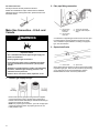
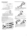
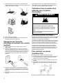
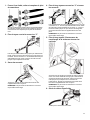
Install Leveling Legs
WARNING
Excessive Weight Hazard
Use two or more people to move and install or uninstall
appliance.
Failure to do so can result in back or other injury.
1. Prepare dryer for leveling legs
To avoid damaging floor, use a large flat piece of cardboard
from dryer carton; place under entire back edge of dryer.
Firmly grasp dryer body (not console panel) and gently lay
dryer down on cardboard.
2. Screw in leveling legs
Leveling leg with
diamond marking
Leveling leg without diamond
marking
Using a wrench and tape measure, screw leveling leg into leg
holes until bottom of foot is approximately 1/2" (13 mm) to
1 1/2" (38 mm) from bottom of the dryer.
For leveling legs with the diamond marking:
Screw legs into leg holes by hand. Use a wrench to finish
turning legs until diamond marking is no longer visible.
Place a carton corner post from dryer packaging under each
of the two dryer back corners. Stand the dryer up. Slide the
dryer on the corner posts until it is close to its final location.
Leave enough room to connect the exhaust vent.

12
For mobile home use:
Gas dryers must be securely fastened to the floor.
Mobile home installations require a Mobile Home Installation
Hold-Down Kit. For ordering information, please reference the
Quick Start Guide.
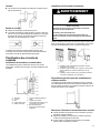
Make Gas Connection – U.S.A. and
Canada
WARNING
Explosion Hazard
Use a new CSA International approved gas supply line.
Install a shut-off valve.
Securely tighten all gas connections.
If connected to propane, have a qualified person make
sure gas pressure does not exceed 13ʺ (33 cm) water
column.
Examples of a qualified person include: licensed heating
personnel, authorized gas company personnel, and
authorized service personnel.
Failure to do so can result in death, explosion, or fire.
1. Connect gas supply to dryer
Remove red cap from gas pipe. Using a wrench to tighten,
connect gas supply to dryer. Use pipe-joint compound on
threads of all non-flared male fittings. If flexible metal tubing is
used, be sure there are no kinks.
NOTE: For propane gas connections, you must use pipe-joint
compound resistant to action of propane gas. Do not use
PTFE plumber’s tape.
2. Plan pipe fitting connection
A. 3/8" (9.5 mm)
flexible gas
connector
B. 3/8" (9.5 mm)
dryer pipe
C. 3/8" to 3/8" pipe elbow
D. 3/8" pipe-to-flare adapter
fitting
A combination of pipe fittings must be used to connect dryer
to existing gas line. Recommended connection is shown.
Your connection may be different, according to supply line
type, size, and location.
3. Open shutoff valve
A. Closed valve B. Open valve
Open shutoff valve in supply line; valve is open when handle
is parallel to gas pipe. Then, test all connections by brushing
on an approved noncorrosive leak-detection solution.
Bubbles will show a leak. Correct any leaks found.

13
Venting Requirements
WARNING
Fire Hazard
Use a heavy metal vent.
Do not use a plastic vent.
Do not use a metal foil vent.
Failure to follow these instructions can result in death or
fire.
WARNING: To reduce the risk of fire, this dryer MUST BE
EXHAUSTED OUTDOORS.
IMPORTANT: Observe all governing codes and ordinances. Dryer
exhaust must not be connected into any gas vent, chimney, wall,
ceiling, attic, crawlspace, or a concealed space of a building. Only
rigid or flexible metal vent shall be used for exhausting.
n Only a 4" (102 mm) heavy metal exhaust vent and clamps may
be used.
n Do not use plastic or metal foil vent.
Rigid metal vent:
n Recommended for best drying performance and to avoid
crushing and kinking.
Flexible metal vent (acceptable only if accessible to clean):
n Must be fully extended and supported in final dryer location.
n Remove excess to avoid sagging and kinking that may result
in reduced airflow and poor performance.
n Do not install in enclosed walls, ceilings, or floors.
n The total length should not exceed 7 3/4 ft. (2.4 m).
n The length of flexible metal vent used must be included in the
overall vent system design as shown in the “Vent System
Chart.”
NOTE: If using an existing vent system, clean lint from entire
length of the system and make sure exhaust hood is not plugged
with lint. Replace plastic or metal foil vents with rigid metal or
flexible metal vents. Review “Vent System Chart” and, if
necessary, modify existing vent system to achieve best drying
performance.
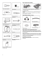
Exhaust hoods:
n An exhaust hood should cap the vent to keep rodents and
insects from entering the home.
n Must be at least 12" (305 mm) from ground or any object that
may obstruct exhaust (such as flowers, rocks, bushes, or
snow).
n Do not use an exhaust hood with a magnetic latch.
Recommended Styles: Acceptable Style:
Louvered Hood
Box Hood
Angled Hood
Elbows:
n 45° elbows provide better airflow than 90° elbows.
Clamps:
n Use clamps to seal all joints.
n Exhaust vent must not be connected or secured with screws or
other fastening devices that extend into interior of duct and
catch lint. Do not use duct tape.
Vent products can be purchased from your dealer. For contact and
ordering information, refer to your Quick Start Guide.
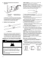
Plan Vent System
Recommended exhaust installations:
Typical installations vent the dryer from the rear of the dryer. Other
installations are possible.
A. Dryer
B. Elbow
C. Wall
D. Exhaust hood
E. Clamps
F. Rigid metal or flexible metal
vent
G. Vent length necessary to
connect elbows
H. Exhaust outlet
I. Optional side exhaust outlet

14
Optional exhaust installations:
WARNING
Fire Hazard
Cover unused exhaust holes with a manufacturer’s
exhaust cover kit.
Contact your local dealer.
Failure to follow these instructions can result in death,
fire, electrical shock, or serious injury.
Some models can be converted to exhaust out the right side, left
side, or through the bottom. If you prefer, you may contact your
local dealer to have the dryer converted.
A. Standard rear offset exhaust installation
B. Left- or right-side exhaust installation (available only on
select 27"-wide models).
C. Bottom exhaust installation (available only on select 27"-
wide models).
Special provisions for mobile home installations:
Exhaust vent must be securely fastened to a noncombustible
portion of the mobile home and must not terminate beneath the
mobile home. Terminate exhaust vent outside.
Determine vent path:
n Select route that will provide straightest and most direct path
outdoors.
n Plan installation to use fewest number of elbows and turns.
n When using elbows or making turns, allow as much room as
possible.
n Bend vent gradually to avoid kinking.
n Use as few 90° turns as possible.
Determine vent length and elbows needed for best
drying performance:
n Use the following “Vent System Chart” to determine the type of
vent material and hood combinations acceptable to use.
NOTE: Do not use vent that runs longer than those specified in
the “Vent System Chart.” Exhaust systems longer than those
specified will:
n Shorten life of dryer.
n Reduce performance, resulting in longer drying times and
increased energy usage.
The “Vent System Charts” provide venting requirements that will
help achieve best drying performance.
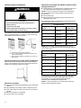
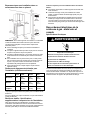
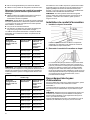
Vent System Chart
Number of 90°
elbows
Type of vent Box/louvered or
Angled hoods
0 Rigid metal 64 ft. (20 m)
1 Rigid metal 54 ft. (16.5 m)
2 Rigid metal 44 ft. (13.4 m)
3 Rigid metal 35 ft. (10.7 m)
4 Rigid metal 27 ft. (8.2 m)
NOTE: Side and bottom exhaust installations have a 90º turn
inside the dryer. To determine maximum exhaust length, add one
90º turn to the chart.
Vent System Chart (Long Vent Models)
Number of 90°
elbows
Type of vent Box/louvered or
angled hoods
0 Rigid metal 160 ft. (48.8 m)
1 Rigid metal 150 ft. (45.7 m)
2 Rigid metal 140 ft. (42.7 m)
3 Rigid metal 130 ft. (39.6 m)
4 Rigid metal 120 ft. (36.6 m)
5 Rigid metal 110 ft. (33.5 m)
To determine if your model has a long vent system, refer to the
type code located on the serial number plate in the inner door
well. Example: A Long Vent Model would be BJAV-NAT-
XXXXXXX-XXX or BWFB-NAT-XXXXXXX-XXX.
NOTE: For long vent systems, use of box/louvered hoods will
improve venting regardless of length.

15
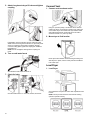
Install Vent System
1. Install exhaust hood
Install exhaust hood and use caulking compound to seal
exterior wall opening around exhaust hood.
2. Connect vent to exhaust hood
Vent must fit over the exhaust hood. Secure vent to exhaust
hood with 4" (102 mm) clamp. Run vent to dryer location
using straightest path possible. Avoid 90° turns. Use clamps
to seal all joints. Do not use duct tape, screws, or other
fastening devices that extend into interior of vent to secure
vent, because they can catch lint.
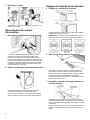
Connect Inlet Hoses
For vented, non-steam models, skip to “Connect Vent.”
The dryer must be connected to the cold water faucet using the
new inlet hoses. Do not use old hoses.
NOTE: Replace inlet hoses after 5 years of use to reduce the risk
of hose failure. Record hose installation or replacement dates on
the hoses for future reference.
Periodically inspect and replace hoses if bulges, kinks, cuts, wear,
or leaks are found.
1. Turn cold water off, remove and replace rubber
washer
Turn cold water faucet off and remove washer inlet hose.
Remove old rubber washer from inlet hose and replace with
new rubber washer.
2. Attach short hose and “Y” connector
Attach 2 ft. (0.6 m) inlet hose to cold water faucet. Screw on
coupling by hand until it is seated on faucet. Then attach “Y”
connector to male end of the 2 ft. (0.6 m) inlet hose. Screw on
coupling by hand until it is seated on connector.
3. Tighten couplings
Using pliers, tighten the couplings with additional two-thirds
turn.
NOTE: Do not overtighten. Damage to the coupling can
result.
4. Attach long hose to “Y” connector and tighten
couplings
Attach one of the 5 ft. (1.5 m) inlet hose ends to the “Y”
connector. Attach washer cold inlet hose to other side of “Y”
connector. Screw on coupling by hand until it is seated on
connector. Using pliers, tighten the couplings an additional
two-thirds turn.
NOTE: Do not overtighten. Damage to the coupling can
result.

16
5. Attach long hose to dryer fill valve and tighten
coupling
If applicable, remove protective cap from water inlet valve.
Attach other end of long hose to fill valve on dryer back panel.
Screw on coupling by hand until it is seated on fill valve
connector. Using pliers, tighten the couplings an additional
two-thirds turn.
NOTE: Do not overtighten. Damage to the coupling can
result.
6. Turn on cold water faucet
Check that the water faucet is turned on.
7. Check for leaks
Check for leaks around “Y” connector, faucets, and hoses.
Connect Vent
1. Connect vent to exhaust outlet
Using a 4" (102 mm) clamp, connect the vent to exhaust
outlet in the dryer. If connecting to existing vent, make sure
vent is clean. Dryer vent must fit over dryer exhaust outlet
and inside exhaust hood. Check that vent is secured to
exhaust hood with a 4" (102 mm) clamp.
2. Move dryer to final location
Move dryer to final location. Avoid crushing or kinking vent.
After dryer is in place, remove corner posts and cardboard
from under dryer.
Level Dryer
1. Level Dryer
Check levelness of dryer from side to side. Repeat from front
to back.
NOTE: The dryer must be level for the moisture-sensing
system to operate correctly.

17
2. Tighten and adjust leveling legs
If dryer is not level, prop up using a wood block. Use wrench
to adjust legs up or down, and check again for levelness.
Once dryer is level, make sure all four legs are snug against
the floor and the dryer does not rock.
3. Install and remove base trim (on some models)
To Install: Place the skirt to bottom of dryer and match the
locating pins with the holes. Press the skirt firmly upwards
until it snaps into place.
To Remove: On each corner, push down on top of base trim.
Rotate away from dryer and remove.
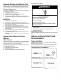
Complete Installation Checklist
q Check that all parts are now installed. If there is an extra part,
go back through steps to see what was skipped.
q Check that you have all of your tools.
q Dispose of/recycle all packaging materials.
q Check dryer’s final location. Be sure vent is not crushed or
kinked.
q Check that dryer is level. See “Level Dryer.”
q Remove film on console and any tape remaining on dryer.
q Wipe dryer drum interior thoroughly with a damp cloth to
remove any dust.
q Refer to the user instructions in your Quick Start Guide.
WARNING
Electrical Shock Hazard
Plug into a grounded 3 prong outlet.
Do not remove ground prong.
Do not use an adapter.
Do not use an extension cord.
Failure to follow these instructions can result in death,
fire, or electrical shock.
Gas Models:
q Plug into a grounded 3 prong outlet.
q Check that gas supply is on.
q Check for leaks.
q Check that the flexible gas line is not crushed or kinked.
Steam Models Only:
q Be sure the water faucets are on.
q Check for leaks around “Y” connector, faucet, and hoses.
q If you live in a hard water area, use of a water softener is
recommended to control the buildup of scale through the water
system in the dryer. Over time, the buildup of lime scale may
clog different parts of the water system, which will reduce
product performance. Excessive scale buildup may lead to the
need for certain part replacement or repair.
All Models:
q Set the heat cycle for 20 minutes and start dryer. Do not select
Air Only temperature setting.
If dryer will not start, check the following:
n Controls are set in a running or “ON” position.
n Start button has been pressed firmly.
n Dryer is plugged into an outlet and/or electrical supply is
connected.
n Household fuse is intact and tight, or circuit breaker has not
tripped.
n Dryer door is closed.
q When the dryer has been running for 5 minutes, open the dryer
door and feel for heat. If you feel heat, cancel cycle and close
the door.
If you do not feel heat, turn the dryer off and check to see
whether gas supply shutoff valve is open.
q If the gas supply shutoff valve is closed, open it and then
repeat the 5-minute test as outlined above.
q If the gas supply line shutoff valve is open, contact a qualified
technician.
n To change the door swing from a right-side opening to a left-
side opening, see online “Dryer Door Reversal Instructions” for
details.
If your Airflow screen reads “Check Vent,” your dryer vent may be
crushed or blocked.
NOTE: You may notice an odor when dryer is first heated. This
odor is common when heating element is first used. The odor will
go away.

18
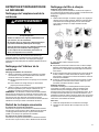
SÉCURITÉ DE LA SÉCHEUSE
Votre sécurité et celle des autres est très importante.
Nous donnons de nombreux messages de sécurité importants dans ce manuel et sur votre appareil ménager. Assurez-vous de
toujours lire tous les messages de sécurité et de vous y conformer.
Voici le symbole d’alerte de sécurité.
Ce symbole d’alerte de sécurité vous signale les dangers potentiels de décès et de blessures graves à vous et à
d’autres.
Tous les messages de sécurité suivront le symbole d’alerte de sécurité et le mot “DANGER” ou
“AVERTISSEMENT”. Ces mots signifient :
DANGER
Risque possible de décès ou de blessure grave si vous ne
suivez pas immédiatement les instructions.
AVERTISSEMENT
Risque possible de décès ou de blessure grave si vous ne
suivez pas les instructions.
Tous les messages de sécurité vous diront quel est le danger potentiel et vous disent comment réduire le risque de blessure et ce
qui peut se produire en cas de non-respect des instructions.
IMPORTANTES INSTRUCTIONS DE SÉCURITÉ
AVERTISSEMENT : Afin de réduire le risque d’incendie, de décharge électrique ou de blessures corporelles lors de l’utilisation
de cet appareil, observer certaines précautions fondamentales, notamment :
n Lire toutes les instructions avant d’utiliser l’appareil.
n Ne pas sécher d’articles qui ont été précédemment
nettoyés, lavés, trempés ou tachés avec de l’essence, des
solvants pour nettoyage à sec ou d’autres substances
inflammables ou explosives; ces substances dégagent des
vapeurs qui pourraient s’enflammer ou exploser.
n Ne laissez pas les enfants jouer sur ou dans la sécheuse.
Une surveillance attentive s’impose lorsqu’on utilise
l'appareil ménager à proximité d’enfants.
n Avant de retirer ou de jeter le sèche-linge, retirez la porte
du compartiment de séchage.
n Ne pas mettre la main dans la sécheuse si le tambour est
en mouvement.
n Ne pas installer ni entreposer la sécheuse où elle sera
exposée aux intempéries.
n Ne pas effectuer d’intervention non autorisée sur les
commandes.
n Ne pas réparer ou remplacer une quelconque pièce de
l’appareil ou effectuer un entretien qui ne serait pas
expressément recommandé dans les instructions
d’entretien de l’utilisateur ou dans les instructions de
réparation par l’utilisateur et s’assurer de bien comprendre
ces instructions et d’être capable de les exécuter.
n Ne pas utiliser d’assouplissant ou de produits pour éliminer
l’électricité statique à moins que cela ne soit recommandé
par le fabricant de l’assouplissant ou du produit.
n Ne pas sécher à la chaleur des articles contenant du
caoutchouc mousse ou des matières similaires.
n Nettoyer le filtre à charpie avant ou après chaque charge.
n La zone située autour de l’ouverture d’évacuation et les
zones adjacentes doivent être propres, exemptes de
peluches et poussières.
n Un nettoyage periodique de l'interieur de la secheuse at du
conduit d'evacation etre effectue par une personne
qualifiee.
n Ne pas placer d’articles tâchés d’huile de cuisson dans la
sécheuse. Les articles couverts d’huile de cuisson peuvent
provoquer une réaction chimique et enflammer la charge
de vêtements. Pour réduire le risque d’incendie dû à des
charges contaminées, la partie finale du programme de
séchage par culbutage a lieu sans chaleur (période de
refroidissement). Éviter d’arrêter une sécheuse en phase
de culbutage avant la fin du programme de séchage, à
moins de retirer et d’étendre rapidement tous les articles
afin que la chaleur se dissipe.
n Ne pas utiliser de pièces de remplacement qui n’ont pas
été recommandées par le fabricant (c.-à-d., pièces
fabriquées à la maison à l’aide d’une imprimante 3D).
n Voir les instructions d’installation pour les exigences de
mise à la terre et d’installation.
CONSERVER CES INSTRUCTIONS

19
AVERTISSEMENT — “risque d’incendie”
− L’installation de la sécheuse à linge doit être effectuée par un installateur qualifié.
− Installer la sécheuse conformément aux instructions du fabricant et aux codes locaux.
− Ne pas installer la sécheuse avec des matériaux d’évacuation en plastique souple ou
un conduit métallique souple (type aluminium). Si un conduit métallique souple est
installé, celui-ci doit être d’un type spécifique identifié par le fabricant de l'appareil et
convenir à une utilisation avec les sécheuses à linge. Les matériaux d'évacuation
souples sont connus pour s'affaisser, être facilement écrasés et piéger la charpie. Ces
situations obstrueront le débit d’air de la sécheuse et augmenteront le risque
d’incendie.
− Pour réduire le risque de blessure grave ou de décès, suivre toutes les instructions
d’installation.
− Conserver ces instructions.
AVERTISSEMENT
Risque d'incendie
Le non-respect des avertissements de sécurité peut causer des dommages à la propriété,
des blessures graves, voire la mort.
Ne pas installer de ventilateur d’appoint dans le conduit d’évacuation.
Installer toutes les sécheuses en respectant les instructions d’installation du fabricant de la
sécheuse.
AVERTISSEMENT :
RISQUE D’INCENDIE OU D’EXPLOSION
Le non-respect des avertissements de sécurité peut causer des dommages à la propriété,
des blessures graves, voire la mort.
− Ne pas entreposer ou utiliser d’essence ou tout autre liquide ou gaz inflammable à
proximité de cet appareil ou de tout autre appareil.
− QUE FAIRE EN CAS DE DÉTECTION D’UNE ODEUR DE GAZ :
• Ne mettre en marche aucun appareil.
• Ne pas entrer en contact avec un interrupteur électrique; ne pas utiliser un quelconque
téléphone à l'intérieur du bâtiment.
• Faire évacuer la pièce, l’immeuble ou la zone de tous les occupants.
• Appeler immédiatement le fournisseur de gaz à partir du téléphone d’un voisin. Suivre
les instructions du fournisseur de gaz.
• Si le fournisseur de gaz n’est pas joignable, appeler les pompiers.
− L’installation et la réparation doivent être effectuées par un installateur ou une entreprise
de réparation ayant les qualifications requises ou par le fournisseur de gaz.

20
AVERTISSEMENT : Les fuites de gaz ne peuvent pas toujours être détectées à l’odorat.
Les fournisseurs de gaz recommandent d’utiliser un détecteur de gaz approuvé UL ou CSA.
Pour plus d’informations, contacter votre fournisseur de gaz.
Si une fuite de gaz est détectée, suivre les instructions de la section « Que faire en cas de détection d’une odeur de gaz ».
IMPORTANT: L’installation au gaz doit être conforme aux codes locaux, ou en l’absence de codes locaux, au Code National
d’alimentation au gaz, à la norme ANSI Z223.1/NFPA 54 ou au Code des installations au gaz naturel et au propane, Code, CSA
B149.1.
La sécheuse doit être correctement reliée à la terre en conformité avec les codes locaux en vigueur, ou en l’absence de tels codes,
avec le National Electrical Code, ANSI/NFPA 70 ou le Code canadien des installations électriques, CSA C22.1 partie 1.
Dans l’État du Massachusetts, les instructions d’installation suivantes sont applicables :
n Les travaux d’installation et réparation doivent être exécutés par un plombier ou monteur d’installations au gaz qualifié ou licencié,
ou par le personnel qualifié d’une entreprise licenciée par l’État du Massachusetts.
n Dispositifs de fermeture acceptables : Les robinets de gaz et robinets à bille installés pour l’utilisation doivent être indiqués.
n Si un raccord flexible de gaz est utilisé, il ne doit pas dépasser 4 pi (121.9 cm).
IMPORTANTES INSTRUCTIONS DE SÉCURITÉ
Avant de jeter ou de ranger votre vieille sécheuse, retirez la porte.
Conserver ces instructions.
La page charge ...
La page charge ...
La page charge ...
La page charge ...
La page charge ...
La page charge ...
La page charge ...
La page charge ...
La page charge ...
La page charge ...
La page charge ...
La page charge ...
La page charge ...
La page charge ...
La page charge ...
-
 1
1
-
 2
2
-
 3
3
-
 4
4
-
 5
5
-
 6
6
-
 7
7
-
 8
8
-
 9
9
-
 10
10
-
 11
11
-
 12
12
-
 13
13
-
 14
14
-
 15
15
-
 16
16
-
 17
17
-
 18
18
-
 19
19
-
 20
20
-
 21
21
-
 22
22
-
 23
23
-
 24
24
-
 25
25
-
 26
26
-
 27
27
-
 28
28
-
 29
29
-
 30
30
-
 31
31
-
 32
32
-
 33
33
-
 34
34
-
 35
35


Maytag MGD6200KW Le manuel du propriétaire
- Catégorie
- Sèche-linge
- Taper
- Le manuel du propriétaire
dans d''autres langues
- English: Maytag MGD6200KW Owner's manual