Valcom VL550F Guide d'installation
- Catégorie
- Commutateurs réseau
- Taper
- Guide d'installation

Issue 3
1 947592
VL550F, VL550M-F
IP MESSAGE DISPLAY with SPEAKER / TEXT / FLASHER
INTRODUCTION
The VL550F IP Message Display with
Speaker/Text/Flasher provides highly visible
message output and voice paging and/or
intercom over an Ethernet network. Messages
are created and delivered from the Valcom
Application server (VE6025). Audio messages
can be created from any Valcom IP Paging
source.
SPECIFICATIONS
Features
• RJ-45 network connection
• Easy to read, high visibility
• Font and color options
• Power over Ethernet (PoE+) 802.3at
compatible
• High efficiency speaker
• Relay connection for optional equipment
Bright Flasher activates on priority page
• Speaker output and LED display can be
activated together or separately
• Display can operate as a clock, or provide
other message during idle periods
• Available in Black (VL550F) or Metallic
(VL550M-F).
DIMENSIONS/WEIGHT
• 41.75” L x 5.88” H x 3.00” D (Top),
2.50” D (Bottom)
(106.0 cm W x 14.9 cm H x 7.6 cm D (top) x
6.4 cm D (Bottom)
• Weight: 9.2 lbs (4.2 kg)
Nominal Power Requirements
• 802.3at (PoE Plus) Class 4
Environment
Temperature: 0 to +40° C
Humidity: 0 to 85% non-precipitating
Indoor installation only
These products are intended for use with a UL
Listed power source marked “Class 2” or “LPS”
rated 24VDC, or 48VDC (PoE).
PoE and all interconnected ITE are intended for
intra-building.
Precautionary Designations
• WARNING-To Reduce The Risk Of Fire Or
Electric Shock. Do Not Expose This
Apparatus To Rain Or Moisture.
• AVERTISSEMENT - Afin de réduire les
risques d'incendie ou de décharge
électrique, évitez d'exposer le système à
la pluie ou à l'humidité.
• Apparatus shall not be exposed to
dripping or splashing and no objects
filled with liquids, such as vases, shall be
placed on the apparatus.
• L’appareil ne doit pas être exposé à des
égouttements et éclaboussures et aucun
Objet Rempli de liquide, comme vase, ne
doit être placé sur l’appareil.
FCC Information
This equipment has been tested and found
to comply with the limits for a Class A digital
device, pursuant to Part 15 of the FCC Rules.
These limits are designed to provide
reasonable protection against harmful
interference when the equipment is operated
in a commercial environment. This
equipment generates, uses and can radiate
radio frequency energy and if not installed
and used in accordance with the instruction
manual, may cause harmful interference to
radio communications. Operation of this
equipment in a residential area may cause
harmful interference in which case the user
will be required to correct the interference at
one’s own expense.

2 947592
CAUTION: To reduce the risk of electric shock,
Do not remove cover.
No user serviceable parts inside.
Refer servicing to qualified service personnel.
CAUTION
RISK OF ELECTRIC SHOCK
DO NOT OPEN
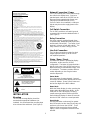
This symbol indicates that dangerous
voltage constituting a risk of electric
shock is present within this unit.
This symbol indicates that there are
important operating and maintenance
instructions in the literature accompanying
this unit.
INSTALLATION
Mounting
The VL550F message display should be
mounted with appropriate hardware (not
included). We recommend the mounting base
to be mounted into wall studs. (See Figure 2)
Network Connection / Power
The RJ45 Ethernet port is accessible through
the cutout in the display base. Connect a
standard patch cable to the VL550F from an
Ethernet switch supporting the Power over
Ethernet specification 802.3at (PoE+).
If a PoE+ switch is not available, a mid-span
injector may be used to supply power to the
display.
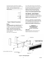
Call Switch Connection
The VL550F provides a call switch input via
screw terminal connections labeled Switch 1.
(See Figure 1)
Relay Connection
One relay output is provided through three
screw terminals, labeled Normally Open (NO)
and Normally Closed (NC). The center screw
terminal is common to both NO and NC. The
relay contacts are rated 1 amp @ 24 Vdc.
Line Out Connection
The Line Out connection provides line level
output sufficient to drive up to 40 Valcom
self-amplified speakers.
Status / Demo / Reset
A multifunction button is provided to display
information, and/or reset the VL550F
configuration. The button is located behind a
pinhole in the case of the VL550F and can be
depressed using a small diameter object, such
as a toothpick. The button provides different
results depending on how long the button
remains depressed.
Status Mode
Press the button for approximately 1 second
and release and the Status display will show the
current IP Address, Power Source status and
the last four digits of the MAC address.
Demo Mode
While the Status display is active, pressing the
button again will enable Demo Mode. In this
mode, the VL550F will display a scrolling
sample message and the flashers will flash.
Demo Mode will display for about 30 seconds
then the VL550F returns to normal operation.
Reset Modes
Pressing the button continuously for greater
than 10 seconds, but less than 20 seconds, will
perform a soft reset on the VL550F. The IP
address will be reset to the factory default
setting. Other configuration items will not be
affected.
IMPORTANT SAFETY INFORMATION
CONSIGNES DE SÉCURITÉ IMPORTANTES
1. Read these instructions.
Lisez ces instructions.
2. Keep these instructions.
Conservez ces instructions.
3. Heed all warnings.
Respectez tous les avertissements.
4. Follow all instructions.
Suivez toutes les instructions.
5. Do not use this apparatus near water.
Ne pas utiliser cet appareil près de l'eau.
6. Clean only with dry cloth.
Nettoyer avec un chiffon sec.
7. Do not block any ventilation openings. Install in accordance with the manufacturer’s
instructions.
Ne pas bloquer les ouvertures de ventilation. Installer formément aux instructions du
fabricant.
8. Do not install near any heat sources such as radiators, heat registers, stoves or other
apparatus (including amplifiers) that produce heat.
Ne pas installer à proximité de sources de chaleur telles que radiateurs, registres de
chaleur, poêles ou autres appareils (y compris les amplificateurs) produisant de la chaleur.
9. Do not defeat the safety purpose of the polarized or grounding-type plug. A polarized plug
has two blades with one wider than the other. A grounding type plug has two blades and a
third grounding prong. The wide blade and the third prong are provided for your safety. If
the provided plug does not fit into your outlet consult an electrician for replacement of the
obsolete outlet.
Ne pas contourner le dispositif de sécurité de la fiche polarisée ou de mise à la terre. Une
fiche polarisée possède deux lames dont une plus large que l'autre. Une fiche de terre a
deux lames et une troisième broche de mise à la terre. La lame large et la troisième
broche sont fournies pour votre sécurité. Si la fiche fournie ne rentre pas dans votre prise,
veuillez consulter un électricien pour le remplacement de la prise obsolète.
10.Protect the power cord from being walked on or pinched particularly at plugs, convenience
receptacles and the point where they exit from the apparatus.
11.Only use attachments/accessories specified by the manufacturer.
N'utilisez que des fixations / accessoires spécifiés par le fabricant.
12. Use only with the cart, stand, tripod, bracket or table specified
by the manufacturer or sold with the apparatus. When a cart is
used, use caution when moving the cart/apparatus combination
to avoid injury from tip-over.
Utilisez uniquement avec le chariot, stand, trépied, support ou table spécifié par le
fabricant ou vendu avec l'appareil. Quand un chariot est utilisé, Soyez prudent lorsque
vous déplacez l'ensemble chariot / appareil pour éviter des blessures dues au
renversement.
13. Unplug this apparatus during lightning storms or when unused for a long period of time.
Débranchez cet appareil pendant les orages ou lorsqu'il n'est pas utilisé pendant une
longue période de temps.
14. Refer all servicing to qualified service personnel. Servicing is required when the
apparatus has been damaged in any way. Such as when the power supply cord or plug is
damaged, liquid has been spilled, objects have fallen into the apparatus or the
apparatus has been exposed to rain or moisture and does not operate normally or has
been dropped.
Confiez toute réparation à un personnel qualifié. Une réparation est nécessaire lorsque
l'appareil a été endommagé de quelque façon. Par exemple lorsque le cordon
d'alimentation ou la fiche est endommagé, du liquide a été renversé, si des objets sont
tombés dans l'appareil ou le appareil a été exposé à la pluie ou à l'humidité et ne
fonctionne pas normalement ou s'il est tombé.

3 947592
Pressing the button continuously for greater
than 20 seconds will perform a hard reset on the
VL550F. All of the configuration items
(including the password) will be reset to factory
default settings.
Figure 1. Network Connections
Setup
Information specific to your application will need
to be programmed into the VL550F using a
computer. The PC used for the programming
should be connected to the same subnet as the
display. Setup will be done using the IP
Solutions Setup Tool. Download the latest
version of the free IP Solution Setup Tool from
Valcom website at
www.valcom.com/vipsetuptool.
The VL550F audio output can be generated
from any Valcom IP Paging source, such as the
VIP-201A SIP Paging Server or a VIP-811A
Network Station Port. Message displays are
programmed and delivered by a Valcom
Engineered Solutions VE6025 Application
Server. Contact Valcom Engineered Solutions
for details on the VE6025 Application Server.
TECHNICAL ASSISTANCE
Assistance is available from the factory when
problems are encountered. Call (540) 563-2000
and press 1 for Technical Support or visit our
website at http://www.valcom.com.
Valcom, Inc. equipment is not field repairable.
Valcom maintains service facilities in Roanoke,
VA. Should repairs be necessary, attach a tag
to the unit clearly stating company name,
address, phone number, contact person, and
the nature of the problem. Send the unit to:
Valcom, Inc.
Repair and Return Dept.
5614 Hollins Road
Roanoke, VA 24019-5056
WARRANTY
Warranty information may be found on our
website at www.valcom.com/warranty.
Figure 2. Mounting Diagram
-
 1
1
-
 2
2
-
 3
3


Valcom VL550F Guide d'installation
- Catégorie
- Commutateurs réseau
- Taper
- Guide d'installation
Documents connexes
Autres documents
-
Luminex GigaCore 26i with PoE Manuel utilisateur
-
Elan gSC2 Mode d'emploi
-
Yamaha SWR2311P-10G Le manuel du propriétaire
-
VTech Eris Terminal VSP715A Manuel utilisateur
-
Dell W-Series 277 Access Points Le manuel du propriétaire
-
Aruba AP-303H Guide d'installation
-
Aruba AP-303H Series Guide d'installation