Luminex GigaCore 26i with PoE Manuel utilisateur
- Catégorie
- Équipement musical supplémentaire
- Taper
- Manuel utilisateur

Gigabit Managed AV Ethernet Switch
GigaCore 26i
GigaCore 26i with PoE
User Manual
V2.4.0
Rev 2
English

Safety instructions
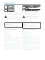
The lightning ash with arrowhead symbol, within an equilateral
triangle, is intended to alert the user to the presence of uninsulated
“dangerous voltage” within the product’s enclosure that may be
of sucient magnitude to constitute a risk of electric shock to
persons.
L’éclair avec une èche à l’intérieur d’un triangle équilatéral est
destiné à attirer l’attention de l’utilisateur sur la présence d’une
« tension dangereuse » non isolée à l’intérieur de l’appareil,
pouvant être susamment élevée pour constituer un risque
d’électrocution.
The exclamation point within an equilateral triangle is intended
to alert the user to the presence of important operating and
maintenance (servicing) instructions in the literature accompanying
the appliance.
Le point d’exclamation à l’intérieur d’un triangle équilatéral
est destiné à attirer l’attention de l’utilisateur sur la présence
d’instructions importantes sur l’emploi ou la maintenance
(réparation) de l’appareil dans la documentation fournie.
CAUTION
TO REDUCE THE RISK OF FIRE OR ELECTRIC SHOCK, DO NOT EXPOSE THIS
APPARATUS TO RAIN OR MOISTURE.
AVERTISSEMENT
POUR RÉDUIRE LES RISQUES D’INCENDIE OU DE DÉCHARGE ÉLECTRIQUE,
N’EXPOSEZ PAS CET APPAREIL À LA PLUIE OU À L’HUMIDITÉ.
CAUTION
NO USER SERVICEABLE PARTS INSIDE. REFER SERVICING TO QUALIFIED SERVICE
PERSONEL.
AVERTISSEMENT
AUCUNE PIÈCE CONTENUE A L’INTÉRIEUR NE PEUT ETRE RÉPARÉE PAR
L’UTILISATEUR, VEUILLEZ CONFIER TOUTE RÉPARATION À UN PERSONNEL
QUALIFIÉ.
■ Read these instructions.
■ Keep these instructions.
■ Heed all warnings.
■ Follow all instructions.
■ Do not use this apparatus near water.
■ Clean only with dry cloth.
■ Do not block any ventilation openings. Install in accordance with the
manufacturer’s instructions.
■ Do not install near any heat sources such as radiators, heat registers, stoves,
or other apparatus (including ampliers) that produce heat.
■ Protect the power cord from being walked on or pinched particularly
at plugs, convenience receptacles, and the point where they exit from the
apparatus.
■ Only use attachments/accessories specied by the manufacturer.
■ Unplug this apparatus during lightning storms or when unused for long
periods of time.
■ Refer all servicing to qualied service personnel. Servicing is required
when the apparatus has been damaged in any way, such as power-supply
cord or plug is damaged, liquid has been spilled or objects have fallen into
the apparatus, the apparatus has been exposed to rain or moisture, does not
operate normally, or has been dropped.
■ Lire ces instructions.
■ Conserver ces instructions.
■ Tenir compte de tous les avertissements.
■ Suivre toutes les instructions.
■ Ne pas utiliser ce produit à proximité d’eau.
■ Nettoyer uniquement avec un chion propre et sec.
■ Ne pas bloquer les orices de ventilation. Installer l’appareil conformément
aux instructions du fabricant.
■ Ne pas installer l’appareil à proximité d’une source de chaleur comme un
radiateur, une bouche de chaleur, un poêle ou tout autre appareil (y compris
un amplicateur) produisant de la chaleur.
■ Acheminer les cordons d’alimentation de sorte qu’ils ne soient pas piétinés
ni coincés, en faisant tout spécialement attention aux ches, prises de courant
et au point de sortie de l’appareil.
■ Utiliser exclusivement les xations et accessoires spéciés par le fabricant.
■ Débrancher l’appareil en cas d’orage ou lorsqu’il doit rester hors service
pendant une période prolongée.
■ Coner toute réparation à un personnel qualié. Faire réparer l’appareil s’il
a subi tout dommage, par exemple si la che ou le cordon d’alimentation est
endommagé, si du liquide a coulé ou des objets sont tombés à l’intérieur de
l’appareil, si l’appareil a été exposé à la pluie ou à de l’humidité, si l’appareil ne
fonctionne pas normalement ou est tombé.
IMPORTANT SAFETY INSTRUCTIONS PRÉCAUTIONS CONCERNANT LA SÉCURITÉ

WARNING: Avoid electric shock and re hazard! Do not defeat
the safety purpose of the polarized or grounding-type plug. A
polarized plug has two blades with one wider than the other.
A grounding type plug has two blades and a third grounding
prong. The wide blade or the third prong are provided for
your safety. If the provided plug does not t into your outlet,
consult an electrician for replacement of the obsolete outlet.
AVERTISSEMENT: Evitez les décharges éléctriques et les risques
d’incendie.
Ne pas modier le système de sécurité de la che polarisée ou
de la che de terre. Une che polarisée dispose de deux broches
dont une est plus large que l’autre. Une che de terre dispose de
deux broches et d’une troisième pour le raccordement à la terre.
Cette broche plus large ou cette troisième broche est destinée
à assurer la sécurité de l’utilisateur. Si la che équipant l’appareil
n’est pas compatible avec les prises de courant disponibles, faire
remplacer les prises par un électricien.
THIS APPARATUS MUST BE EARTHED CET APPAREIL DOIT ÊTRE RELIÉ À LA TERRE
THIS APPARATUS MUST BE EARTHED
SWEDEN: Apparaten skall anslutas till jordat uttag
NORWAY: Apparatet må tilkoples jordet stikkontakt
FINLAND: Laite on liitettävä suojamaadoituskoskettimilla varustettuun pistorasiaan
DENMARK: Apparatets stikprop skal tilsluttes en stikkontakt med jord, som giver forbindelse til stikproppens jord
CAUTION: DOUBLE POLE/NEUTRAL FUSING ATTENTION: FUSIBLE NEUTRE BIPOLAIRE
VENTILATION OPENINGS:
The system heat vents located on each side dissipate heat. Do not block these openings. Leave at least 5 inches of space at the rear and 2 inches of space at the
sides of the switch for proper ventilation. Be reminded that without proper heat dissipation and air circulation, system components might overheat, which could
lead to system failure or even severely damage components.
WARNING: To prevent the Gigacore26i (with PoE) from overheating, do not operate it in an area that exceeds the maximum recommended ambient temperature
of 50°C for the Gigacore 26i and 40°C for the Gigacore 26i with PoE.
POWER CABLE:
Use only approved power cables. If you have not been provided with a power cable for your system or for any AC powered option intended for your system,
purchase a power cable that is approved for use in your country. The power cable must be rated for the product and for the voltage and current marked on the
product’s electrical ratings label. The voltage and current rating of the cable should be greater than the ratings marked on the product.
DISCONNECT DEVICE:
The plug- IEC socket combination must be accessible at all times, because it serves as the main disconnecting device.
SAFETY CLASSIFICATION OF TRAFFIC PORTS
■ Serial port has a safety status of EARTHED SELV
■ 10/100/1000BaseT ports have a safety status of UNEARTHED SELV.
SAFETY CLASSIFICATION OF POWER INPUTS
■ Backup power port:
12V connections have a safety status of EARTHED SELV
-54V connections have a safety status of UNEARTHED SELV
■ Mains Input – IEC connection has a safety status of PRIMARY CIRCUIT.

4
Compliance information
FCC Compliance Statement
This device complies with Part 15 of the FCC Rules. Operation is subject to the following two condiftions:
(1) this device may not cause harmful interference, and
(2) this device must accept any interference received; including interference that may cause undesired operation.
■ IMPORTANT NOTICE: DO NOT MODIFY THIS UNIT!
This product, when installed as indicated in the instructions contained in this manual, meets FCC requirements. Modications not expressly approved by
Luminex Lighting Control Equipment nv may void your authority, granted by the FCC, to use the product.
■ This Equipment has been tested and found to comply with the limits for a Class A digital device, pursuant to Part 15 of the FCC rules. These limits are
designed to provide reasonable protection against harmful interference when the equipment is operated in a commercial environment. This equipment
generates, uses and can radiate radio frequency energy and, if not installed and used in accordance with the instructions, may cause harmful interference to
radio communications. Operation of this equipment in a residential area is likely to cause harmful interference in which case the user will be required to correct
the interference at his own expense.
Industry Canada Compliance Statement
This Class A digital apparatus complies with Canadian ICES-003.
Cet appareil numérique de la classe A est conforme à la norme NMB-003 du Canada.
European Community Compliance Statement
Disposal of Waste Equipment by users in the European Union
Information for Users on Collection and Disposal of Old Equipment
This symbol on the products, packaging, and/or accompanying documents means that used electrical and electronic products should not be mixed
with general household waste.
For proper treatment, recovery and recycling of old products, please take them to applicable
collection points, in accordance with your national legislation and the Directives 2002/96/EC.
By disposing of these products correctly, you will help to save valuable resources and prevent any potential negative eects on human health and
the environment which could otherwise arise from inappropriate waste handling.
For more information about collection and recycling of old products, please contact your local municipality, your waste disposal service or the point
of sale where you purchased the items.
[For business users in the European Union]
If you wish to discard electrical and electronic equipment, please contact your dealer or supplier for further information.
[Information on Disposal in other Countries outside the European Union]
This symbol is only valid in the European Union. If you wish to discard these items, please contact your local authorities or dealer and ask for the
correct method of disposal.
This is a class A product. In a domestic environment this product may cause radio interference in which case the user may be required to take
adequate measures.

5
Warranty information
Unless otherwise stated, your product is covered by a two (2) years parts and labor limited warranty. It is the owner’s
responsibility to furnish receipts or invoices for verication of purchase, date, and dealer or distributor. If purchase date
cannot be provided, date of manufacture will be used to determine warranty period.
Any Product unit or parts returned to Luminex LCE must be packaged in a suitable manner to ensure the protection
of such product unit or parts, and such package shall be clearly and prominently marked to indicate that the package
contains returned product units or parts. Accompany all returned product units or parts with a written explanation of
the alleged problem or malfunction.
Registration
Use your favorite web browser, and visit http://www.luminex.be/support.php?show=registration
to register your product online.
By registering, you become eligible to receive the following:
■ Technical support information
■ Software update and upgrade notices
■ Hardware warranty information
All shipping will be paid by the purchaser. Items under warranty shall have return shipping paid by the manufacturer
only in the European Union.
Under no circumstances will freight collect shipments be accepted. Prepaid shipping does not include rush expediting
such as air freight. Air freight can be sent customer collect in the European Union.
Warranty is void if the product is misused, damaged, modied in any way, or for unauthorized repairs or parts.
In the box
1 x LU 01 00052 GigaCore 26i with PoE26i or 1 x LU 01 00052-POE GigaCore 26i with PoE
1 x Quick Start Guide
1 x Safety instructions.
Limited warranty
Returning under warranty
Freight

Table of Content
■ Safety instructions 2
■ Compliance information 4
■ Warranty information 5
■ Limited warranty 5
■ Returning under warranty 5
■ Freight 5
■ Registration 5
■ In the box 5
■ Description 8
■ Front panel 8
■ Rear panel 8
■ LED indicators 9
■ Installing Mini GBIC (SFP) transceivers 9
■ Connecting the Redundant Power Supply Unit 10
■ GigaCore features explained 11
■ RLink X 11
■ Groups 12
■ MultiLinkX 13
■ Starting 15
■ Connection to the web interface 15
■ Status Page 16
■ Global Page 17
■ RLinkX 21
■ Groups 22
■ MultiLinkX 23
■ PoE 25
■ Prole Manager 27
■ Reset the unit 30
■ Reset 30
■ Reload Default 31
■ Factory Reset 31
■ Specications 32
■ Additional documentation 34

7
This page is intentionally left blank

8
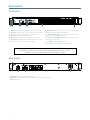
Description
NOTE : PORT 21 TO 24 ARE DUAL MEDIA PORTS.
RJ45 PORTS 21 TO 24 CAN’T BE USED AT THE SAME TIME AS SFP PORTS 21 TO 24.
SFP PORTS 21 TO 24 HAVE PRIORITY OVER RJ45 PORTS 21 TO 24.
12 3 5 74 6 8 9
10
1 - OK LED: Indicates the general status of the switch
2 - PoE LED: Indicates the status of the PoE functionality
and the PoE supplies (GigaCore 26i with PoE only)
3 - RLinkX: Indicates the RLinkX status
4 - Power: Indicates the status of the power supplies
5 - Mode LED: Indicates the selected state for the port’s
Mode LEDs (see “LED indicators” on page 9)
6 - Mode button: Use this button to browse through the
dierent states for the Port Mode LEDs
7 - 26 x Port Mode LED: According to the selected state,
the LED will show dierent colours
8 - 26 x Port Link/Speed LED: Shows the current speed
and link activity of a port
9 - 24 x RJ45 10/100/1000Mbps port
10 - 6 x SFP cage for Mini-GBIC transceiver
1 2
3
1 Serial port: RS232 console port on RJ45
2 RPSU port: Connect here the optional Redundant Power Supply Unit
3 Power: IEC inlet
Front panel
Rear panel

9
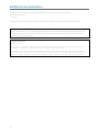
Switch LED Colour Description
OK (General status LED) Green All OK
Green blink Unit is writing to the ash. Do not disconnect power
Orange Temperature warning
Red blink Temperature or Fan error
Red/Green blink The unit is ashing new rmware. Do not disconnect power
PoE LED (GigaCore 26i with PoE only) Green Internal PoE supply OK and RPSU connected. PoE functionality OK
Orange Internal PoE supply OK (no RPSU connected) - PoE functionality OK
Red blink PoE supply or PoE functionality error
RLinkX LED Green RLinkX is active
Power LED Green Internal Power supply OK and RPSU connected
Orange Internal power supply OK (no RPSU connected)
Red blink Power error
State Mode LED Port Mode LED Description
Groups White Group colour The LED colour indicates the group assignation of the port
RLinkX Blue Blue Indicates a redundant port
MultiLinkX Magenta Magenta
White
MultiLinkX is enabled on this port
MultiLinkX is active on this port
PoE Yellow Yellow PoE is activated on this port
Orange Port is sourcing a device
Red Error on PoE
Dark Mode O O All port’s LEDs are switched o. Switch’s status LEDs remain
available. Ideal to reduce light emmited by the switch
Port LED Status Description
Link O No link
Green Gigabit connection
Orange 10/100 Mbps connection
Blink Activity
The LED indicators of the GigaCore 26i and 26i (with PoE) show General, PoE, RLinkX, Power and Link/Speed statuses.
The LED indicators of the GigaCore 26i
GigaCore 26i with PoE26i are meant to provide the user a maximum of information. Thanks to the mode button, the user
can get all necessary information at a glance. Simply press the mode button to browse through the dierent states.
Installing Mini GBIC (SFP) transceivers
The GigaCore 26i (with PoE) comes with six SFP cages at the front of the unit. These cages accept mini GBIC transceivers.
In order to get best the performances, Luminex recommends the use of the following transceivers:
LU 90 00871 GigaCore 1.25Gd Multi-Mode ber transceiver
LU 90 00872 GigaCore 1.25Gd Single Mode ber transceiver
LU 90 00874 GigaCore 1.25Gd copper RJ45 transceiver
Recommended transceivers
LED indicators

10
Connect the power cable to the device, and connect the other side of the cable to the mains. It will take approximately
20 seconds for the switch to boot up. You’ll then be able to use it.
THIS UNIT HAS MORE THAN ONE POWER SUPPLY. DISCONNECT ALL POWER SUPPLIES BEFORE
SERVICING TO AVOID ELECTRIC SHOCK.
Connecting the Redundant Power Supply Unit
The GigaCore 26i (with PoE) provides a connector to an optional Luminex Redundant Power Supply Unit, providing
redundancy on power level for both the mains as the PoE power.
Attach only the following RPSU to the RPSU connector: LU 01 00061 GigaCore RPSU MKII

11
GigaCore features explained
The GigaCore range of switches oers a bunch of unique features which greatly simplify your everyday job.
These features will be explained in the following pages :
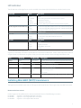
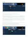
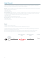
To create redundant paths with RLinkX, simply connect a minimum of two links between to GigaCore switches. The blue
RLinkX LEDs of the connected ports will turn on, indicating the redundancy is active and available.
If you port’s RLinkX LED turns o, this means you lost one of your redundant path.
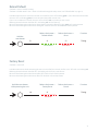
RLinkX, which stands for Redundant Link by LumineX, is an automated system to easily create redundant paths between
your GigaCore switches. Switches automatically create active and backup paths, providing an eortless methode to
create safe networks.
If one of the active paths fails, the switches will enable a backup path, in a seamless manner.
By default, all GigaCore ports have RLinkX enabled, which means you can interconnect any GigaCore switch between
each other. All redundant paths will be created automatically by the switches, no need for conguration.
Active path
Backup path
RlinkX
RlinkX
RlinkX
Active link Backup link
Step 1
User connect two
switches with two links.
The switches
automatically create a
backup link.
Faulty link Backup link
20 to 40ms
Step 2
Active link becomes
unavailable (cable or
bre issue)
Faulty link Active link
Step 3
Backup link becomes
active automatically
RLinkX

12
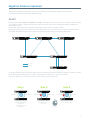
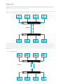
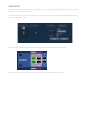
Groups function allows the user to segment the network into several subnets. The main benet of this function is that no
subnet will aect the other ones, on protocol level.
The user can create several groups on the network, and each device included in a group will be able to communicate
with devices of this group only. This will result in a better bandwidth , and no protocol conict.
Video over IP OUT
Video over IP INSound Over IP Console
Sound Over IP processor
Light Over IP Console
Light Over IP Converter
Inter Switch Links
(ISL)
Three groups have been created in the above illustration: Red, Green and Blue groups. Each device included in each
group can communicate with devices from the same group. Thus, the sound console and the sound processor can talk
to each other, without being ooded by packets streamed by the two other groups.
The GigaCore switches oer 20 groups, to which the user can assign any of the ports. Two devices must be part of the
same group to communicate.
When more than one switch is used in a group based network, the Inter Switch Link group (ISL Group 0) must be used to
forward the group’s packets between switches.
Groups

13
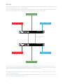
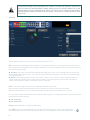
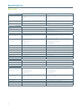
Most of the time, a redundant link set with RLinkX between two GigaCore switches will t for every day event. A
1000Mbps link is more than enough for most of the current applications. However, it can happen that you’ll need to
transfer a larger amount of data between the switches.
Below is an example where four video transmitters will needs to transmit four streams to each dedicated receiver. Each
stream requires a throughput of 400Mbps, which represents 1600Mbps in total.
Tx:
400Mbps
Tx:
400Mbps
Tx:
400Mbps
Tx:
400Mbps
Rx:
400Mbps
Rx:
400Mbps
Rx:
400Mbps
Rx:
400Mbps
1000Mbps
However, one link only is active between the switches, as the other link is used in case of link failure. So a maximum
of 1000Mbps data transfer can be achieved on this link. In the above example, we need 1600Mbps of throughput to
transfer all four video streams between the switches. This is not enough, the link between the switches will create a
bottleneck, resulting in data loss or data delay. The video streams won’t be delivered in time., and will create lag in the
video output.
The solution? MultiLinkX !
Tx:
400Mbps
Tx:
400Mbps
Tx:
400Mbps
Tx:
400Mbps
Rx:
400Mbps
Rx:
400Mbps
Rx:
400Mbps
Rx:
400Mbps
1000Mbps
MultiLinkX

14
MultiLinkX enables you to gather several links together, and turn them into one virtual link. This provides you with more
bandwidth available between the switches, and thus more throughput. MultiLinkX can accept as many ports as you
want into an aggregation, and up to 8 aggregations can be created on a switch.
Working with PtP
When working with PtP (Precision Time Protocol), you’ll notice an inverted PTP icon to indicates the PTP enabled port in
an aggregation. You must always link the lowest ports of the active aggregation to each other to avoid problems with
PTP. Best is to never create a cross link between ports in a dierent order.
1+1 is not 2 !
By adding an additional link into the aggregation, we can easily think we’ll have the addition of all bandwidth available
per cable.
However, MultiLinkX relies on LACP (Link Aggregation Control Protocol). The algorythm used by the protocol requires
several parameters of the Ethernet frame to decide to which port of the aggregation the frame will be forwarded to.
The protocol uses the following parameters:
Source Mac Address
Source IP Address
Source Port (TCP/UDP)
Destinatation IP address
Destination Port (TCP/UDP)
The ports included in the aggregation
In some circumstances, it might happen that several data streams will be forwarded to the same port. To know where
the data stream will be forwarded to, you can have a look at our aggregation planning web page.
Simply type the following link into the address bar of your favorite web browser:
http://IPOFMYSWITCH/aggregation_code.html
According to the parameters of your Ethernet frame, the page will show you wich port will be in use. This allows you to
predict, but also to solve some problems. In the unlikely event of an overloaded link in an aggregation, user can solve the
problem simply by changing the appropriate IP address for the source for instance.
MultiLinkX technology is available on the ISL ports only !
It is also a good habit to allocate the specic number of link in an aggregation to fulll your throughput
requirement, plus one link. If one link fails, you’ll still have the minimum number of necessary link to tranfer all
your data !

15
Every GigaCore switch embeds a built-in web server, which excludes the need of a dedicated application to congure
the unit. Browsers such as Chrome, Internet Explorer (IE 9 minimum), Firefox or Safari can be used to reach the web
server.
Every unit comes with a default IP address, visible at the rear of the unit. Set your computer with an IP address within the
same subnet (do not use the same IP address!)
■ Example 1: Switch IP address: 192.168.1.1, Netmask: 255.255.255.0
Computer IP address: 192.168.1.2, Netmask 255.255.255.0
■ Example 2: Switch IP address: 192.168.2.112, Netmask: 255.255.0.0
Computer IP address: 192.168.2.113, Netmask 255.255.0.0
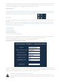
Connect your computer to the switch with a Cat5E network cable at least, and launch your favorite web browser. Type
the IP address of the switch in the address eld, and press enter. You’ll be prompted to enter a login:
Use admin in the login eld, and leave the password led blank. You reach the status page of the GigaCore switch.
Starting
The device operates with an AC voltage between 100V and 240VAC within a frequency range of 50Hz to 60Hz.
An IEC socket is located at the rear of the unit. Please use an IEC plug compliant cable to feed power to the unit.
Luminex recommends the use of a power cable, tted with a locking mechanism to ensure a reliable connection to the
device.
Connection to the web interface

16
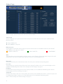
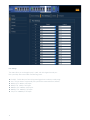
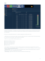
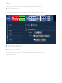
Main menu :
On the left hand side, you can nd the main menu. Click on any tab to reach the corresponding menu.
Port status :
This table gives you a quick overview of the switch’s ports settings. Parameters such as port speed and legend can be
modied in the following menu: Global > Port Settings (see “Port settings” on page 18)
IP Settings :
Find here all the network settings of the switch. These parameters can be modied in the following menu: Global >
Device Settings (see “Device setttings” on page 17)
System Info :
Find here all the device’s info such as serial number, device name, system identier, MAC address, system description, and
if a conguration prole is currently in use. These information can be modied in the following menu:
Global > Device Settings (see “Device setttings” on page 17)
Switch image :
The top image gives you a quick overview of the switch port status (front and rear). Actives ports are lled with the
following colours:
■ Orange: 100Mbps link
■ Green: 1000Mbps (1Gbps) link
The status page is split into several panes that will be described below:
Status Page
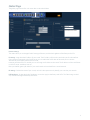
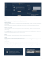
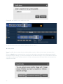
Wink:
The feature allows you to easily identify a GigaCore switch in a stack of device. Click on the Luminex Logo on the switch
image, all four status LEDs on the left hand side of the switch will start blinking three times.
RPSU connectors:
On the right hand side of the switch’s image, two squares indicates the status of the RPSU connectors (PSU and PoE).
Three dierents status colors are available:
NO RPSU CONNECTED
RPSU CONNECTED
POWER ERROR

17
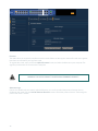
Global Page
Device setttings
This menu allows you to change IP and ID settings of the unit, and also the brightness of the front panel’s LEDs.
IP settings: Assign here the IP address of your switch. This IP address will be used to reach the switch’s web interface.
If your network is equipped with a DHCP server, you can enable the DHCP client of the switch, for it to receive
automatically an IP address from the DHCP server.
However, mind that if DHCP is enable, you can still assign an IP address to the switch. This IP address will be used if there
is no DHCP server available at boot up.
Enter your default gateway IP address if your switch needs to be reached from a routed network.
ID settings: Set here the name of your switch, and add a description to easily identify your switch in your network.
LED Brightness: Set here the level of brightness you wish to apply to the front panel’s LEDs. This fader brings an ideal
way to reduce the light emmited by the switch.
The global page contains four sub menus that are described below:

18
Port settings
This menu allows you to change the port’s speed, and add a legend to each port.
Port speed drop down menu oers the folowing speed :
■ Disabled : Disable the port. Port will appeared grayed out on the top switch image
■ Auto : The port detects automatically the speed of the connected device (default)
■ 10Mbps HDX : 10Mbps Half Duplex
■ 10Mbps FDX : 10Mbps Full Duplex
■ 100Mbps HDX : 100Mbps Half Duplex
■ 100Mbps FDX : 100Mbps Full Duplex
■ 1Gbps FDX : 1000Mbps Full Duplex

19
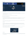
Utilities
This page brings you the tool to reset your unit in dierent ways, and to set some default security parameters.
Reset
This menu allows the user to bring the switch into dierent levels of reset.
Preserve IP settings
Tick the upper check box if you wish to bring the unit back to the default settings, and keep the actual IP parameters set
on the switch.
If you leave this checkbox unticked, the unit’s IP address will be set back as the one printed at the back of the unit.
Preserve all user proles
Tick the lower check box if you wish to bring the unit back to the default settings, and keep the proles stored in the
prole manager.
Press the Apply Reset button once you’ve selected the appropriate options for your reset. Reset the units with the two
unticked checkboxes will bring the unit back to its factory settings.
Reboot
Press the “Reboot Now” button to reboot the unit. All your parameters will be preserved
Security
User can set here a password to protect the web interface’s access.
Default login of the web interface is admin, there is no default password. Click on Change Password to apply your new
settings.
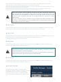
Default Prole
By clicking on the checkbox, the user can protect the prole stored in slot 1 from being deleted or overwritten.
When the user performes a Reload Default from the front panel’s mode button (see “Reload Default” on page 31), the
unit will be reloaded with prole 1. This makes a handy tool to easily recall your favorite prole.
Once the rst prole is protected and set as default prole, a lock will appear on the prole’s tab.
Locked Prole

20
Firmware
This menu allows you to upload a new rmware to the switch. Please visit the support section of our web site to get the
latest rmware available for your GigaCore switch.
To upgrade the switch, simply click on the Upload Firmware button, and select the rmware on your computer. The
upgrade procedure takes about 4 minutes to complete.
Alternate image
If you’re not satised with your recently uploaded rmware, you can always reload the previous rmware that was
installed on the switch. Press the Activate alternate rmware button to reload the previous rmware. The downgrade
process takes about 1 minute.
!! WARNING : DO NOT DISCONNECT POWER DURING FIRMWARE UPGRADE !!
La page est en cours de chargement...
La page est en cours de chargement...
La page est en cours de chargement...
La page est en cours de chargement...
La page est en cours de chargement...
La page est en cours de chargement...
La page est en cours de chargement...
La page est en cours de chargement...
La page est en cours de chargement...
La page est en cours de chargement...
La page est en cours de chargement...
La page est en cours de chargement...
La page est en cours de chargement...
La page est en cours de chargement...
La page est en cours de chargement...
La page est en cours de chargement...
-
 1
1
-
 2
2
-
 3
3
-
 4
4
-
 5
5
-
 6
6
-
 7
7
-
 8
8
-
 9
9
-
 10
10
-
 11
11
-
 12
12
-
 13
13
-
 14
14
-
 15
15
-
 16
16
-
 17
17
-
 18
18
-
 19
19
-
 20
20
-
 21
21
-
 22
22
-
 23
23
-
 24
24
-
 25
25
-
 26
26
-
 27
27
-
 28
28
-
 29
29
-
 30
30
-
 31
31
-
 32
32
-
 33
33
-
 34
34
-
 35
35
-
 36
36


Luminex GigaCore 26i with PoE Manuel utilisateur
- Catégorie
- Équipement musical supplémentaire
- Taper
- Manuel utilisateur
dans d''autres langues
Autres documents
-
D-Link DES-1316 Guide d'installation
-
Uniden UCSWITCH9 Le manuel du propriétaire
-
Grandstream GWN780x(P) L2+ Guide d'installation
-
Valcom VL550F Guide d'installation
-
-
SMC Networks 8150L2 Manuel utilisateur
-
red lion NT24k Series Manuel utilisateur
-
Foundry Networks FES12GCF Guide d'installation
-
 ANTAIRA LMX-0702G-SFP-V2 Series Manuel utilisateur
-
