Thermo Scientific Finnpipette F1 Mode d'emploi
- Taper
- Mode d'emploi

1
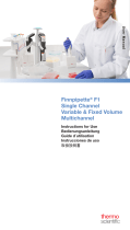
Finnpipette® F1
Single Channel
Variable & Fixed Volume
Multichannel
Instructions for Use
Bedienungsanleitung
Guide d´utilisation
Instrucciones de uso
取扱説明書
User Manual

2
This product complies with the European Union Directive 98/79/EC, and it is marked with
a CE-marking.
When the product is used in applications related to the directive 98/79/EC, read the
additional information at www.thermofi sher.com or contact the manufacturer at info.
pipettes@thermofi sher.com to ensure correct and safe use.
The CE-mark covers the system containing the CE-marked Finnpipette F1 pipette and the
CE-marked Finntips.
Product specifi cations are subject to change without prior notice. Finnpipette® and Finntip®
are registered trademarks of Thermo Fisher Scientifi c Oy.
Ce produit est conforme à la directive de l’Union européenne 98/79/CE et porte le
marquage CE.
Lorsque le produit est utilisé pour des applications relatives à la directive 98/79/EC, veuillez
prendre connaissance des informations complémentaires à www.thermofi sher.com ou
contacter le constructeur à info.pipettes@thermofi sher.com. Ceci pour garantir un usage
adéquat et sûr.
Le marquage CE s’applique au système comprenant la Finnpipette F1 et les cônes Finntip.
Les spécifi cations du produit sont sujettes à modifi cation sans avis préalable. Finnpipette®
et Finntip® sont des marques déposées de Thermo Fisher Scientifi c Oy.
Este producto cumple la Directiva de la Unión Europea 98/79/CE y presenta el marcado CE.
Cuando el producto sea usado en aplicaciones afectadas por la directiva 98/79/EC, por favor,
lea la información adicional en www.thermofi sher.com o contacte con el fabricante en
info.pipettes@thermofi sher.com para asegurar su uso correcto y seguro.
El marcado CE corresponde al sistema que contiene la pipeta Finnpipette F1 con el marcado
CE y las puntas de pipeta Finntip con marcado CE.
Las especifi caciones del producto pueden cambiar sin previo aviso. Finnpipette® y Finntip®
son marcas registradas de Thermo Fisher Scientifi c Oy.
本製品は欧州指令98/79/ECに準拠しており、CEマーキングが付いています。
製品を指令98/79/ECに関連するアプリケーションで使用するときは、適切で安全に
ご使用いただくため、www.thermofi sher.com に掲載の追加情報をお読みになる
か、製造元info.pipettes@thermofisher.com にお問い合わせください。
CEマークは、CEマークの付いた Finnpipette F1ピペットおよびCEマークの付いた
Finntipピペットチップを含むシステムを対象としています。
製品仕様は事前の予告なく変更されることがあります。フィンピペット®とフィンチ
ップ®は、サーモフィッシャーサイエンティフィックの登録商標です。
Dieses Produkt entspricht der Europäischen Richtlinie 98/79/EG und ist mit dem CE-Symbol
gekennzeichnet.
Sollte das Produkt in Anwendungen verwendet werden, die in Verbindung zur Direktive
98/79/EC stehen, lesen Sie die Zusatzinformationen auf www.thermofi sher.com oder
kontaktieren Sie den Hersteller unter info.pipettes@thermofi sher.com, um die richtige
und sichere Verwendung zu gewährleisten.
Die CE-Kennzeichnung bezieht sich auf die Kombination der Finnpipette F1 mit Finntip-
Pipettenspitzen.
Wir behalten uns das Recht auf unangekündigte Änderungen der Produktspezifi kationen vor.
Finnpipette® und Finntip® sind eingetragene Warenzeichen der Fa. Thermo Fisher Scientifi c Oy.

3
CONTENTS
PRODUCT DESCRIPTION 4
PACKAGE 5
SAFETY 5
PIPETTE OPERATION 6
PIPETTING TECHNIQUES 7
CALIBRATION AND ADJUSTMENT 8
MAINTENANCE 12
TROUBLE SHOOTING 14
SPARE PARTS 63-71
English
INHALT
PRODUKTBESCHREIBUNG 15
PACKUNGSINHALT 16
SICHERHEIT 16
BEDIENUNG DER PIPETTE 17
PIPETTIERMETHODEN 18
KALIBRIERUNG UND JUSTIERUNG 19
WARTUNG 23
FEHLERBEHEBUNG 26
ERSATZTEILE UND ZUBEHÖR 63-71
Deutsch
SOMMAIRE
DESCRIPTION DU PRODUIT 27
CONDITIONNEMENT 28
CONSIGNES DE SÉCURITÉ 28
UTILISATION DE LA PIPETTE 29
MÉTHODES DE PIPETAGE 30
CALIBRAGE 31
ENTRETIEN 35
EN CAS DE PROBLEME 37
PIÈCES DÉTACHÉES 63-71
Français
CONTENIDO
DESCRIPCIÓN DEL PRODUCTO 38
PAQUETE 38
SEGURIDAD 38
USO DE LA PIPETA 40
TÉCNICAS DE PIPETEO 41
CALIBRACIÓN Y AJUSTE 42
MANTENIMIENTO 46
SOLUCIÓN DE PROBLEMAS 49
PIEZAS DE RECAMBIO 63-71
Español
目次
製品について 50
パッケージ 51
安全にお使いいただくために 51
ピペットの操作 52
ピペッティングテクニック 53
キャリブレーション 54
メンテナンス 58
トラブルシューティング 60
保証規定 62
パーツ及び付属品 63-71
日
本
語

4
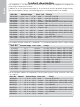
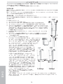
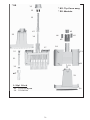
Product description
The Finnpipette F1 is a continuously adjustable, general purpose micropipette for sampling and
dispensing accurate liquid volumes.
It operates on an air displacement principle (i.e. an air interface) and uses detachable, disposable tips.
The adjusted delivery volume is displayed digitally on a readout window in the handle.
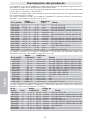
The fourteen different models of Finnpipette F1 pipettes cover a volume range from 0,2 μl to 10 ml.
Order No. Volume Range
Color code
Finntip
4641010N 0,2 μl to 2 μl pink Flex 10, 10, 20, 50
4641020N 0,5 μl to 5 μl pink Flex 10, 10, 20, 50
4641030N 1 μl to 10 μl pink Flex 10, 10, 20, 50
4641040N 1 μl to 10 μl yellow
Flex 200, 250 Univ., 200 Ext, 300, Flex 300
4641050N 2 μl to 20 μl
turquoise
50
4641060N 2 μl to 20 μl yellow
Flex 200, 250 Univ., 200 Ext, 300, Flex 300
4641130N 5 μl to 50 μl
turquoise
50
4641140N 5 μl to 50 μl yellow
Flex 200, 250 Univ., 200 Ext, 300, Flex 300
4641070N 10 μl to 100 μl yellow
Flex 200, 250 Univ., 200 Ext, 300, Flex 300
4641080N 20 μl to 200 μl yellow
Flex 200, 250 Univ., 200 Ext, 300, Flex 300
4641090N 30 μl to 300 μl orange Flex 300, 300
4641100N 100 μl to 1000 μl blue Flex 1000, 1000, 1000 Ext
4641110N 0,5 ml to 5 ml green 5 ml
4641120N 1 ml to 10 ml red 10 ml, Flex 10 ml Ext
The thirteen different models of Finnpipette F1 Fixed Volume pipettes cover a volume range
from 1 μl to 10 ml.
Order No. Volume Range Color code Finntip
4651020N 10 μl dark blue Flex 200, 250 Univ., 200 Ext, 300, Flex 300
4651130N 20 μl dark blue Flex 200, 250 Univ., 200 Ext, 300, Flex 300
4651030N 25 μl dark blue Flex 200, 250 Univ., 200 Ext, 300, Flex 300
4651040N 50 μl dark blue Flex 200, 250 Univ., 200 Ext, 300, Flex 300
4651050N 100 μl dark blue Flex 200, 250 Univ., 200 Ext, 300, Flex 300
4651140N 200 μl dark blue Flex 200, 250 Univ., 200 Ext, 300, Flex 300
4651060N 250 μl dark blue Flex 1000, 1000, 1000 Ext
4651070N 500 μl dark blue Flex 1000, 1000, 1000 Ext
4651080N 1000 μl dark blue Flex 1000, 1000, 1000 Ext
4651090N 2000 μl dark blue 5 ml
4651100N 3000 μl dark blue 5 ml
4651110N 5000 μl dark blue 5 ml
4651120N 10000 μl dark blue 10 ml, Flex 10 ml Ext
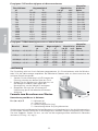
The ten different models of Finnpipette F1 Multichannel pipettes cover a volume range from
1 μl to 300 μl.
Order No. Channel Volume Range Color code Finntip
4661000N 8 1 μl to 10 μl pink Flex 10, 10, 20, 50
4661010N 8 5 μl to 50 μl yellow
Flex 200, 250 Univ., 200 Ext, 300, Flex 300
4661020N 8 10 μl to 100 μl yellow
Flex 200, 250 Univ., 200 Ext, 300, Flex 300
4661030N 8 30 μl to 300 μl orange Flex 300, 300
4661040N 12 1 μl to 10 μl pink Flex 10, 10, 20, 50
4661050N 12 5 μl to 50 μl yellow
Flex 200, 250 Univ., 200 Ext, 300, Flex 300
4661060N 12 10 μl to 100 μl yellow
Flex 200, 250 Univ., 200 Ext, 300, Flex 300
4661070N 12 30 μl to 300 μl orange Flex 300, 300
4661080N 16 1 μl to 10 μl purple 20
4661090N 16 5 μl to 50 μl
turquoise
50
English

5
English
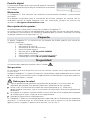
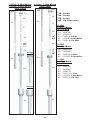
Digital display
The adjusted delivery volume is clearly indicated in the large
digital display on the handle.
Raw materials
The Finnpipette F1 is made of mechanically durable and chemically resistant materials.
For waste disposal instructions, please contact your local environmental agency. For more
information, please contact us at info.pipettes@thermofi sher.com.
Description of tips
Finntips are recommended for use with the Finnpipette F1.
They are made of virgin natural colour polypropylene, generally regarded as the only
contamination free material suitable for tips. Finntips are also autoclavable (121°C).
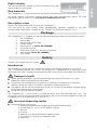
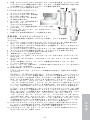
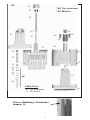
Package
The Finnpipette F1 is shipped in a specially designed package containing the following items:
1. The Finnpipette
2. Service tool
3. Multichannel service tool
4. Finntip sample
5. Bag of grease 1g (Order No. 3300200)
6. Instruction manual
7. Calibration certifi cate / Warranty certifi cate
8. Shelf hanger (Order No. 2206040)
9. Two stickers
Safety
Cautions are marked with this symbol .
Intended use
The intended use of the device is to transfer liquids in the volume range of
0,2 μl to 10 ml.
The F1 Finnpipette pipette and Finntips are designed as a component of an analyzing system
for an end user, who is responsible for validating the system to ensure reliable and safe results.
Damage to health
Follow general procedures for hazard prevention and safety instructions; e.g. wear
protective clothing, eye protection and gloves.
For use and waste disposal of hazardous (e.g. radioactive and potentially infectious)
material, follow the safety instructions and general laboratory practice.
The pipette and tips are not intended for in vivo use. Do not use the pipette for pipetting any
liquid to be injected into a human body.
Do not eject the tip towards anybody.
The Finnpipette F1 is to be used by trained personnel with required laboratory skills. The
instructions for use must be read prior to and during the use of the device (pipette and tip). The
F1 pipette can be used between +4°C and +40°C.
Incorrect dispensing results
Performance may vary due to:
a. pipetting method (forward pipetting technique recommended)
b. temperature (air, liquid, vessel, pipette, and tip)
c. pressure
d. humidity
e. operator, e.g. thumb movement, pipetting angle
f. liquid density, viscosity and vapor pressure
g. type of tip

6
If the pipetting performance is critical to the outcome of a specifi c application, the result has
to be assured with an alternative test, and if this is not an option, by duplicate testing.
The possibility of an incorrect volume delivery during pipetting cannot be entirely mitigated.
To avoid inaccurate dispensing and/or leakage, check that the tip is properly attached to
the pipette.
When rotating the volume adjustment button, do not exceed the volume range of the pipette.
Otherwise the pipette may be damaged or affect pipetting performance.
Pipetting performance cannot be guaranteed if the tip is reused.
Choose only a tip and pipette with matching color coding.
Disposal of the Materials
Follow laboratory and country-specifi c procedures for the disposal of biohazardous or radioactive
waste. Refer to local regulations for the disposal of infectious material.
Warning The tips can be potentially infectious. Dispose of all used disposable tips as
biohazardous waste.
Warning Decontaminate the pipette before disposal.
For waste disposal instructions, contact your local environmental agency. For more information,
please contact us at info.pipettes@thermofi sher.com
Regarding the original packaging and packing materials, use the recycling operators known
to you.
For more information, contact your local Thermo Fisher Scientifi c representative.
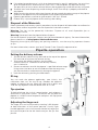
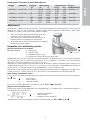
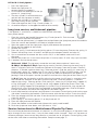
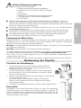
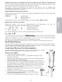
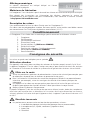
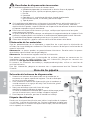
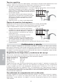
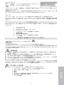
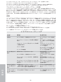
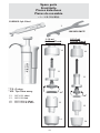
Pipette operation
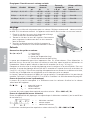
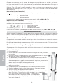
Setting the delivery volume
1. Set the delivery volume using the knob on the top of the pipette.
Pull the knob to activate the volume setting.
2. To increase the delivery volume, turn the knob
counterclockwise. To decrease the delivery volume,
turn it clockwise.
3. Do not set volumes outside the pipette´s specifi ed volume range.
Using excessive force to turn the knob outside the range may
jam the mechanism and eventually damage the pipette.
4. Lock the volume by pushing the knob down.
ID-tag
You can mark the pipette application, your initials, the
calibration date, etc. on the ID-tag. Remove the pipette’s
module to replace the tag. Mark the label with a pencil and
slide the tag together with the holder back to it’s slot.
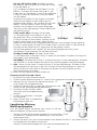
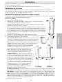
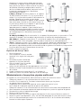
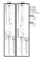
Tip ejection
To help eliminate the risk of contamination, each pipette is
fi tted with a tip ejector system. To release the tip, point the
pipette at suitable waste receptacle and press the tip ejector
with your thumb.
Adjusting the fi nger rest
The fi nger rest can be adjusted by rotating it 60 degrees
to both directions of the center position. Usually right
handed operators turn it left (counter clockwise) to get the
best possible position for the thumb to eject the tip. See
picture.
English
+
1
2

7
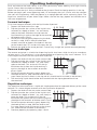
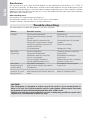
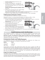
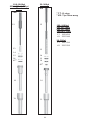
Pipetting techniques
Push and release the knob slowly at all times particularly when working with high viscosity
liquids. Never allow the knob to snap back.
Make sure that the tip is fi rmly attached to the tip cone. Check for foreign particles in the tip.
Before you begin your actual pipetting work, fi ll and empty the tip 2-3 times with the solution
that you will be pipetting. Hold the pipette in an upright position while aspirating liquid. The
fi nger rest should rest on your index fi nger. Make sure that the tips, pipette and solution are at
the same temperature.
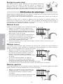
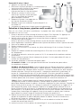
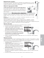
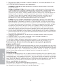
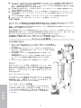
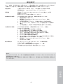
Forward technique
Fill a clean reagent reservoir with the liquid to be dispensed.
1 Depress the knob to the fi rst stop.
2. Dip the tip under the surface of the liquid in the
reservoir to a depth of about 1 cm and slowly
release the knob. Withdraw the tip from the
liquid touching it against the edge of the reservoir
to remove excess liquid.
3. Deliver the liquid by gently depressing the knob
to the fi rst stop. After a delay of about one
second, continue to depress the knob all the way
to the second stop. This action will empty the tip.
4. Release the knob to the ready position. If necessary, change the tip and continue pipetting.
Reverse technique
The reverse technique is suitable for dispensing liquids that have a high viscosity or a tendency
to foam easily. The technique is also recommended for dispensing very small volumes. Fill a
clean reagent reservoir with the liquid to be dispensed.
1. Depress the knob all the way to the second stop.
2. Dip the tip under the surface of the liquid in the
reservoir to a depth of about 1 cm, and slowly
release the knob. This action will fi ll the tip.
Withdraw the tip from the liquid touching it
against the edge of the reservoir to remove
excess liquid.
3. Deliver the preset volume by gently depressing
the knob to the fi rst stop. Hold the knob at the fi rst
stop. Some liquid will remain in the tip and this should not be included in the delivery.
4. The remaining liquid should either be discarded with the tip or pipetted back into
the container.
Repetitive technique
The repetitive technique offers a rapid and simple procedure for repeated delivery of the same
volume. Fill a clean reagent reservoir with the liquid to be dispensed.
1. Depress the knob all the way to the second stop.
2. Dip the tip under the surface of the liquid in the
reservoir to a depth of about 1 cm, and slowly re
lease the knob. This action will fi ll the tip.
Withdraw the tipfrom the liquid touching against
the edge of the reservoir to remove excess liquid.
3. Deliver the preset volume by gently depressing
the knob to the fi rst stop. Hold the knob at the
fi rst stop. Some liquid will remain in the tip and
this should not be included in the delivery.
4. Continue pipetting by repeating steps 3 and 4.
English
1 2 3 4
1 2 3 4
1 2 3 4

8
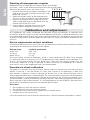
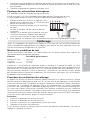
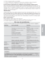
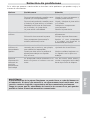
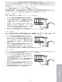
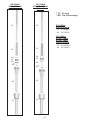
Pipetting of heterogeneous samples
(deproteinization in blood glucose determination, for example)
Use steps 1 and 2 of the forward technique to fi ll the tip with blood.
Wipe the tip carefully with a dry clean tissue.
1. Immerse the tip into the reagent and depress the
knob to the fi rst stop, making sure the tip is well
below the surface.
2. Release the knob slowly to the ready position.
This will fi ll the tip. Keep the tip in the solution.
3. Depress the knob to the fi rst stop and release
slowly. Keep repeating this procedure until the
interior wall of the tip is clear.
4. Finally, depress the knob all the way to the
second stop to completely empty the tip.
Calibration and adjustment
All Finnpipettes are factory calibrated and adjusted to give the volumes as specifi ed with
distilled or deionized water using the forward pipetting technique. It should be noted that the
use of other pipetting techniques may affect the calibration results. The pipettes are constructed
to permit re-adjustment for other pipetting techniques or liquids of different temperature and
viscosity.
Device requirements and test conditions
An analytical balance must be used. The scale graduation value of the balance should be chosen
according to the selected test volume of the pipette:
Volume range readable graduation
under 10 μl 0.00 1 mg
10-100 μl 0.01 mg
above 100 μl 0.1 mg
Test liquid: Water, distilled or deionized, “grade 3” water conforming ISO 3696. Tests are done
in a draft-free room at a constant (±0.5°C) temperature of water, pipette and air between 15°C
to 30°C. The relative humidity must be above 50%. Especially with volumes under 50 μl the
air humidity should be as high as possible to reduce the effect of evaporation loss. Special
accessories, such as the evaporation trap, are recommended.
Procedure to check calibration
The pipette is checked with the maximum volume (nominal volume) and with the minimum
volume. A new tip is fi rst pre-wetted 3-5 times and a series of ten pipettings is done with
both volumes. A pipette is always adjusted for delivery (Ex) of the selected volume. Use of
forward pipetting technique is recommended. The maximum permissible errors are designed for
forward method. It is recommended to calibrate all channels of the multichannel pipette, but a
suitable method is also to calibrate only the edge channels. Adjustment check prior calibration is
done using one of the middle channels. It is recommended to use the ISO8655 calibration limits
presented in the following tables or user-defi ned specifi cations.
Procedure:
1. Do 10 pipettings with the minimum volume.
2. Do 10 pipettings with the maximum volume.
3. Calculate the inaccuracy (A) and imprecision (cv) of both series.
4. Compare the results to the limits.
If the calculated results are within the selected limits, the adjustment of the pipette is correct.
English
1 2 3 4 5

9
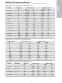
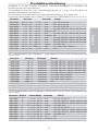
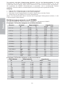
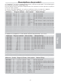
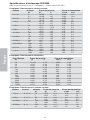
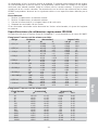
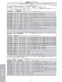
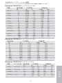
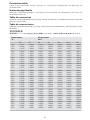
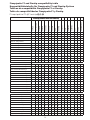
ISO8655 calibration specifi cations
Thermo Scientifi c Finnpipette F1 specifi cations according to ISO8655 standard.
Finnpipette F1 Variable Volume Single Channel
Range Volume Inaccuracy Imprecision
μl μl % s.d. μl cv%
0,2-2 μl 2 ±0.080 ±4 0.040 2.0
0.2 ±0.080 ±40 0.040 20.0
0,5-5 μl 5 ±0.125 ±2.5 0.075 1.5
0.5 ±0.125 ±25 0.075 15
1-10 μl 10 ±0.120 ±1.2 0.080 0.8
1 ±0.120 ±12 0.080 8.0
2-20 μl 20 ±0.20 ±1.0 0.10 0.5
2 ±0.20 ±10.0 0.10 5.0
5-50 μl 50 ±0.50 ±1.0 0.20 0.4
5 ±0.50 ±10 0.20 4.0
10-100 μl 100 ±0.80 ±0.8 0.30 0.3
10 ±0.80 ±8.0 0.30 3.0
20-200 μl 200 ±1.60 ±0.8 0.60 0.3
20 ±1.60 ±8.0 0.60 3.0
30-300 μl 300 ±4.0 ±1.3 1.5 0.5
30 ±4.0 ±13 1.5 5.0
100-1000 μl 1000 ±8.0 ±0.8 3.0 0.3
100 ±8.0 ±8.0 3.0 3.0
0,5-5 ml 5000 ±40.0 ±0.8 15.0 0.3
500 ±40.0 ±8.0 15.0 3.0
1-10 ml 10000 ±60.0 ±0.6 30.0 0.3
1000 ±60.0 ±6.0 30.0 3.0
Finnpipette F1 Fixed Volume Single Channel
Fixed Volume Inaccuracy Imprecision
μl μl % s.d.μl cv%
10 ±0.120 ±1.20 0.080 0.80
20 ±0.20 ±1.00 0.10 0.50
25 ±0.50 ±2.00 0.20 0.80
50 ±0.50 ±1.00 0.20 0.40
100 ±0.80 ±0.80 0.30 0.30
200 ±1.60 ±0.80 0.60 0.30
250 ±4.00 ±1.60 1.50 0.60
500 ±4.00 ±0.80 1.50 0.30
1000 ±8.00 ±0.80 3.00 0.30
2000 ±16.0 ±0.80 6.00 0.30
3000 ±40.0 ±1.33 15.00 0.50
5000 ±40.0 ±0.80 15.00 0.30
10000 ±60.0 ±0.60 30.00 0.30
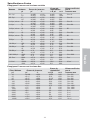
Finnpipette F1 Variable Volume Multichannel
Range Channel Volume Inaccuracy Imprecision
μl μl % s.d.μl cv%
1-10 μl 8, 12, 16 10 ±0.24 ±2.4 0.16 1.6
1 ±0.24 ±24 0.16 16
5-50 μl 8, 12, 16 50 ±1.0 ±2.0 0.4 0.8
5 ±1.0 ±20 0.4 8.0
10-100 μl 8, 12 100 ±0.80 ±0.8 0.30 0.3
10 ±0.80 ±8.0 0.30 3.0
30-300 μl 8, 12 300 ±8.0 ±2.7 3.0 1.0
30 ±8.0 ±26.7 3.0 10.0
English

10
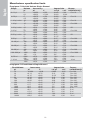
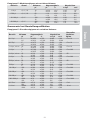
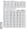
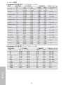
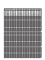
Manufacturer specifi cation limits
Finnpipette F1 Variable Volume Single Channel
Range Volume Inaccuracy Imprecision Factory
μl μl % s.d. μl cv% calibration tip
0.2-2 μl 2 ±0,050 ±2,50 0,040 2,00 Flex 10
0,2 ±0,024 ±12,00 0,020 10,00
0.5-5 μl 5 ±0,075 ±1,50 0,050 1,00 Flex 10
0,5 ±0,030 ±6,00 0,025 5,00
1-10 μl, micro 10 ±0,100 ±1,00 0,050 0,50 Flex 10
1 ±0,025 ±2,50 0,020 2,00
1-10 μl 10 ±0,100 ±1,00 0,080 0,80 Flex 200
1 ±0,035 ±3,50 0,030 3,00
2-20 μl, micro 20 ±0,20 ±1,00 0,08 0,40 50
2 ±0,06 ±3,00 0,05 2,50
2-20 μl 20 ±0,20 ±1,00 0,08 0,40 Flex 200
2 ±0,06 ±3,00 0,05 2,50
5-50 μl, micro 50 ±0,30 ±0,60 0,15 0,30 50
5 ±0,15 ±3,00 0,125 2,50
5-50 μl 50 ±0,30 ±0,60 0,15 0,30 Flex 200
5 ±0,15 ±3,00 0,125 2,50
10-100 μl 100 ±0,80 ±0,80 0,20 0,20 Flex 200
10 ±0,30 ±3,00 0,10 1,00
20-200 μl 200 ±1,2 ±0,60 0,4 0,20 Flex 200
20 ±0,36 ±1,80 0,14 0,70
30-300 μl 300 ±1,8 ±0,60 0,6 0,20 Flex 300
30 ±0,45 ±1,50 0,18 0,60
100-1000 μl 1000 ±6,0 ±0,60 2,0 0,20 Flex 1000
100 ±1,0 ±1,00 0,6 0,60
0,5-5 ml 5000 ±25,0 ±0,50 10,0 0,20 5 ml
500 ±10,0 ±2,00 4,0 0,80
1-10 ml 10000 ±50,0 ±0,50 20,0 0,20 10 ml
1000 ±20,0 ±2,00 8,0 0,80
Finnpipette F1 Fixed Volume Single Channel
Fixed Volume Inaccuracy Imprecision Factory
μl μl % s.d. μl cv% calibration tip
10 ±0,090 ±0,90 0,080 0,80 Flex 200
20 ±0,14 ±0,70 0,10 0,50 Flex 200
25 ±0,15 ±0,60 0,125 0,50 Flex 200
50 ±0,30 ±0,60 0,20 0,40 Flex 200
100 ±0,40 ±0,40 0,30 0,30 Flex 200
200 ±0,80 ±0,40 0,60 0,30 Flex 200
250 ±1,0 ±0,40 0,75 0,30 Flex 1000
500 ±1,5 ±0,30 1,5 0,30 Flex 1000
1000 ±3,0 ±0,30 3,0 0,30 Flex 1000
2000 ±6,0 ±0,30 4,0 0,20 5 ml
3000 ±9,0 ±0,30 6,0 0,20 5 ml
4000 ±12,0 ±0,30 8,0 0,20 5 ml
5000 ±15,0 ±0,30 10,0 0,20 5 ml
10000 ±30,0 ±0,30 20,0 0,20 10 ml
English

11
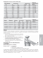
Finnpipette F1 Variable Volume Multichannel
Range Channels Volume Inaccuracy Imprecision Factory
μl μl % s.d. μl cv% calibration tip
1.0-10 μl 8, 12, 16 10 ±0,240 ±2,40 0,160 1,60 Flex 10
1 ±0,120 ±12,00 0,080 8,00
5-50 μl 8, 12, 16 50 ±0,75 ±1,50 0,35 0,70 Flex 200
5 ±0,25 ±5,00 0,10 2,00
10-100 μl 8, 12 100 ±1,30 ±1,30 0,50 0,50 Flex 200
10 ±0,50 ±5,00 0,20 2,00
30-300 μl 8, 12 300 ±3,0 ±1,00 0,9 0,30 Flex 300
30 ±1,5 ±5,00 0,6 2,00
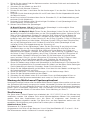
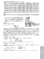
Adjustment
Adjustment is done only for one volume. The recommended adjustment volume is the minimum
volume or 10% of the maximum volume. Multichannel pipettes adjustment check prior
calibration is done using one of the middle channels.
1. Place the service tool into the openings of the
calibration nut at the top of the handle.
2. Turn the service tool clockwise to increase, or
counterclockwise to decrease the volume.
3. After adjustment check the calibration according
to the instructions above.
Formulas for calculating results
Conversion of mass to volume
V = (w + e) x Z V = volume (μl)
w = weight (mg)
e = evaporation loss (mg)
Z = conversion factor for μl/mg conversion
Evaporation loss can be signifi cant with low volumes. To determine mass loss, dispense water
to the weighing vessel, note the reading and start a stopwatch. See how much the reading
decreases during 30 seconds (e.g. 6 mg = 0.2 mg/s).
Compare this to the pipetting time from taring to reading. Typically pipetting time might be 10
seconds and the mass loss is 2 mg (10 s x 0.2 mg/s) in this example. If an evaporation trap or lid
on the vessel is used the correction of evaporation is usually unnecessary.
The factor Z is for converting the weight of the water to volume at test temperature and pressure.
A typical value is 1.0032 μl/mg at 22°C and 95 kPa. See the conversion table on page 62.
Inaccuracy (systematic error)
Inaccuracy is the difference between the dispensed volume and the selected volume of a pipette.
A = V - V0 A = inaccuracy
V = mean volume
V
0 = nominal volume
Inaccuracy can be expressed as a relative value: A% = 100% x A / V0
Imprecision (random error)
Imprecision refers to the repeatability of the pipettings. It is expressed as standard deviation (s)
or coeffi cient of variation (cv)
s = standards deviation
v = mean volume
n = number of measurements
Standard deviation can be expressed as a relative value (CV) CV = 100% x S / V
English
+

12
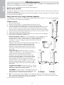
Maintenance
When the Finnpipette F1 is not in use, make sure it is stored in an upright position. We
recommend a Finnpipette stand for this purpose.
The part # refer to exploded views beginning at page 63.
Short-term service
The pipette should be checked at the beginning of each day for dust and dirt on the outside
surfaces of the pipette.
Particular attention should be paid to the tip cone. No other solvents except 70 % ethanol should
be used to clean the pipette.
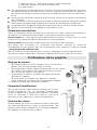
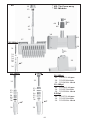
Long-term service, single channel pipettes
If the pipette is used daily it should be checked every three months. The servicing procedure
starts with the disassembly of the pipette.
2-1000 μl pipettes
1. Press the tip ejector.
2. Rotate the tip ejector 11 counterclockwise and pull it out.
3. Turn out the tip cone counterclockwise with the service tool.
4. Pull out the piston and other parts. Push out with piston the rest of the
piston assembly. Then turn the tip cone upside down and tap all parts
from tip cone. Remember keep all parts in order on table for reassembly.
5. Clean the piston, the piston spring and the O-rings with a dry napless cloth.
6. Check the tip cone for foreign particles.
7. Grease the cleaned parts with the lubricant that comes with the pipette.
8. Reassemble the pipette components.
0.2-2μl, 0.5-5μl & 1-10 μl: First, slide spring 22, o-ring support 23 and
o-ring 24 on the tube 21. With the 0.2-2μl model insert the tube 27
into the tube 21. Then slide the spring 13, spring support 16
and tubes 17 and 18, bigger o-ring 19 and smaller o-ring 20
back on the piston.
Compress the spring with fi ngers by pressing piston and
spring support 16 against each other and slide
the tube 21 with rest of the parts on the piston.
Hold the spring compressed and carefully slide
the entire assembly into the tip cone and release
the spring.
2-20 μl & 5-50 μl: Slide the spring 13, spring
support 16 and tubes 17 and 18, bigger o-ring 19
and smaller o-ring 20 back on the piston.
Compress the spring with fi ngers by pressing
piston and spring support 16 against each other
and slide the bigger o-ring 19, smaller o-ring 20,
spring support 21 and the spring 22 (smaller
diameter against spring support 21) on the piston.
Hold the spring compressed and carefully slide
the entire assembly into the tip cone and release
the spring.
10-100 μl & 20-200 μl: Slide the spring 13, spring
support 16 and o-ring 17 back on the piston. Slide
the entire assembly into the tip cone.
100-1000μl: Put the o-ring 17 and support ring 16 to
the tip cone. Slide the spring 13 on the piston and
slide the entire assembly into the tip cone.
9. All: Put the spring 15 and support 14 on top of the tip cone and carefully insert the tip
cone assembly to the handle. Attach the tip cone by turning it fi rst clockwise tight by hand,
then do the fi nal tightening with the service tool.
10. Reassemble the tip ejector.
English
1000μl
2-300μl
1
3
2

13
English
0.5-5ml & 1-10 ml pipettes
1. Press the tip ejector.
2. Rotate the tip ejector 10
counterclockwise to open it.
3. Disassemble the lower part of the tip
ejector 14 (snap fi tting).
4. Turn the cylinder 13 counterclockwise
and pull out the tip cone assembly.
5. Remove the cylinder 13 by pressing
the snaps fi ttings of the cylinder.
5. Clean and regrease the O-ring 12 and cylinder 13.
6. Assemble the parts in the opposite order of disassembly.
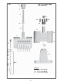
Long-term service, multichannel pipettes
If the pipette is used daily it should be checked and lubricated
every three months.
1. Place the service tool head#1 between ring 15 and ejector 23. Push the tool
until the partssnap from each other.
2. Check that the ejector lever is in up position and pull down the tip ejector part of the module.
Place the service tool head#2 in the hole of adapter tube 46.
3. Open the upper end of the tip ejector slightly and remove the tip ejector.
4. Screw out the module of the handle.
5. Remove the clip 22.
6. Press the spring 13 and remove the locking pieces 12 from the groove. Remove the spring 13.
7. Take off the locking claws 44 and 45 and pull out the adapter tube 46 and tube 43.
8. Use a screwdriver to remove the four screws 20,21 in the module cover and lift off
the cover.
9. Remove the piston bar 16 and clean the pistons 31 and tip cones 42 with a dry nap–free cloth.
10. If needed, service the tip cones:
16channel 1-10ul: The tip cones cannot be serviced, please replace if necessary.
30-300 μl, 10-100μl & 5-50 μl: Open the tip cone by carefully releasing the cover ring 32
from its snap joint with the screwdriver. Remove all the parts from the tip cone. Clean all
the parts. If needed, replace the o-rings. Take one piston. Slide the spring 33, cover ring 32
(larger hole), spring 34,, support ring 35, (o–ring 37 bigger 5-50μl/10-100μl) and o–ring 36
(smaller) onto the piston. Grease the o–ring with the lubricant provided in the pipette
package. Slide all the parts into the tip cone 30 and close the snap joint of the cover ring 32.
1–10 μl: Open the tip cone by carefully releasing the cover ring 32 from its snap joint with
the screwdriver. Remove all the parts from the tip cone. Clean all the parts. If needed,
replace the o-rings. Take one piston. Slide spring 33, cover ring 32 (larger hole), support 35,
o–ring 36 (bigger), o–ring 37 (smaller) and o–ring support 38 onto the piston. Then slide
spring 39, spring support 40 (sharp edges fi rst) and o–ring 41 onto the o–ring sup port 38.
Grease the o–rings with the lubricant provided in the pipette package. Slide all the parts
into the tip cone 30 and close the snap joint of the cover ring 32.
11. Install the piston bar with pistons and tip cones in the cover. Place aligning studs to the same
side when assembling the module. Close the cover with the four screws. Insert the clip 22.
12. Place the adapter tube 46 and tube 43 on the neck of the module and insert the locking
claws 44 and 45.
13. Insert spring 13 and locking pieces 12 to the piston rod 16.
14. Place the tip ejector on the module.
15. Screw the module in the handle and tighten with service tool head#2.
16. Push the tip ejector lever down, until you hear a “click”.
Service Instructions for Multichannel Pipette Tip Cones
To ensure even performance between all channels in a multichannel pipette, all tip cones have
to be changed at the same time, if any of them needs to be changed. Don’t mix tip cones of
different packages, because one bag contains a matched set of tip cones. Place aligning studs
to the same side when assembling the module. See picture on page 71.
1
2
3

14
CAUTION!
The Finnpipette is designed to allow easy in-lab service. If you would prefer to
have us or your local representative service your pipette, please make sure that
the pipette has been decontaminated before you send it to us.
Please note that the postal authorities in your country may prohibit or restrict the
shipment of contaminated material by mail.
Sterilization
The tip cone assy of a single channel pipette can be repeatedly autoclaved at 121°C (252°F)
(2 ata) for 20 minutes. All other parts and the multichannel pipettes are not autoclavable. After
autoclaving the tip cone assy must be cooled to room temperature for at least two hours. Before
pipetting, make sure that the tip cone assy is dry. We recommend that you check the calibration
after every sterilization cycle.
Autoclavable parts:
Part number 42: single channel tip cone assy
Excluding part number 10 and 14 on 0.5-5ml and 1-10ml models
The part numbers are presented in section Spare Parts.
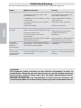
Trouble shooting
The table below lists possible problems and their solutions.
English
Defect
Leakage
Inaccurate
dispensing
Inaccurate
dispensing with
certain liquids
Dispensing knob
jammed to semi
down position
Possible reason
Tip incorrectly attached
Foreign particlesbetween tip and
tip cone
Foreign particles between the
piston, the O-ring and the cylinder
Insuffi cient amount of grease on
cylinder and O-ring
O-ring damaged
Incorrect operation
Tip incorrectly attached
Calibration altered: caused by
misuse, for example
Tip cone (Single channel) or
module (Multichannel) loose
Unsuitable calibration
High viscosity liquids may require
recalibration
One sided force applied to the knob
when adjusting the volume with one
hand
Solution
Attach fi rmly
Clean tip cones attach new tips
Clean and grease O-ring and
cylinder.
Grease accordingly
Change the O-ring
Follow instructions carefully
Attach fi rmly
Recalibrate according to
instructions
Tighten the tip cone or module
with the service tool.
Recalibrate with the liquids
in question
Pull up the knob and press down
again to locked position

15
Deutsch
Produktbeschreibung
Finnpipette F1 ist eine stufenlos einstellbare Mehrzweck-Mikropipette zur Entnahme und
Ausgabe genauer Flüssigkeitsmengen.
Sie funktioniert auf der Basis des Luftverdrängungsprinzips (d. h. einer Luftschnittstelle) und
verwendet abnehmbare Einwegspitzen.
Das einstellbare Ablaufvolumen wird in einer digitalen Anzeige am Griff dargestellt.
Die vierzehn Pipettenmodelle von Finnpipette F1 umfassen einen Volumenbereich von 0,2μl bis 10ml.
Bestellnr. Volumen Farbcode Finntip
4641010N 0,2 μl bis 2 μl rosa Flex 10, 10, 20, 50
4641020N 0,5 μl bis 5 μl rosa Flex 10, 10, 20, 50
4641030N 1 μl bis 10 μl rosa Flex 10, 10, 20, 50
4641040N 1 μl bis 10 μl gelb
Flex 200, 250 Univ., 200 Ext, 300, Flex 300
4641050N 2 μl bis 20 μl
turquioise
50
4641060N 2 μl bis 20 μl gelb
Flex 200, 250 Univ., 200 Ext, 300, Flex 300
4641130N 5 μl bis 50 μl
turquioise
50
4641140N 5 μl bis 50 μl gelb
Flex 200, 250 Univ., 200 Ext, 300, Flex 300
4641070N 10 μl bis 100 μl gelb
Flex 200, 250 Univ., 200 Ext, 300, Flex 300
4641080N 20 μl bis 200 μl gelb
Flex 200, 250 Univ., 200 Ext, 300, Flex 300
4641090N 30 μl bis 300 μl orange Flex 300, 300
4641100N 100 μl bis 1000 μl blau Flex 1000, 1000, 1000 Ext
4641110N 0,5 ml bis 5 ml grün 5 ml
4641120N 1 ml bis 10 ml rot 10 ml, Flex 10 ml Ext
Die 13 Pipettenmodelle von Finnpipette F1 Fixed Volume umfassen einen Volumenbereich von
1μl bis 10ml.
Bestellnr. Volumen Farbcode Finntip
4651020N 10 μl dunkelblau Flex 200, 250 Univ., 200 Ext, 300, Flex 300
4651130N 20 μl dunkelblau Flex 200, 250 Univ., 200 Ext, 300, Flex 300
4651030N 25 μl dunkelblau Flex 200, 250 Univ., 200 Ext, 300, Flex 300
4651040N 50 μl dunkelblau Flex 200, 250 Univ., 200 Ext, 300, Flex 300
4651050N 100 μl dunkelblau Flex 200, 250 Univ., 200 Ext, 300, Flex 300
4651140N 200 μl dunkelblau Flex 200, 250 Univ., 200 Ext, 300, Flex 300
4651060N 250 μl dunkelblau Flex 1000, 1000, 1000 Ext
4651070N 500 μl dunkelblau Flex 1000, 1000, 1000 Ext
4651080N 1000 μl dunkelblau Flex 1000, 1000, 1000 Ext
4651090N 2000 μl dunkelblau 5 ml
4651100N 3000 μl dunkelblau 5 ml
4651110N 5000 μl dunkelblau 5 ml
4651120N 10000 μl dunkelblau 10 ml, Flex 10 ml Ext
Die zehn Pipettenmodelle von Finnpipette F1 Multichannel umfassen einen Volumenbereich von
1 μl bis 300 μl.
Bestellnr.
Kanäle
Volume Range
Farbcode
Finntip
4661000N 8 1 μl bis 10 μl rosa Flex 10, 10, 20, 50
4661010N 8 5 μl bis 50 μl gelb
Flex 200, 250 Univ., 200 Ext, 300, Flex 300
4661020N 8 10 μl bis 100 μl gelb
Flex 200, 250 Univ., 200 Ext, 300, Flex 300
4661030N 8 30 μl bis 300 μl orange Flex 300, 300
4661040N 12 1 μl bis 10 μl rosa Flex 10, 10, 20, 50
4661050N 12 5 μl bis 50 μl gelb
Flex 200, 250 Univ., 200 Ext, 300, Flex 300
4661060N 12 10 μl bis 100 μl gelb
Flex 200, 250 Univ., 200 Ext, 300, Flex 300
4661070N 12 30 μl bis 300 μl orange Flex 300, 300
4661080N 16 1 μl bis 10 μl lila 20
4661090N 16 5 μl bis 50 μl
turquioise
50

16
Deutsch
Digitalanzeige
Die einstellbare Ablaufmenge ist in der großen digitalen
Anzeige am Griff zu sehen.
Materialien
Die Finnpipette F1 wird aus mechanisch dauerhaften und chemisch beständigen Materialien
hergestellt.
Für Informationen zur Abfallentsorgung wenden Sie sich bitte an Ihre örtliche Umweltbehörde.
Für nähere Informationen wenden Sie sich bitte an info.pipettes@thermofi sher.com.
Beschreibung der Spitzen
Für die Verwendung mit der Finnpipette F1 werden Finntips empfohlen.
Sie bestehen aus neuem, naturfarbenem Polypropylen, dem allgemein einzigen nicht
kontaminierenden
Material, das für Spitzen geeignet ist. Finntips sind ebenfalls autoklavierbar
(121°C).
Packungsinhalt
Die Finnpipette F1 wird in einer speziell konzipierten Verpackung transportiert und enthält die
folgenden Bestandteile:
1. Die Finnpipette
2. Wartungswerkzeug
3. Wartungswerkzeug für Mehrkanalpipetten
4. Finntip-Probe
5. Tasche Schmiermittel 1g (Bestellnr. 3300200)
6. Bedienungsanleitung
7. Kalibrierungszertifi kat / Garantiezertifi kat
8. Aufhängevorrichtung (Bestellnr. 2206040)
9. Zwei Aufkleber
Sicherheit
Warnungen sind mit diesem Symbol gekennzeichnet:
Vorgesehener Verwendungszweck
Die vorgesehene Verwendung des Produkts ist die Übertragung von Flüssigkeiten in Volumina
von 0,2 μl bis 10 ml.
Die Finnpipette F1 Pipette und die Finntips sind als Komponenten eines Analysesystems
konzipiert. Der Endbenutzer ist für die Validierung des Systems und die Sicherstellung korrekter
Ergebnisse verantwortlich.
Gesundheitsgefahren
Halten Sie die allgemeinen Sicherheitsvorschriften ein und tragen Sie angemessene
Schutzkleidung einschließlich Schutzbrille und -handschuhen.
Befolgen Sie bei der Entsorgung von Gefahrgut (z.B. radioaktive oder potentiell infektiöse
Substanzen) die Sicherheitsvorschriften und Laborregeln.
Die Pipette und ihre Spitzen sind nicht für In-vivo-Untersuchungen geeignet. Verwenden Sie
die Pipette niemals zum Injizieren von Flüssigkeiten in den menschlichen Körper.
Richten Sie die Pipette nicht auf Personen, wenn Sie die Spitze auswerfen.
Die Finnpipette F1 darf nur von geschultem Personal verwendet werden, das über entsprechende
Laborpraxis verfügt. Vor und während der Verwendung von Pipette und Spitze unbedingt die
Gebrauchsanleitung lesen! Die zulässige Betriebstemperatur der F1 liegt zwischen +4°C und
+40°C.

17
Falsche Dispensierergebnisse
Mögliche Gründe für Abweichungen:
a. Pipettiermethode (Direktmodus empfohlen)
b. Temperatur (Luft, Flüssigkeit, Pipette und Spitze).
c. Druck
d. Feuchtigkeit
e. Bediener (z.B. Daumenbewegung, Pipettierwinkel)
f. Flüssigkeitsdichte, Viskosität und Dampfdruck
g. Art der Spitze
Wenn die Pipettierleistung für die medizinische Diagnose entscheidend ist, muss das
Ergebnis des Diagnosetests durch einen weiteren Test verifi ziert werden, möglichst in
alternativem Verfahren. Die Möglichkeit eines inkorrekten Ablaufvolumens beim Pipettieren
kann nicht völlig ausgeschlossen werden.
Um Fehler und/oder Leckagen zu verhindern, vergewissern Sie sich, dass die Spitze korrekt
an der Pipette befestigt ist.
Überschreiten Sie beim Drehen des Volumenreglers nicht den zulässigen Maximalwert.
Andernfalls kann die Pipette Schaden nehmen oder ungenaue Ergebnisse produzieren.
Für wiederverwendete Pipettenspitzen wird keine Leistungsgarantie übernommen.
Die Farbcodierung von Pipette und Spitze muss übereinstimmen.
Entsorgung der Materialien
Befolgen Sie bei der Entsorgung biologischen Gefahrguts und radioaktiver Abfälle sowohl die
laborspezifi schen als auch die nationalen Vorschriften. Beachten Sie außerdem die örtlichen
Vorschriften für die Entsorgung infektiösen Materials.
Warnung Die Proben können ansteckende Keime enthalten. Entsorgen Sie alle Einwegspitzen
als biologisches Gefahrgut.
Warnung Dekontaminieren Sie die Pipette vor der Entsorgung.
Für Informationen zur Abfallentsorgung wenden Sie sich bitte an Ihre örtliche Umweltbehörde.
Für nähere Informationen wenden Sie sich bitte an info.pipettes@thermofi sher.com.
Bitte führen Sie die Originalverpackung und das darin enthaltene Verpackungsmaterial
sachgerechtem Recycling zu.
Weitere Informationen erhalten Sie bei Ihrer örtlichen Vertretung von ThermoFisher Scientifi c.
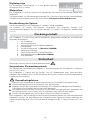
Bedienung der Pipette
Einstellen der Ablaufmenge
1. Die Ablaufmenge wird mit dem Knopf am oberen Ende der
Pipette eingestellt. Ziehen Sie den Knopf nach oben, um die
Mengeneinstellung zu aktivieren.
2. Um die Ablaufmenge zu erhöhen, drehen Sie den Knopf gegen
den Uhrzeigersinn. Um die Ablaufmenge zu verringern, drehen
Sie ihn im Uhrzeigersinn.
3. Wählen Sie keine Ablaufmenge, die außerhalb des für die Pipette
zulässigen Bereichs liegt.
Durch das gewaltsame Drehen des Knopfs außerhalb des
Bereichs kann der Mechanismus beschädigt und die Pipette
unbrauchbar werden.
4. Arretieren Sie die Mengeneinstellung, indem Sie den Knopf drücken.
Kennschild
Die Pipette ist mit einem Kennschild versehen, auf dem Sie Anwendung,
Kalibrierungsdatum, Ihre Initialen usw. vermerken können. Entfernen Sie
zum Austauschen des Kennschilds das Pipettenmodul. Beschriften Sie das
Etikett mit Bleistift und schieben Sie das Kennschild zusammen mit der
Halterung wieder in den Schlitz.
Deutsch
+
1
2

18
Auswerfen der Spitze
Um die Gefahr einer Kontamination auszuschließen, ist jede Pipette mit einem
Spitzen-Auswurfsystem ausgestattet. Um die Spitze zu lösen, halten Sie die Pipette
über einen geeigneten Abfallbehälter und drücken Sie den Spitzenauswerfer mit
dem Daumen nach unten.
Anpassung der Fingerstütze
Die Fingerstütze kann von der Mittelposition in beide
Richtungen um 60° gedreht werden. Für Rechtshänder
empfi ehlt es sich, die Stütze ein Stück weit nach links zu
drehen (gegen den Uhrzeigersinn), um die bestmögliche
Position für den Daumen zum Auswerfen der Spitze
einzustellen. Siehe Abbildung.
Pipettiermethoden
Das Drücken und Loslassen des Bedienungsknopfes muss stets langsam erfolgen,
insbesondere wenn mit hochviskosen Flüssigkeiten gearbeitet wird. Achten Sie
darauf, dass der Bedienungsknopf nie zurückschnappt.
Stellen Sie sicher, dass die Spitze fest in der Spitzenhalterung sitzt. Kontrollieren
Sie die Spitze auf Fremdkörper.
Bevor Sie mit dem Pipettieren beginnen, füllen und entleeren Sie die Spitze 2 -
3 Mal mit der Lösung, die Sie pipettieren wollen. Halten Sie die Pipette beim Ansaugen der
Flüssigkeit senkrecht. Ihr Zeigefi nger sollte auf dem griffi gen Bereich liegen. Achten Sie darauf,
dass die Spitze, die Pipette und die Lösung dieselbe Temperatur aufweisen.
Vorwärtsmethode
Füllen Sie ein sauberes Reagenzglas mit der Flüssigkeit, die pipettiert werden soll.
1. Drücken Sie den Knopf bis zum ersten Anschlag.
2. Tauchen Sie die Spitze ca. 1 cm unter die Oberfl äche der Flüssigkeit im Reagenzglas und
lassen Sie den Knopf langsam los. Nehmen Sie die Spitze aus der Flüssigkeit, wobei Sie
überschüssige Flüssigkeit am Rand des Glases abstreifen.
3. Gießen Sie die Flüssigkeit aus, indem Sie den
Knopf sanft bis zum ersten Anschlag drücken.
Drücken Sie nach etwa einer Sekunde den Knopf
ganz bis zum zweiten Anschlag durch. Dadurch
wird die Spitze entleert.
4. Lassen Sie den Knopf in die Ausgangsposition
zurückgleiten. Wechseln Sie nötigenfalls die
Spitze und fahren Sie mit dem Pipettieren fort.
Rückwärtsmethode
Die Rückwärtsmethode ist geeignet für Flüssigkeiten, die eine hohe Viskosität aufweisen oder
leicht schäumen. Diese Methode wird auch empfohlen, wenn nur sehr kleine Mengen verteilt
werden sollen. Füllen Sie ein sauberes Reagenzglas mit der Flüssigkeit, die pipettiert werden soll.
1. Drücken Sie den Knopf ganz durch bis zum zweiten Anschlag.
2. Tauchen Sie die Spitze ca. 1 cm unter die Oberfl äche der Flüssigkeit im Reagenzglas und
lassen Sie den Knopf langsam los. Dadurch wird die Spitze gefüllt. Nehmen Sie die Spitze
aus der Flüssigkeit, wobei Sie überschüssige Flüssigkeit am Rand des Glases abstreifen.
3. Gießen Sie die voreingestellte Flüssigkeitsmenge
aus, indem Sie den Knopf sanft bis zum ersten
Anschlag drücken. Halten Sie den Knopf am
ersten Anschlag fest. In der Spitze verbleibt etwas
Flüssigkeit, die nicht ausgegossen werden darf.
4. Die restliche Flüssigkeit wird entweder mit der
Spitze entsorgt oder zurück in den
Flüssigkeitsbehälter gegossen.
Wiederholungsmethode
Die Wiederholungsmethode bietet eine rasche und einfache Möglichkeit, dasselbe Volumen
mehrmals zu dosieren. Füllen Sie ein sauberes Reagenzglas mit der Flüssigkeit, die pipettiert
werden soll.
Deutsch
1 2 3 4
1 2 3 4

19
Deutsch
1. Drücken Sie den Knopf ganz durch bis zum
zweiten Anschlag.
2. Tauchen Sie die Spitze ca. 1 cm unter die
Oberfl äche der Flüssigkeit im Reagenzglas und
lassen Sie den Knopf langsam los. Dadurch wird
die Spitze gefüllt.
Nehmen Sie die Spitze aus der Flüssigkeit, wobei
Sie überschüssige Flüssigkeit am Rand des Glases
abstreifen.
3. Gießen Sie die voreingestellte Flüssigkeitsmenge
aus, indem Sie den Knopf sanft bis zum
ersten Anschlag drücken. Halten Sie den Knopf am ersten Anschlag fest. In der Spitze
verbleibt etwas Flüssigkeit, die nicht ausgegossen werden darf.
4. Fahren Sie mit dem Pipettieren fort, indem Sie die Schritte 3 und 4 wiederholen.
Pipettierung heterogener Proben
(z. B. Deproteinisation bei der Bestimmung des Blutzuckers)
Befolgen Sie Schritt 1 und 2 der Vorwärtsmethode um die Spitze mit Blut zu füllen.
Wischen Sie die Spitze sorgfältig mit einem trockenen, sauberen Tuch ab.
1. Tauchen Sie die Spitze in das Reagenzglas ein und drücken Sie den Knopf bis zum ersten
Anschlag. Achten Sie dabei darauf, dass die
Spitze unter die Oberfl äche der Flüssigkeit
eingetaucht ist.
2. Lassen Sie den Knopf langsam in die
Ausgangsposition zurückgleiten.
Dadurch wird die Spitze gefüllt. Halten Sie die
Spitze weiterhin in der Lösung.
3. Drücken Sie den Knopf bis zum ersten Anschlag
und lassen Sie ihn langsam los. Wiederholen Sie
diesen Vorgang, bis die Innenwand der Spitze klar ist.
4. Drücken Sie zum Schluss den Knopf ganz bis zum zweiten Anschlag durch, um die Spitze
vollständig zu entleeren.
Kalibrierung und Justierung
Alle Finnpipetten werden im Werk auf die spezifi zierten Mengen an destilliertem oder
vollentsalztem Wasser bei Verwendung der Vorwärtsmethode kalibriert und justiert.
Beachten Sie, dass die Verwendung anderer Pipettiermethoden die Kalibrierungsergebnisse
beeinfl ussen können. Die Pipetten sind so konzipiert, dass eine erneute Justierung für andere
Pipetiermethoden oder Flüssigkeiten vorgenommen werden kann, die eine unterschiedliche
Temperatur und Viskosität aufweisen.
Erforderliche Geräte und Prüfbedingungen
Zur Überprüfung wird eine Analysenwaage benötigt. Der Skalenwert der Waage muss
entsprechend der gewählten Testmenge der Pipette gewählt werden:
Menge Skala
unter 10 μl 0,001 mg
10-100μl 0,01 mg
über 100 μl 0,1 mg
Testfl üssigkeit: Destilliertes oder vollentsalztes Wasser der Klasse 3 gemäß ISO 3696. Die
Überprüfung wird in einem zugluftfreien Raum bei einer konstanten Temperatur von 15°C bis
30°C (±0,5°C) des Wassers, der Pipette und der Luft durchgeführt. Die relative Luftfeuchtigkeit
muss über 50% liegen. Insbesondere bei Mengen unter 50 μl sollte die Luftfeuchtigkeit möglichst
hoch sein, um Verdunstungsverluste zu vermeiden. Die Verwendung von Spezialzubehör, z.B.
eines Verdunstungsschutzes, wird empfohlen.
Prüfen der Kalibrierung
Die Pipette wird mit der Höchstmenge (Nennvolumen) und der Mindestmenge geprüft. Zuerst
wird eine neue Spitze drei- bis fünfmal mit Flüssigkeit durchspült. Dann wird mit beiden Mengen
eine Serie von zehn Pipettierungen durchgeführt. Eine Pipette ist stets auf den Ablauf (Ex) der
gewählten Menge justiert. Die Verwendung der Vorwärtsmethode wird empfohlen.
1 2 3 4
1 2 3 4 5

20
Deutsch
Die maximal zulässigen Abweichungen beziehen sich auf die Vorwärtsmethode. Es wird
empfohlen alle Kanäle einer Mehrkanalpipette zu kalibrieren, hilfsweise können auch nur die
Randkanäle kalibriert werden. Anpassungen werden dann mit den mittleren Kanälen vorgenommen.
Wir empfehlen die ISO8655 Kalibriergrenzen zu verwenden, wie in nachfolgenden Tabellen
aufgeführt. Alternativ können anwenderspezifi sche Kalibriergrenzen angewendet werden.
Vorgang:
1. Nehmen Sie 10 Pipettierungen mit der Mindestmenge vor.
2. Nehmen Sie 10 Pipettierungen mit der Höchstmenge vor.
3. Berechnen Sie die Ungenauigkeit (A) und die Unpräzision (cv) beider Serien.
4. Vergleichen Sie die Ergebnisse mit den Fehlergrenzen.
Wenn sich die berechneten Werte innerhalb der festgelegten Fehlergrenzen befi nden, ist die
Kalibrierung der Pipette korrekt.
Kalibrierungsgrenzwerte nach ISO8655
Die Spezifi kationen von Thermo Scientifi c Finnpipette F1 entsprechen ISO8655
Finnpipette F1-Einzelkanalpipette mit variablem Volumen
Bereich Volumen Ungenauigkeit Unpräzision
μl μl % s.d. μl cv%
0,2-2 μl 2 ±0.080 ±4 0.040 2.0
0.2 ±0.080 ±40 0.040 20.0
0,5-5 μl 5 ±0.125 ±2.5 0.075 1.5
0.5 ±0.125 ±25 0.075 15
1-10 μl 10 ±0.120 ±1.2 0.080 0.8
1 ±0.120 ±12 0.080 8.0
2-20 μl 20 ±0.20 ±1.0 0.10 0.5
2 ±0.20 ±10.0 0.10 5.0
5-50 μl 50 ±0.50 ±1.0 0.20 0.4
5 ±0.50 ±10 0.20 4.0
10-100 μl 100 ±0.80 ±0.8 0.30 0.3
10 ±0.80 ±8.0 0.30 3.0
20-200 μl 200 ±1.60 ±0.8 0.60 0.3
20 ±1.60 ±8.0 0.60 3.0
30-300 μl 300 ±4.0 ±1.3 1.5 0.5
30 ±4.0 ±13 1.5 5.0
100-1000 μl 1000 ±8.0 ±0.8 3.0 0.3
100 ±8.0 ±8.0 3.0 3.0
0,5-5 ml 5000 ±40.0 ±0.8 15.0 0.3
500 ±40.0 ±8.0 15.0 3.0
1-10 ml 10000 ±60.0 ±0.6 30.0 0.3
1000 ±60.0 ±6.0 30.0 3.0
Finnpipette F1-Einzelkanalpipette mit Konstantvolumen
Fixed Volume Ungenauigkeit Unpräzision
μl μl % s.d.μl cv%
10 ±0.120 ±1.20 0.080 0.80
20 ±0.20 ±1.00 0.10 0.50
25 ±0.50 ±2.00 0.20 0.80
50 ±0.50 ±1.00 0.20 0.40
100 ±0.80 ±0.80 0.30 0.30
200 ±1.60 ±0.80 0.60 0.30
250 ±4.00 ±1.60 1.50 0.60
500 ±4.00 ±0.80 1.50 0.30
1000 ±8.00 ±0.80 3.00 0.30
2000 ±16.0 ±0.80 6.00 0.30
3000 ±40.0 ±1.33 15.00 0.50
5000 ±40.0 ±0.80 15.00 0.30
10000 ±60.0 ±0.60 30.00 0.30
La page est en cours de chargement...
La page est en cours de chargement...
La page est en cours de chargement...
La page est en cours de chargement...
La page est en cours de chargement...
La page est en cours de chargement...
La page est en cours de chargement...
La page est en cours de chargement...
La page est en cours de chargement...
La page est en cours de chargement...
La page est en cours de chargement...
La page est en cours de chargement...
La page est en cours de chargement...
La page est en cours de chargement...
La page est en cours de chargement...
La page est en cours de chargement...
La page est en cours de chargement...
La page est en cours de chargement...
La page est en cours de chargement...
La page est en cours de chargement...
La page est en cours de chargement...
La page est en cours de chargement...
La page est en cours de chargement...
La page est en cours de chargement...
La page est en cours de chargement...
La page est en cours de chargement...
La page est en cours de chargement...
La page est en cours de chargement...
La page est en cours de chargement...
La page est en cours de chargement...
La page est en cours de chargement...
La page est en cours de chargement...
La page est en cours de chargement...
La page est en cours de chargement...
La page est en cours de chargement...
La page est en cours de chargement...
La page est en cours de chargement...
La page est en cours de chargement...
La page est en cours de chargement...
La page est en cours de chargement...
La page est en cours de chargement...
La page est en cours de chargement...
La page est en cours de chargement...
La page est en cours de chargement...
La page est en cours de chargement...
La page est en cours de chargement...
La page est en cours de chargement...
La page est en cours de chargement...
La page est en cours de chargement...
La page est en cours de chargement...
La page est en cours de chargement...
La page est en cours de chargement...
La page est en cours de chargement...
La page est en cours de chargement...
La page est en cours de chargement...
La page est en cours de chargement...
-
 1
1
-
 2
2
-
 3
3
-
 4
4
-
 5
5
-
 6
6
-
 7
7
-
 8
8
-
 9
9
-
 10
10
-
 11
11
-
 12
12
-
 13
13
-
 14
14
-
 15
15
-
 16
16
-
 17
17
-
 18
18
-
 19
19
-
 20
20
-
 21
21
-
 22
22
-
 23
23
-
 24
24
-
 25
25
-
 26
26
-
 27
27
-
 28
28
-
 29
29
-
 30
30
-
 31
31
-
 32
32
-
 33
33
-
 34
34
-
 35
35
-
 36
36
-
 37
37
-
 38
38
-
 39
39
-
 40
40
-
 41
41
-
 42
42
-
 43
43
-
 44
44
-
 45
45
-
 46
46
-
 47
47
-
 48
48
-
 49
49
-
 50
50
-
 51
51
-
 52
52
-
 53
53
-
 54
54
-
 55
55
-
 56
56
-
 57
57
-
 58
58
-
 59
59
-
 60
60
-
 61
61
-
 62
62
-
 63
63
-
 64
64
-
 65
65
-
 66
66
-
 67
67
-
 68
68
-
 69
69
-
 70
70
-
 71
71
-
 72
72
-
 73
73
-
 74
74
-
 75
75
-
 76
76


Thermo Scientific Finnpipette F1 Mode d'emploi
- Taper
- Mode d'emploi
dans d''autres langues
Documents connexes
Autres documents
-
 Thermo Fisher Scientific Finnpipette F1 Mode d'emploi
-
Gilson PIPETMAN P Manuel utilisateur
-
3M Electronic Pipettor II 6503, 5 mL, 1 ea Mode d'emploi
-
 Thermo Fisher Scientific PrepSEQ Nucleic Acid Sample Preparation Kit Mode d'emploi
-
Hach TenSette plus Manuel utilisateur
-
Brand S-8 Multi Channel Microlitre Pipette Transferpette Manuel utilisateur
-
Gilson PIPETMAN 8X200 Manuel utilisateur
-
Gilson P5000 Mode d'emploi
-
Mettler Toledo Pipette Calibration Module MCP-R Manuel utilisateur
-
 Vitlab pipeo Mode d'emploi


