GEBIH32-S2, GEBIH41-S2, GEBIH50-S2, GEBIH57-S2, GEBIH65-S2,
GEBIH71-S2, GEBI32-S2, GEBI41-S2, GEBI50-S2, GEBI57-S2,
GEBI65-S2, GEBI71-S2
2424
Volt
RETROFIT SIGN CONVERSION LED KIT FOR USE ONLY IN
ACCORDANCE WITH KIT INSTRUCTIONS.
KIT IS COMPLETE ONLY WHEN ALL PARTS REQUIRED BY
THE INSTRUCTIONS ARE PRESENT.
TROUSSE DE CONVERSION À DEL POUR LA
MODERNISATION DES ENSEIGNES
À UTILISER CONFORMÉMENT AU GUIDE D’INSTALLATION.
Save These Instructions
Use only in the manner intended by the manufacturer. If you have
any questions, contact the manufacturer.
Prepare Electrical Wiring
Electrical Requirements
• Acceptable for use in dry and damp locations.
• The grounding and bonding of the LED Driver shall be
done in accordance with National Electric Code (NEC)
Article 600.
• Follow all National Electric Codes (NEC) and local codes.
• These products are only suitable for connection to a
circuit from a Class 2 power source.
• These products have not been evaluated for use when
connected to a power source that does not comply with
Class 2 voltage and energy limited supplies.
BEFORE YOU BEGIN
Read these instructions completely and carefully.
EN
For the latest North American install guides for your product go to: https://products.LED.com/led-signage-lighting
For the latest European install guides for your product go to: https://products.LED.com/eu
BG Българската версия на инструкциите за инсталаця и
информация за безопасност могат да бъдат намерени
на следния адрес: https://products.LED.com/eu
CS Návod k montáží a bezpečnostní informace v češtině
najdete zde: https://products.LED.com/eu
DA Den danske version af installationsvejledningen og
sikkerhedsoplysninger kan findes på følgende placering:
https://products.LED.com/eu
DE Die deutsche Version der Installationsanleitung und
Sicherheitsinformationen finden Sie in folgendem Verzeic:
https://products.LED.com/eu
EL Μπορείτε να βρείτε την ελληνική εκδχή των οδηγιών
νγκατάστασης και των πληροφοριών ασφάλειας στην
εξής τοποθεσία: https://products.LED.com/eu
ES La versión española de las instrucciones de instalación y
la información sobre seguridad puede encontrarse en la
siguiente ubicación: https://products.LED.com/eu
ET Eestikeelse paigaldusjuhendi ja ohutusnñuded leiate
aadressilt: https://products.LED.com/eu
FI Asennusohjeiden ja turvallisuustietojen suomenkielinen
versio löytyy seuraavasta paikasta: https://products.LED.
com/eu
FR La version française des instructions d’installations et
information de sécurité est disponible à l’adresse suivante:
https://products.LED.com/eu
HR Hrvatska verzija priručnika za ugradnju i sigurnosnih
informacija nalazi se na sljedečoj lokaciji: https://products.
LED.com/eu
HU A telepítési útmutató és a biztnosági információk magyar
nyelvű változata az alábbi címen található: https://
products.LED.com/eu
IT La versione italiana del manuale di installazione e
sicurezza può essere reperita nella seguente sezione:
https://products.LED.com/eu
LT Lietuvišką diegimo instrukcijos ir saugos informacijos
versiją galima rasti šioje vietoje: https://products.LED.
com/eu
LV Uzstādīšanas instrukciju un drošības informāciju latviešu
valodā var atrast šeit: https://products.LED.com/eu
NL De Nederlandse versie van de installatie-instructies en
veiligheidsinformatie kan op de volgende locatie worden
gevonden: https://products.LED.com/eu
PL Polską wersję instrukcji instalacji oraz informacje
dotyczące bezpieczeństwa można znaleźć w następującej
lokalizacji: https://products.LED.com/eu
PT A versão em Português das instruções de instalação e
das informações de segurança pode ser encontrada na
seguinte localização: https://products.LED.com/eu
RO Versiunea în limba română a instrucţiunilor de instalare
şi a informaţiilor de siguranţă pot fi găsite la: https://
products.LED.com/eu
SV Ni hittar den svenska versionen av
installationsanvisningarna och säkerhetsinformationen på
följande plats: https://products.LED.com/eu
SL Previdnostna opozorila in varnostne informacije so na
zadnji strani vodnika za namestitev. Pred začetkom
namestitve izdelka jih skrbno preberite: https://products.
LED.com/eu
SK Slovenskú verziu montažnej príručky a bezpečnostnŷch
instrukcií nájdete na nasledujúcej lokalite: https://
products.LED.com/eu
FOR UL ONLY
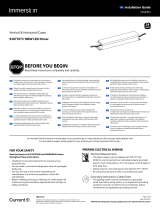
Slim EdgeStrip
LED Lighting System
Installation Guide
SIGN293 | DOC-2000639
EN