
1
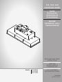
Use, Care, and
Installation Guide
Guide
d’utilisation,
d’entretien et
d’installation
Guía de
instalación, uso y
mantenimiento
READ AND SAVE THESE
INSTRUCTIONS
LISEZ CES
INSTRUCTIONS ET
CONSERVEZ-LES
LEA Y CONSERVE
ESTAS INSTRUCCIONES
LIB0190030
Printed in Mexico
Models: ETR628SS
ESC628SS
ESC134SS

2
APPROVED FOR RESIDENTIAL APPLIANCES
FOR RESIDENTIAL USE ONLY
READ AND SAVE THESE INSTRUCTIONS
PLEASE READ ENTIRE INSTRUCTIONS BEFORE PROCEEDING.
INSTALLATION MUST COMPLY WITH ALL LOCAL CODES.
IMPORTANT: Save these Instructions for the Local Electrical Inspector’s use.
INSTALLER: Please leave these Instructions with this unit for the owner.
OWNER: Please retain these instructions for future reference.
Safety Warning: Turn off power circuit at service panel and lock out panel, before wiring this appliance.
Requirement: 120 V AC, 60 Hz. 15 or 20 A Branch Circuit
Important Safety Notice ............................................................................................................................................................................ 3
Electrical & Installation requirements ..................................................................................................................................................... 4
Product Dimensions .................................................................................................................................................................................. 5
List of Materials ......................................................................................................................................................................................... 5
Ducting Options ......................................................................................................................................................................................... 6
Prepare the Location ................................................................................................................................................................................. 6
Install Range Hood into Hood Cabinet .................................................................................................................................................... 7
Electrical Connection ................................................................................................................................................................................ 8
Complete Installation ................................................................................................................................................................................ 8
Description of the Hood ............................................................................................................................................................................ 8
Control ........................................................................................................................................................................................................ 9
Maintenance ............................................................................................................................................................................................. 10
ENGLISH

3
Important Safety Notice
CAUTION
FOR GENERAL VENTILATING USE ONLY. DO NOT USE
TO EXHAUST HAZARDOUS OR EXPLOSIVE
MATERIALS OR VAPOURS.
WARNING
TO REDUCE THE RISK OF FIRE, ELECTRIC SHOCK, OR
INJURY TO PERSONS, OBSERVE THE FOLLOWING:
A. Use this unit only in the manner intended by the
manufacturer. If you have questions, contact the
manufacturer.
B. Before servicing or cleaning the unit, switch power off
at service panel and lock service panel disconnecting
means to prevent power from being switched on
accidentally. When the service disconnecting means
cannot be locked, securely fasten a prominent warning
device, such as a tag, to the service panel.
C. Installation Work and Electrical Wiring Must Be Done By
QualiedPerson(s)InAccordanceWithAllApplicable
Codes & Standards, Including Fire-rated Construction.
D. Sufcientairisneededforpropercombustionand
exhaustingofgasesthroughtheue(Chimney)offuel
burning equipment to prevent back- drafting.
Follow the heating equipment manufacturers guideline
and safety standards such as those published by the
NationalFireProtectionAssociation(NFPA),
theAmericanSocietyforHeating,
RefrigerationandAirConditioningEngineers(ASHRAE),
and the local code authorities.
E. When cutting or drilling into wall or ceiling, do not
damage electrical wiring and other hidden utilities.
F. Ducted fans must always be vented to the outdoors.
CAUTION
Toreduceriskofreandtoproperlyexhaustair,be
sure to duct air outside - do not vent exhaust air into
spaces within walls, ceilings, attics, crawl spaces, or
garages.
WARNING
TO REDUCE THE RISK OF FIRE, USE ONLY METAL
DUCT WORK.
Install this hood in accordance with all requirements
specied.
WARNING
To Reduce The Risk Of Fire Or Electric Shock, Do Not
UseThisHoodWithAnyExternalSolidStateSpeed
Control Device.
CAUTION
For models ETR628SS, ESC628SS use this hood only in
conjunction with ranges or range tops rated at maximum 78
KBTU's.
For model ESC134SS use this hood only in conjunction with
ranges or range tops rated at maximum 90 KBTU's.
WARNING
TO REDUCE THE RISK OF A RANGE TOP GREASE FIRE.
a) Never leave surface units unattended at high settings.
Boilovers cause smoking and greasy spillovers that may
ignite.Heatoilsslowlyonlowormediumsettings.
b) AlwaysturnhoodONwhencookingathighheator
whenambeingfood(I.e.CrepesSuzette,Cherries
Jubilee,PeppercornBeefFlambe’).
c) Clean ventilating fans frequently. Grease should not be
allowedtoaccumulateonfanorlter.
d) Useproperpansize.Alwaysusecookwareappropriate
forthesizeofthesurfaceelement.
WARNING
TO REDUCE THE RISK OF INJURY TO PERSONS, IN
THE EVENT OF A RANGE TOP GREASE FIRE,
OBSERVE THE FOLLOWING:a
a) SMOTHERFLAMESwithaclose-ttinglid,cookie
sheet, or other metal tray, then turn off the gas burner or
theelectricelement.BECAREFULTOPREVENT
BURNS.Iftheamesdonotgooutimmediately,
EVACUATEANDCALLTHEFIREDEPARTMENT.
b) NEVERPICKUPAFLAMINGPAN-youmaybe
burned.
c) DONOTUSEWATER,includingwetdishclothsor
towels - a violent steam explosion will result.
d) Use an extinguisher ONLY if:
1) YouknowyouhaveaclassABCextinguisher,and
you already know how to operate it.
2) Thereissmallandcontainedintheareawhereit
started.
3) Theredepartmentisbeingcalled.
4) Youcanghttherewithyourbacktoanexit.
aBasedon“KitchenFireSafetyTips”publishedbyNFPA.
OPERATION
a.Alwaysleavesafetygrillsandltersinplace.Without
these components, operating blowers could catch onto hair,
ngersandlooseclothing.
The manufacturer declines all responsibility in the event of
failure to observe the instructions given here for installation,
maintenance and suitable use of the product. The
manufacturer further declines all responsibility for injury due
to negligence and the warranty of the unit automatically
expires due to improper maintenance.
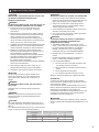
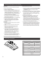
WARNING
ToReduceTheRiskOfFireAndElectricShock,InstallThis
RangehoodOnlyWithIntegralBlowerRatedMaximum7.6A/
913 W
IntegralBlower(alreadyincludedwiththehood)
HOODMODEL A W
ETR628SS 4.1 490
ESC628SS 4.1 490
ESC134SS 7.6 913

4
Electrical & installation requirements
IMPORTANT
Observe all governing codes and ordinances.
Itisthecustomer’sresponsibility:
• Tocontactaqualiedelectricalinstaller.
• To assure that the electrical installation is adequate and in
conformancewithNationalElectricalCode,ANSI/NFPA70—
latestedition*,orCSAStandardsC22.1-94,CanadianElectrical
Code,Part1andC22.2No.0-M91-latestedition**andalllocal
codes and ordinances.
• If codes permit and a separate ground wire is used, it is
recommendedthataqualiedelectriciandeterminethatthe
ground path is adequate.
• Do not ground to a gas pipe.
• Checkwithaqualiedelectricianifyouarenotsurerangehood
is properly grounded.
• Do not have a fuse in the neutral or ground circuit.
IMPORTANT
• SaveInstallationInstructionsforelectricalinspector’suse.
• The range hood must be connected with copper wire only.
• The range hood should be connected directly to the fused
disconnect(Orcircuitbreaker)boxthroughmetalelectrical
conduit.
• If provided with an electrical plug, connect the hood to a
receptacle that complies with current regulations and placed
in an accessible position. Where an electrical plug is not
provided(directconnectiontoelectricalnetwork)ortheplug
will not be in an accessible position after installation, place an
approved bipolar switch in accessible position that provides full
disconnection under overvolta- ge category III conditions, in
accordance with local wiring rules.
• WiresizesmustconformtotherequirementsoftheNational
ElectricalCodeANSI/NFPA70—latestedition*,orCSA
StandardsC22.1-94,CanadianElectricalCodePart1and
C22.2 No. 0-M91 - latest edition** and all local codes and
ordinances.
• AU.L.-orC.S.A.-listedconduitconnectormustbeprovidedat
eachendofthepowersupplyconduit(attherangehoodandat
thejunctionbox).
Copies of the standards listed may be obtained from:
*NationalFireProtectionAssociationBatterymarchParkQuincy,Massachusetts02269
**CSAInternational8501EastPleasantValleyRoadCleveland,Ohio44131-5575
BEFORE INSTALLING THE HOOD
1 Forthemostefcientairowexhaust,useastraightrunoras
few elbows as possible.
CAUTION:Ventunittooutsideofbuilding,only.
2 Atleasttwopeoplearenecessaryforinstallation.
3 Fittings material is provided to secure the hood to most types
ofwalls/ceilings,consultaQualiedInstaller,checkifthey
perfectlytwithyourcabinet/wall.
4 Donotuseexducting.
5 COLDWEATHERinstallationsshouldhaveanadditional
backdraftdamperinstalledtominimizebackwardcoldairow
andanonmetallicthermalbreaktominimizeconductionof
outside temperatures as part of the ductwork. The damper
should be on the cold air side of the thermal break. The break
should be as close as possible to where the ducting enters the
heated portion of the house.
6 Makeupair:Localbuildingcodesmayrequiretheuseof
Make-UpAirSystemswhenusingDuctedVentilationSystems
greaterthanspeciedCFMofairmovement.Thespecied
CFMvariesfromlocaletolocale.ConsultyourHVAC
professionalforspecicrequirementsinyourarea
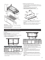
Product Dimensions
A
G
E
FI
D
C
B
H
J
J
Models
ESC628SS ETR628SS ESC134SS
A28½”(71.9cm) 34½”(87.6cm)
B153⁄4”(39.8cm) 18”(45.7cm) 153⁄4”(39.8cm)
C57⁄16”(13.8cm)
D61⁄2”(16.4cm)
E22"(56cm) 27 9⁄16”(70cm)
F12 3⁄8”(31.4cm)
G24" 5/16(61.8cm) 29 13⁄16”(75.7cm)
H10 1⁄16”(25.6cm)
I10”(25.4cm)
J3⁄4”(1.9cm)

5
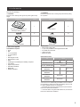
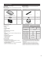
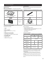
List of materials
Removing the packaging.
I CAUTION
Remove carton carefully, Wear gloves to protect against sharp
edges.
I WARNING
Removetheprotectivelmcoveringtheproductbeforeputting
into operation.
SuppliedPart Pieces SuppliedPart Pieces
Hoodassemblywithblowerand
LEDlampsalreadyinstalled
1
Side spacers
2
5x45mm 44x8 mm 10
10” round air transition
1
Greaselters
2
Parts not supplied
Tools/Materials required
• Level
• Drill
• 1¼”(3cm)drillbit
• ⅛”(3mm)drillbit
• Pencil
• Wire stripper or knife
• Tape measure or ruler
• Pliers
• Caulking gun and weatherproof caulking compound
• Ventclamps
• Jigsaw or keyhole saw
• Flat-blade screwdriver
• Metal snips
• Phillipsscrewdriver
Parts needed
• Homepowersupplycable
• ½”(12.7mm)ULlistedorCSAapprovedstrainrelief
• 3ULlistedwireconnectors
• 1 wall or roof cap
• Metal vent system
Optional Accesories
KIT Part#
ETR628SS ESC628SS ESC134SS
CFM Reduction Kit KIT0185097 KIT0185099
10" to 8" Transition Kit KIT0185271
1200 CFM External NO
Blower Kit KIT0179547
1200 CFM In-line NO
Blower Kit KIT0179549
1200 CFM External
Blower Kit KIT0153054
1200 CFM In Line
Blower Kit KIT0154387
*TherearenoHVIcertiedratingsavailableforthe8"transition
Kitconguration,pleasecheckwithlocalbuildingcodesinorder
toverifycompliancewithoutHVIcertication.
**CAUTION:WhenusingthisCFMreductionkit,themaximum
BTUuseforthishoodis65KBTU’s.
***CAUTION:WhenusingthisCFMreductionkit,themaximum
BTUuseforthishoodis78KBTU’s.

6
Ducting Options
Closelyfollowtheinstructionssetoutinthismanual.All
responsability,foranyeventualinconveniences,damagesorres
caused by not complying with the instructions in this manual, is
declined.
Preparation
Do not cut a joist or stud unless absolutely necessary. If a joist or
stud must be cut, then a supporting frame must be
constructed.
Fittings material is provided to secure the hood to most types of
walls/ceilings.
However,aqualiedtechnicianmustverifysuitabilityofthe
materialsinaccordancewiththetypeofwall/ceiling.
Before making cutouts, make sure there is proper clearance
within the ceiling or wall for exhaust vent.
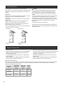
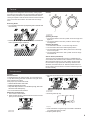
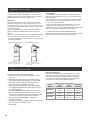
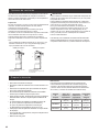
Thehoodisequippedwithan10”(25.4cm)roundtransitionfor
discharge of fumes to the outside.
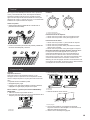
RoofVenting WallVenting
A
B
B
C
A
A.10”(25.4cm)roundvent
B. Wall cap
A.Wallcap
B.10”(25.4cm)roundvent
C. 90º elbow
CAUTION
For gas cooktop & range installations: Mount the hood so the
bottomisatleast30”(76.2cm)abovethecookingsurface.
Forelectric/inductioncooktop&rangeinstallations:Mountthe
hoodsothebottomisatleast24”(61cm)abovethecooking
surface.
There is no maximum mounting height, however, we recommend
mountingthehoodnogreaterthan36”(91.4cm)abovethe
cookingsurface.Foreveryinch(2.54cm)above36”(91.4cm),
fumeandmoisturecaptureefciencydiminishesatanincreasing
rate and may not deliver an acceptable level of ventilating
performance.
This hood is intended for household use.
PLEASEREADTHEINSTALLATIONMANUALFORSPECIFIC
APPLICATION.Checkyourceilingheightandhoodheightbefore
selecting your hood.
Prepare the location
• Disconnect power.
• Determine which venting method to use: roof or wall exhaust.
• Selectaatsurfaceforassemblingthehoodinsert.Place
covering over that surface.
• It is recommended that the vent system be installed before
hood is installed.
• Before making cutouts, make sure there is proper clearance
within the ceiling or wall for exhaust vent.
• Hoodinsertshouldbeinstalledaminimum24”(61cm)above
anelectriccooktopsurfaceand30”(76.2cm)aboveagascook
top surface. The maximum recommended height over both
cooktopsis36”(91.44cm).
• Check that all installation parts have been removed from the
shipping carton.
• Using 2 or more people, lift hood insert onto covered surface.
• Removethelters.Seethe“Cleaning”section.
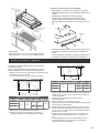
Dimensions and Clearances
Thisrangehoodhastheexibilitytobeinstalledintwodifferentways,dependingonthewidthmeasurementorworkingareabetween
the left and right cabinetry. Before beginning, it is important to determine the dimension of this working area and to consider the
measurements detailed in the next table.
Range Hood
Models
Range Hood
width without
spacers
Range Hood
width with
spacers
Range
Hood
Depth
ETR628SS 28½”
(72.3cm)
30 ”
(76.2cm)
153/4”
(39.8cm)
ESC628SS 28½”
(72.3cm)
30 ”
(76.2cm)
18"
(45.7cm)
ESC134SS 34½”
(87cm)
36”
(91.44cm)
153/4”
(39.8cm)

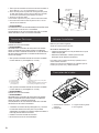
7
See
the
table
See the table
Hoodinsertcabinet
must be capable
of supporting
75lb(34kg)
“X” bottom of
canopy to
cooking surface
IMPORTANT:
Minimumdistance“X”:24”(61cm)fromelectriccooking
surfaces.
Minimumdistance“X”:30”(76.2cm)fromgascooking
surfaces.
Stainless Steel Hood Spacer Installation
• Youcanelongate1.5”(3.8cm)ofyourrangehoodwidth
(¾”[1.9cm]perside),installingthestainlesssteelspacers
included with your range hood.
• Unpack the spacer and take off the protective.
• Puteachoneontherightandtheleftside
• Fastenhoodspacerusingfour5x45mmscrewstothe
hood cabinet and tighten securely.
Hoodspacer
• Ifcabinetrydesignsreducesthewidthopening(i.e.-34.5”)to
install the hood, the spacers are not used.
• IfyouhaveaFullwidthopening(i.e.36)toinstallthehood,you
should use the spacers.
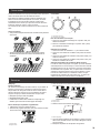
Install range hood into hood cabinet
The range hood attaches to the hood cabinet using four mounting
screws and washers.
NOTE:Hoodcabinetmustbecapableofsupporting
Prepare Range hood for mounting into cabinet
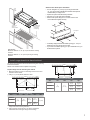
1 Mark the locations for the four mounting screws on the hood
cabinet as shown below.
2 Usinga⅛”(3mm)drillbit,drillthe4holes.
A
B
C
D
E
Wall
Centerline
MOUNTING HOLE DIMENSIONS
Model DIM A DIM B DIM C DIM D DIM E
ETR628SS
2″
(5cm)
101⁄16″
(25.6cm)
12 1⁄6″
(30.9cm)
24 1⁄3″
(61.8cm)
Ø 1⁄8″(3mm)
ESC628SS
ESC134SS 1415⁄16″
(37.9cm)
2913⁄16″
(75.8cm)
3 Mark the cutout for the rectangular clearance hole for the upper
range hood motor housing as shown.
4 Using a jigsaw or keyhole saw, cut out the rectangular
clearance hole for the upper range hood housing.
Wall
Centerline
A
B
C
D
UPPERHOOD MOTOR HOUSING DIMENSIONS
Model DIM A DIM B DIM C DIM D
ETR628SS
11⁄16″
(1.7cm)
12 1⁄2”
(31.7cm)
11 7/16"
(29cm)
22 13⁄16""
(58cm)
ESC628SS 11 7/16"
(29cm)
22 13⁄16""
(58cm)
ESC134SS 14 3⁄16”
(36cm) 28 5⁄16”
(72cm)

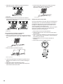
8
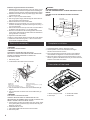
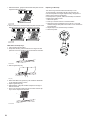
Install the range hood into the hood cabinet
1 Determine and make all necessary cuts in the wall or roof for
the vent system. Install the vent system before installing the
cabinethoodinsert.Seethe“VentingRequirements”section.
2 Determine the location where the power supply cable will be
run through the wall.
3 Drilla1¼”(3.2cm)holeatthislocation.
4 Pullenoughpowersupplycablethroughthewalltoallowfor
easy connection to the terminal box.
5 Remove terminal box cover and set aside.
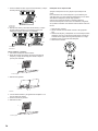
6 Installthe10”(25.4cm)squarex10”(25.4cm)roundvent
transition with damper to top side of the range hood, using 4 -
3.5x9.5mmscrews.
7 Remove knockout from the top of the vent hood and install a
ULlistedorCSAapproved½”(1.3cm)strainrelief.
8 Placethehoodinsertnearitsmountingpositionandrunthe
power supply cable through the strain relief into terminal box
(enoughtomakeconnection).
9 Tighten the strain relief screws.
10 Using 2 or more people, lift the hood insert into hood cabinet.
11 Fastenthehoodinsertusingfour5x45mmscrewstothe
hood cabinet and tighten securely.
WARNING
EXCESSIVE WEIGHT HAZARD
USE TWO OR MORE PEOPLE TO MOVE AND INSTALL HOOD
INSERT.
FAILURE TO DO SO CAN RESULT IN BACK OR OTHER
INJURY.
UpperHood
InsertMotorHousing
4 mounting
screws
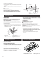
Electrical connection
I WARNING
ELECTRICALSHOCKHAZARD.
I WARNING
DISCONNECTPOWERBEFORESERVICING.
REPLACEALLPARTSANDPANELSBEFOREOPERATING.
FAILURETODOSOCANRESULTINDEATHOR
ELECTRICALSHOCK.
1 Disconnect power.
2 Locateterminalboxinsideofthehoodinsert.
A
B
C
D
E
G
F
A.Whitewires
B. Black wires
C.ULlistedwireconnectors
D.Green,bareoryellow/greenwires
E.Homepowersupply
F.ULlistedorCSAapproved¹⁄2”(1.3cm)
strain relief
G. Ground Wire tab
3 UseULlistedwireconnectorsandconnectblackwires(B)
together.
4 UseULlistedwireconnectorsandconnectwhitewires(A)
together.
I WARNING
ELECTRICALLYGROUNDBLOWER.
CONNECTGROUNDWIRETOGREENANDYELLOW
GROUNDWIREINTERMINALBOX.FAILURETODOSOCAN
RESULTINDEATHORELECTRICALSHOCK.
5 Connectgreen(orbare)groundwirefromhomepowersupply
tothegreen/yellowgroundwire(D)interminalboxusingUL
listed wire connectors.
6 Install terminal box cover.
7 Check that all light bulbs are secure in their sockets.
8 Reconnect power.
1 Installgreaselters.Seethe“Cleaning”section.
2 CheckoperationoftheHoodInsertblowerandlights.
Seethe“HoodInsertUse”section.
3 If the hood insert does not operate, check to see whether a
circuit breaker has tripped or a house hold fuse has blown.
4 Disconnect power supply and check that the wiring is correct.
NOTE:Togetthemostefcientusefromyournewhoodinsert,
readthe“HoodInsertUse”section.
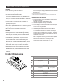
Description of the hood
1
4
3
2
1 Blower and light controls
2 LEDlamps
3 Greaselterhandle
4 Greaselter
Complete installation

9
Control.
The range hood is designed to remove smoke, cooking vapors
and odors from the cooktop area. For best results, start the hood
before cooking and allow it to operate several minutes after the
cooking is complete to clear all smoke and odors from the kitchen.
The hood controls are located on the center side of the range
hood.
Recessing Knobs
• Youcanhidecontrolknobsbydepressingthemuntilushwith
the hood body.
• Pressingtheknobsagainwilllowertheknobs,andenablethe
user to operate the lights and blower.
Controls
A B
A.Lampsknob
B. Blower knob
Operating the lamps
1 Turn the light switch to the “ON” position to turn the range hood
lights On.
2 Turn the light switch to the “OFF” position to turn the range
hood lights Off.
Operating the blower
1 Turn the blower switch at “1” to turn the range hood on.
2 Turn the blower switch to the desired speed position.
3 Turntheblowerswitchtothe“MAX”positiontoturntherange
hood on max speed.
4 Turn the blower switch to the “OFF” position to turn the range
hood blower Off.
Auto On blower (Heat Guard)
The range hood is equipped with a sensor to automatically turn
on the blower when excessive heat is detected in the control area.
When the blower switch is in the “Off” position, this sensor will
turn the blower to high speed when necessary. When the heat
decreases, the blower will turn off. When the blower switch is in
the On position, the heat sensor is not active and the range hood
functions normally.
Maintenance
Cleaning
Exterior surfaces:
To avoid damage to the exterior surface, do not use steel wool
orsoap-lledscouringpads.Rubindirectionofthegrainlineto
avoid scratching the surface.
Alwayswipedrytoavoidwatermarks.
• StainlessSteelCleanerandPolish.
• Mild liquid detergent and water.
• Wipe with damp soft cloth or non abrasive sponge, then rinse
with clean water and wipe dry.
• Do not use chlorine base cleaners.
Metal Filters and Drip Trays:
1 Use2handstoremovelters.
2 Graspthelterhandles,pulltowardthefrontofthehoodand
pull up on the rear handle.
A
1
2B
A.Fronthandle
B. Rear handle
3 Pulldownandforwardonthehoodfronthandletoremovethe
lter.
3
4
A
B
5
A
B
A.Fronthandle
B. Rear handle
4 Remove grease drip tray.
A
A.Driptray
5 Washmetalltersandgreasetraysasneededindishwasher
or hot detergent solution to clean.
6 Replace grease drip tray.

10
7 Reinstallthelters,graspthelterhandlesandplacetheback
edgeofthelterintothehood.
1
A
B
A.Fronthandle
B. Rear handle
8 Pushupandbackontherearhandleandplacethebackofthe
lterintothedrippantosecureit.Repeatforeachlter.
2
3
A
B
A
4
B
A.Fronthandle
B. Rear handle
Metal Filters and Drip Trays:
1 Use2handstoremovelters.
2 Grasplterhandles,pulltowardthefrontofrangehoodand
pulldownontherearhandletoremove.Repeatforeachlter.
A
A.Greasefilter
3 Remove grease drip tray.
A
A.Driptray
4 Washmetalltersandgreasetraysasneededindishwasher
or hot detergent solution to clean.
5 Replace grease drip tray.
6 Reinstalllters,grasplterhandlesandplacefrontedgeof
lterintothehood.
7 Pushuponthebackhandleandsetrearoflterintothedrip
traytosecure.Repeatforeachlter.
A
A.Greasefilter
Replacing a LED Lamp
TurnofftherangehoodandallowtheLEDlamptocool.
To avoid damage or decreasing the life of the new lamp, do
nottouchlampwithbarengers.Replacelamp,usingtissueor
wearing cotton gloves to handle lamp.
If new lamps do not operate, make sure the lamps are inserted
correctly before calling service.
1 Disconnect power.
2 Pushuponthelensandturnitcounterclockwise.
3 Removethelampandreplaceitwitha120-volt,7.5Wwatt
maximum halogen lamp with a GU10 base. Turn it clockwise to
lock it into place.
4 Repeat steps 2-3 for the other lamps if needed.
5 Reconnect power.

11
ELICA North America
TWO-YEAR LIMITED WARRANTY
TO OBTAIN SERVICE UNDER WARRANTY
Owner must present proof of original purchase date. Please keep a copy of your dated proof of purchase (sales slip) in
order to obtain service under warranty.
PARTS AND SERVICE WARRANTY
For the period of two (2) years from the date of the original purchase, Elica will provide free of charge, non consumable
parts or components that failed due to manufacturing defects. During these two (2) years limited warranty, Elica will also
provide free of charge, all labor and in-home service to replace any defective parts.
WHAT IS NOT COVERED
• Damage or failure to the product caused by accident or act of God, such as, flood, fire or earthquake.
• Damage or failure caused by modification of the product or use of non-genuine parts.
• Damage or failure to the product caused during delivery, handling or installation.
• Damage or failure to the product caused by operator abuse.
• Damage or failure to the product caused by dwelling fuse replacement or resetting of circuit breakers.
• Damage or failure caused by use of product in a commercial application.
• Service trips to dwelling to provide use or installation guidance.
• Light bulbs, metal or carbon filters and any other consumable part.
• Normal wear of finish.
• Wear to finish due to operator abuse, improper maintenance, use of corrosive or abrasive cleaning products/pads and
• When the product has not been operated in accordance with the accompanying instructions for use.
oven cleaner products.
WHO IS COVERED
This warranty is extended to the original purchaser for products purchased for ordinary residential use in North America
(Including the United States, Guam, Puerto Rico, US Virgin Islands & Canada).
This warranty is non-transferable and applies only to the original purchaser and does not extend to subsequent owners of
the product. This warranty is made expressly in lieu of all other warranties, expressed or implied, including, but not limited
to any implied warranty of merchantability or fitness for a particular purpose and all other obligations on the part of Elica
North America, provided, however, that if the disclaimer of implied warranties is ineective under applicable law, the dura-
tion of any implied warranty arising by operation of law shall be limited to two (2) years from the date of original purchase
at retail or such longer period as may be required by applicable law.
This warranty does not cover any special, incidental and/or consequential damages, nor loss of profits, suered by the
original purchaser, its customers and/or the users of the Products.
WHO TO CONTACT
To obtain service under warranty or for any service related question:
USA & CANADA - Western Provinces
SERVICE POWER
888 732 8018
CANADA - Ontario Province
AGI Services
888 651 2534
CANADA - Quebec & Atlantic Provinces
Ateliers G. Paquette
800 463 0119
•
•
To ensure prompt after-sales service, when you call we will kindly ask you to provide the following information indicated
on the nameplate inside the hood: hood model, 12 NC and date of purchase on original invoice.To access the nameplate,
all you have to do is remove the grease filters.
•
Register your product in
elica.com
and earn a 3rd year of factory
warranty, covering all parts
plus in-home labor.
12NC:
Hood model:
Serial No:
Date of purchase on original invoice:

12
APPROUVÉ POUR LES APPAREILS DE TYPE RÉSIDENTIEL
POUR UNE UTILISATION RÉSIDENTIELLE SEULEMENT
LISEZ CES INSTRUCTIONS ET CONSERVEZ-LES
VEUILLEZ LIRE CES INSTRUCTIONS AU COMPLET AVANT DE COMMENCER.
L’INSTALLATION DE L’APPAREIL DOIT RESPECTER TOUS LES CODES EN VIGUEUR.
IMPORTANT : Conservezcesinstructionsandepouvoirlesremettreàl’inspecteur-électriciendevotrerégion.
INSTALLATEUR : Veuillezlaissercesinstructionsavecl’appareilpourlepropriétaire.
PROPRIÉTAIRE : Veuillezconservercesinstructionspourpouvoirvousyréférerplustard.
Avertissement de sécurité : Coupezl’alimentationducircuitdanslepanneauélectriqueetverrouillezle
panneauavantderaccorderleslsdecetappareil.
Exigence : 120Vc.a.,60Hzcircuitdedérivationde15Vc.a.,20Hz,de15ou20A.
Avis de sécurité important ..................................................................................................................................................................... 13
Exigences Électriques et D'Installation ................................................................................................................................................ 14
Dimensions du Produit ........................................................................................................................................................................... 15
Liste des Pièces....................................................................................................................................................................................... 15
Méthodes d’évacuation ........................................................................................................................................................................... 16
Préparer l'emplacement .......................................................................................................................................................................... 16
Installation de la caisse de la hotte ....................................................................................................................................................... 17
Connexion Électrique .............................................................................................................................................................................. 18
Achever l’installation .............................................................................................................................................................................. 18
Description de la hotte ............................................................................................................................................................................ 19
Commandes ............................................................................................................................................................................................. 19
Entretien ................................................................................................................................................................................................... 20
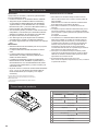
I AVERTISSEMENT
Pourréduirelesrisquesd’incendieetdechocélectrique,installezcettehottequ’aveclesmodèlesdemoteursinternes,enligne
etexternesd’uneportéemaximalede7.6A/913W,oudemoteursinternes(pourlesmodèlesderéférence,voirletableaudes
accessoiresfacultatifs).
Moteur interne
(inclusaveclehotte)
MODÈLEDEHOTTE A W
ETR628SS 4.1 490
ESC628SS 4.1 490
ESC134SS 7.6 913
FRANÇAIS

13
Avis de sécurité important
I ATTENTION
UTILISER CET APPAREIL À DES FINS DE VENTILATION
GÉNÉRALE SEULEMENT. NE PAS UTILISER CET
APPAREIL POUR ÉVACUER DES MATÉRIAUX OU DES
VAPEURS DANGEREUX OU EXPLOSIFS.
I AVERTISSEMENT
POUR RÉDUIRE LES RISQUES D’INCENDIE, DE CHOC
ÉLECTRIQUE ET DE BLESSURE, RESPECTER LES
DIRECTIVES SUIVANTES :
A. Utilisercetappareiluniquementauxnsprévuesparlefabri
cant.Sivousavezdesquestionsàproposdel’appareil,commu-
niquezaveclefabricant.
B. Avantdefairel’entretiendel’appareiloudelenettoyer,
coupezl’alimentationdanslepanneauélectriqueetverrouillezle
panneauenbloquantledispositifpermettantd’empêcherd’activer
l’alimentationaccidentellement.S’iln’estpaspossibledever-
rouillerl’accèsaupanneau,xezuneétiquettetrèsvoyanteau
panneauélectrique.
C. Unepersonnequaliéedoiteffectuerl’installationetle
câblagedeslsélectriquesenconformitéavectouslescodeset
touteslesnormes,ycomprislacotederésistanceaufeu.
D. Ilestimportantdeprévoirsufsammentd’airpouras-
surerunebonnecombustiondel’équipementde chauffe
etl’évacuationadéquatesdesgazparleconduitdecheminéan
deprévenirlesrefoulementsd’air.Respectezlesdirectivesetles
normesdesécuritédesfabricantsdel’équipementdechauffage,
commecellespubliéesparlaNationalFireProtectionAssocia-
tion(NFPA),laAmericanSocietyforHeating,Refrigerationand
AirConditioningEngineers(ASHRAE)etlecodedesautoritésde
votrerégion.
E. Aumomentdecouperoudepercerunmurouunplafond,
assurez-vousdenepasendommagerlalerieélectriqueoutout
autreaccèsàunservicepublique.
F. Ilfauttoujoursévacueràl’extérieurlessystèmesàcon-
duit.
I ATTENTION
Pourréduirelesrisquesd’incendieetévacuerl’air
correctement,assurez-vousqueleconduitmèneàl’extérieur;il
nefautpasévacuerl’airdansl’espaceentrelesmurs,dansles
plafonds, dans les greniers, les vides sanitaires ou les garages.
I AVERTISSEMENT
POURRÉDUIREDESRISQUESD’INCENDIE,UTILISEZ
UNIQUEMENTDESCONDUITSENMÉTAL.
Installezcettehotteenrespectanttouteslesexigences
mentionnées.
I AVERTISSEMENT
Pourréduirelesrisquesd’incendieetdechoc
électrique,n’utilisezpascettehotteavecuncontrôleur
devitesseàsemi-conducteurs.
I ATTENTION
PourlesmodèlesETR628SSetESC628SSutilisezcettehotte
uniquementavecdescuisinièresoudesdessusdecuisinière
d'unecapacitémaximalede78KBTU.
PourlemodèleESC134SS,utilisezcettehotteuniquement
avecdescuisinièresoudesdessusdecuisinièred'unecapacité
maximale de 90 KBTU.
I AVERTISSEMENT
POUR RÉDUIRE LES RISQUES D’INCENDIE DE GRAISSE
SUR LES CUISINIÈRES.
a) Nelaissezjamaislacuisinièresanssurveillancelorsqu’elle
estrégléeàunehautetempérature.Lesdébordementsparbouil-
lonnementcausentdelafuméeetdesdébordementsdegras
quipeuvents’enammer.Faiteschaufferl’huilelentement,àune
températurebasseoumoyenne.
b) Faitestoujoursfonctionnerlahottelorsquevousutilisezlacui-
sinièreàunehautetempératureouquevousfaitesamberdes
aliments(P.ex.:crêpesSuzette,cerisesjubilées,boeufaupoivre
ambé).
c) Nettoyezleshélicesdeventilationfréquemment.Ilnefautpas
quelagraisses’accumulesurleslresouleshélices.
d) Utilisezlebonformatdecasserole.Utiliseztoujoursun
chaudrondetailleappropriéàl’élémentdelacuisinière.
I AVERTISSEMENT
POURÉVITERDEBLESSERQUELQU’UNLORSD’UN
INCENDIEDEGRAISSESURLACUISINIÈRE,SUIVRE
LESCONSEILSSUIVANTS:a
a) ÉTOUFFERLESFLAMMESavecuncouvercleauxdimen-
sionsdelataquedecuisson,unetôleàbiscuitoutoutautrepla-
teaumétallique,puiscouperlegazoul’alimentationélectriquede
lacuisinière.FAIREATTENTIONANEPASSEBRÛLER.Siles
ammesnes’éteignentpasimmédiatement,QUITTERLAPIÈCE
ETAPPELERLESPOMPIERS.
b) NEJAMAISPRENDREENMAINUNECASSEROLEEN
FEU,vouspourriezvousblesser.
c) NEPASUTILISERD’EAU,ycomprislesessuiesdevais-
selleoulesservietteshumides–uneviolenteexplosiondueàla
vapeurforméepourraitsurvenir.
d) UtiliserunextincteurSEULEMENTsi:
1) Vousêtessûrd’avoirunextincteurdeclasseABCque
voussavezutiliser.
2) Lefeuestpetitetconnéàlazoneoùils’estformé.
3) Lespompiersontétéappelés.
4) Vouspouvezluttercontrelefeuavecunesortie
derrièrevous.
aRecommandationstiréesdesconseilsdesécuritéencas
d’incendiedecuisinepubliésparlaNFPA.
MODE OPÉRATOIRE
a) Toujourslaisserlesgrillesdesécuritéetlesltresàleurplace.
Sanslaprésencedecesderniers,lespartiesaspirantespour-
raientattirerlescheveux,lesdoigtsoulesvêtements.
Lefabricantdéclinetouteresponsabilitésilesinformations
détailléesdanscemanuelpourl’installation,l’entretienet
l’utilisationadéquateduproduitnesontpasobservées.Le
fabriquantdéclineenoutretouteresponsabilitépour
d’éventuellesblessuresduesàdesnégligences;enoutre,la
garantiedel’appareilseraannuléesuiteàdesconditions
d’entretieninappropriées.Cetappareilestfabriquépourun
usageinterne.Nepasutilisercetappareilàl’extérieur.
LISEZ CES INSTRUCTIONS ET CONSERVEZ-LES

14
Exigences Électriques et d'Installation
IMPORTANT
Respecteztouslescodesetlesordennancesenvigueur.
Leclientalaresponsabilitéde:
• Contacterunélectricien-installateur.
• Vérierquel’installationélectriqueestadéquateetconfor-
meavecleCodenationaldel’électricité,ANSI/NFPA
70(laplusrécenteédition*),oulesnormesC22.1-94,Code
canadiendel’électricité,Partie1etC22.2No.0-M91
(Laplusrécenteédition**)delaCSA,ainsiquetousles
codesetlesordonnancesdevotrerégion.
• Silecodelepermetetquevousutilisezunldemise
àlaterredistinct,ilestrecommandédefairevérierle
chemindulparunélectricien.
• Nepasmettrel’appareilàlaterresuruneconduitedegaz.
• Consultezunélectricienqualiésivousn’êtespas
certainquelahotteestmiseàlaterrecorrectement.
• N’installezpasunfusibledanslecircuitneutreoule
circuitdemiseàlaterre.
IMPORTANT
• Conservezcesinstructionsandepouvoirlesremettreà
l’inspecteur-électricien.
• Lahottedoitêtrecâbléeuniquementàl’aidedelsde
cuivre.
• Ilfautraccorderlahottedirectementàuneboîteà
fusibleouàundisjoncteurparl’entremised’une
canalisationélectriqueenmétal.
• Lecalibredeldoitêtreconformeauxexigencesdu
Codenationaldel’électricité,ANSI/NFPA70(Laplus
récenteédition*),oulesnormesC22.1-94,Code
canadiendel’électricité,Partie1etC22.20-M91(La
plusrécenteédition**)delaCSA,ainsiquetousles
codesetlesordonnancesdevotrerégion.
• Ilfautprévoirunconnecteurdecanalisationapprouvé
parl’ULoulaCSAàchaqueextrémitédelacanalisation
d’alimentation(Àlahotteetàlaboîtedejonction).
Vouspouvezobtenirunexemplairedesnormesindiquéesenvousadressantà:
*LaNationalFireProtectionAssociation,BatterymarchParkQuincy,Massachusetts,02269
**LaCSAInternational,8501EastPleasantValleyRoad,Cleveland,Ohio,44131-5575
AVANT D’INSTALLER LA HOTTE
1 Pourassurerlaventilationlaplusefcacepossible,installezla
conduite en ligne droite ou avec le moins decoudes possibles.
1 I ATTENTION Lasortiedelaconduitedeventilation
doitdonnersurl’extérieur.
2 Deuxpersonnessontnécessairespoureffectuerl’installation.
3 Laquincailleriefourniepermetdexerlahotteàlaplupartdes
mursetdesplafonds;consultezuninstallateurqualiépour
vousassurerquelaquincailleriefournieestadaptéeàvotre
typedemuroud’armoire.
4 N’utilisezpasdeconduitexible.
5 DanslecasdesendroitssujetsauxTEMPÉRATURES
FROIDES, il faut installer un clapet de contre-tirage
supplémentaireandeminimiserleretourd’airfroidet
unisolantthermiquenonmétalliqueandeminimiserla
conductiondelatempératureextérieurdansleconduit.Ilfaut
placerleclapetducôtédel’airfroiddel’isolantthermique.
L’isolantdoitêtreplacéleplusprèspossibledel’endroitoùle
conduitentredanslapartiechaufféedelamaison.
6 Aird’appoint:Lecodedubâtimentdevotrerégionpeut
exigerl’utilisationd’unsystèmed’aird’appointsivousutilisez
unsystèmedeventilationàconduitdontlemouvementd’air
dépasseuncertainnombredeCFM.Lenombredepi3/min
varied’unerégionàl’autre.Consultezunprofessionnelde
CVCpourconnaîtrelesexigencesprécisesdevotrerégion.
Dimensions du produit
A
G
E
FI
D
C
B
H
J
J
Modelès
ESC628SS ETR628SS ESC134SS
A28½”(71.9cm) 34½”(87.6cm)
B153⁄4”(39.8cm) 18”(45.7cm) 153⁄4”(39.8cm)
C57⁄16”(13.8cm)
D61⁄2”(16.4cm)
E22"(56cm) 27 9⁄16”(70cm)
F12 3⁄8”(31.4cm)
G24" 5/16(61.8cm) 29 13⁄16”(75.7cm)
H10 1⁄16”(25.6cm)
I10”(25.4cm)
J3⁄4”(1.9cm)

15
Liste des Pièces
Retirerlespiècesdeleuremballage.
ATTENTION
Enleverdélicatementlecarton,porterdesgantspourseprotéger
des bords coupants.
AVERTISSEMENT
Enleverlelmdeprotectionrecouvrantleproduitavantde
commencerl’opération.
PiècesFournies Quantité PiècesFournies Quantité
AssemblagehotteaveclampesDELet
moteur
1
Entretoise de la hotte
2
5x45mm 44x8 mm 10
Filtresàgraisse
2
Raccord de conduit 10”
1
Pièces non fournies
Outils nécessaires
• Niveau
• Perceuse
• Foretde1¼”(3cm)
• Foretde⅛”(3mm)
• Crayon
• Pinceàdénuderoucouteauutilitaire
• Mètre-rubanourègle
• Pince
• Pistoletàcalfeutrageetcomposédecalfeutragerésistantaux
intempéries
• Brides de conduit
• Sciesauteuseouscieàguichet
• Tournevisàlameplate
• Cisaille de ferblantier
• TournevisPhillips
Pièces nécessaires
• Câble d'alimentation domestique
• Serre-câble de 1⁄2"(12,7mm)(homologationULouCSA)
• 3connecteursdelshomologuésUL
• Bouchededéchargemuraleouàtraversletoitcorrespondant
ausystèmed’évacuation
• Systèmedeconduitd’évacuationmétallique
Accessoires facultatifs
KIT NumérodePièce
ETR628SS ESC628SS ESC134SS
Kit de réduction CFM KIT0185097 KIT0185099
Kit de transition de 10
à 8 pouces KIT0185271
Kit pas de soufflerie
externe 1200 CFM KIT0179547
Kit pas de soufflage en
ligne 1200 CFM KIT0179549
Kit de soufflerie exter-
ne 1200 CFM KIT0153054
Kit de soufflerie en
ligne 1200 CFM KIT0154387
*Iln'yapasdevaleursnominalescertiéesHVIdisponibles
pourlacongurationdukitdetransition8",veuillezvérierles
codesdeconstructionlocauxandevérierlaconformitésans
certicationHVI.
**ATTENTION:EnutilisantcekitderéductiondeCFM,
l’utilisationmaximaledeBTUpourcettehotteestde65KBTU.
***ATTENTION:EnutilisantcekitderéductiondeCFM,
l’utilisationmaximaledeBTUpourcettehotteestde78KBTU.

16
Méthodes d’évacuation
Suivezàlalettrelesdirectivesprésentéesdanscemanuel.
Lefabricantrefusetouteresponsabilitéencequiatraitàtout
préjudice,dommageouincendiecauséparlanonobservation
desdirectivescontenuesdansleprésentmanuel.
Préparation
Necoupezpasunesoliveouunmontantàmoinsqu’ilsoit
absolumentnécessairedelefaire.Sivousdevezcouperune
soliveouunmontant,vousdevezconstruireuncadredesoutien.
Laquincailleriefourniepermetdexerlahotteàlaplupartdes
murs et des plafonds.
Vousdevezcependantdemanderàuntechnicienqualiéde
vérierlasoliditédesmatériauxselonletypedemuroude
plafond.
Avantdecouper,assurez-vousqu’ilyaundégagementsufsant
dans le plafond ou le mur pour passer la conduite de sortie.
Lahotteestdotéed’unetransition10”(25,4cm)and’évacuer
lesvapeursàl’extérieur.
Déchargeàtraversletoit Évacuationparlemur
A
B
B
C
A
A.Conduitcirculairede10”(25,4cm)
B.Bouchededéchargesurtoit
A.Bouchededéchargemurale
B.Conduitcirculairede10”(25,4cm)
C. Coude de 90º
I ATTENTION
Pourl’installationdescuisinieresàgaz:Installercettehottede
sortequelerebordinférieurestà30”(76,2cm)au-dessusdela
surface de cuisson.
Pourl’installationdescuisinieresélectriques/induction:Installer
cettehottedesortequelerebordinférieurestpasmoinsde24”
(61cm)surlasurfacedecuisson.
Ilestrecommandéd’installercettehotteplusde36”(91,4cm)
au-dessusdelasurfacedecuisson.Parpouce(2,54cm)
supérieureà36(91,4cm)diminueral’efcacitédelacapturedela
fuméeetdel’humidité,etlaperformancedeventilation.
S’ILVOUSPLAÎTLIREL’INSTALLATIONPOURUNE
INSTALLATIONSPÉCIFIQUE.Avantdechoisirlahotte,vériezla
hauteur du plafond et la hauteur maximale de la hotte.
Préparer l'emplacement
• Déconnecterlasourcedecourantélectrique.
• Déterminerlaméthoded’évacuationàutiliser:parletoit
ou le mur.
• Sélectionnerunesurfaceplanepourl’assemblagedela
hotte.Placerlematériaudeprotectionsurcettesurface.
• Ilestrecommandéd’installerleconduitdedécharge
avantdeprocéderàl’installationdelahotte.
• Avantd’exécuterlesdécoupages,vérierladisponibilité
d’undégagementsufsantdansleplafondoulemurpour
leconduitd’évacuation.
• Lacaissedelahottedoitêtreinstalléeà24”(61cm)min.
dessurfacesdecuissonélectriques,30”(76,2cm)min.
dessurfacesdecuissonaugaz,etàunmaximumsuggéré
de36”(91,4cm)au-desusdelasurfacedecuisson.
• Vérierquelespiècesd’installationontétéretirées
ducartond’expédition.
• Àl’aidededeuxpersonnesouplus,souleverlacaissedela
hotte et la poser sur la surface couverte.
• Ôterlesltres.
Dimensions du placard
Cettehottealaexibilitédepourêtreinstallédedeuxfaçons
différentes,enfonctiondelatailledelalargeurousupercie
entrel’armoiredegaucheetdedroite.Avantdecommencer,
vousavezbesoindesavoirquiestlazonedecedomaineet
d’envisagerlesmesuresdansletableauci-dessous.
Hotte
Modèle
Hotte Largeur
sans
entretoise
Hotte Largeur
avec
entretoise
Profondeur
de la Hotte
ETR628SS 28½”
(72.3cm)
30 ”
(76.2cm)
153/4”
(39.8cm)
ESC628SS 28½”
(72.3cm)
30 ”
(76.2cm)
18"
(45.7cm)
ESC134SS 34½”
(87cm)
36”
(91.44cm)
153/4”
(39.8cm)

17
Voir
la table
Voirlatable
Lesupportdelahotte
doitêtre
capable de soutenir
une charge de
75lb(34kg)
“X” Distance entre
le bas
du auvent et la
surface de
cuisson
IMPORTANT:
Valeurminimaledeladistance“X”:24”(61cm)àpartirdes
surfacesdecuissonélectriques.
Valeurminimaledeladistance“X”:30”(76,2cm)àpartirdes
surfacesdecuissonaugaz.
Installation del entretoise de la hotte
• Vouspouvezétendre1.5”(3.8cm)largeurdelahotte(¾”(1.9
cm)côté),avecl’installationdesentretoisesenacierinoxydable
inclus dans sa hotte.
• Décompressezl’entretoiseetretirerleprotecteur.
• Installezchaqueentretoisegaucheetdroite
• Fixezlesentretoisesàl’aidedes4visdu5x45mm.
Entretoise de
laHotte
• Siledessindel'armoireréduitlalargeurdel'ouverture(34,5")
pourinstallerlahotte,lesentretoisesnedoiventpasêtre
utilisées.
• Sivousavezuneouverturecomplète(parexemple:36")pour
installervotrehotte,vousdevezutiliserlesentretoises.
Installation de la caisse de la hotte
Lahotteestinstalléeàl’armoireàl’aidede4visdexationet
les rondelles.
Lesupportdelahottedoitêtrecapabledesoutenirune
chargede75lb(34kg).
Préparationdusupportdelacaissedelahotte
1 Marquersurlesupportdelahottel’emplacementdesquatre
trousde⅛”(3mm)telqu’illustré.
2 Percerles4trousàl’aided’unforetde⅛”(3mm).
A
B
C
D
E
Mur
Axe central
DIMENSIONS TROU DE MONTAGE
Modèle DIM A DIM B DIM C DIM D DIM E
ETR628SS
2″
(5cm)
101⁄16″
(25.6cm)
12 1⁄6″
(30.9cm)
24 1⁄3″
(61.8cm)
Ø 1⁄8″(3mm)
ESC628SS
ESC134SS 1415⁄16″
(37.9cm)
2913⁄16″
(75.8cm)
3 Pourlelogementdelacaissedelahotte,marquer
l’emplacementdutroupourledégagementdeforme
rectangulairedansl’ouverturedécoupéetelqu’indiqué.
4 Àl’aided’unesciesauteuseoud’unescieàguichet,découper
le trou rectangulaire de degagement pour le logement de la
caisse de la hotte.
Mur
Axe Central
A
B
C
D
DIMENSIONS DEL CAISSE DE LA HOTTE
Modèle DIM A DIM B DIM C DIM D
ETR628SS
11⁄16″
(1.7cm)
12 1⁄2”
(31.7cm)
11 7/16"
(29cm)
22 13⁄16""
(58cm)
ESC628SS 11 7/16"
(29cm)
22 13⁄16""
(58cm)
ESC134SS 14 3⁄16”
(36cm) 28 5⁄16”
(72cm)
Installation de la caisse de la hotte
1 Détermineretmarquersurlemurouleplafondtoutesles
lignesdedécoupagenécessairespourlepassageducircuit
d’évacuation.Installerlesystèmed’évacuationavantlahotte.
Voirlasection“Exigencesconcernantl’évacuation”.
2 Déterminerl’emplacementdepassageducâbled’alimentation
àtraverslemur.
3 Perceruntroude1¼”(3,2cm)àcetendroit.
4 Tirersufsammentdecâbled’alimentationàtraverslemur
pourpermettreunraccordementfacilejusqu’àlaboîtede
connexion.
5 Installerleraccorddetransition(pourconduitcarréde10”
(25,4cm)etconduitrondde10”[25,4cm])avecvoletde
réglageausommetdelacaissedelahotteàl’aidequatrevis
de 4,2x8mm.
6 Retirerlecouvercleduboîtierdeconnexionetlemettrede
côté.

18
7 Ôterl’operculearrachabledusommetdelahotteetinstallerun
serre-câblede½”(1,3cm)(homologationULouCSA).
8 Placerlahotteprèsdesapositiondemontageetfairepasser
lecâbled’alimentationàtraversleserre-câbledansleboîtier
deconnexion(susammentpourétablirlaconnexion).
9 Serrer les vis du serre-câble.
10 Alaaidede2personnesouplus,soulevezl'insertdelahotte.
11 Fixerl'insertdelahotteàl'aidedequatrevisde5x45mm
hotteetserrezsolidement.
I AVERTISSEMENT
UTILISERDEUXOUPLUSDEPERSONNESPOURDÉPLACER
ETINSTALLERLAHOTTEDELACUISINIÈRE.
LENON-RESPECTDECETTEINSTRUCTIONPEUTCAUSER
UNEBLESSUREAUDOSOUD’AUTREBLESSURE.
Partiesupérieur
de la hotte
4 vis de
montage
Connexion Électrique
I AVERTISSEMENT
RISQUEDECHOCÉLECTRIQUE.
I AVERTISSEMENT
DÉCONNECTERLASOURCEDECOURANTÉLECTRIQUE
AVANTL’ENTRETIEN.REPLACERPIÈCESETPANNEAUX
AVANTDEFAIRELAREMISEENMARCHE.LENON-RESPECT
DECESINSTRUCTIONSPEUTCAUSERUNDÉCÈSOUUN
CHOCÉLECTRIQUE.
• Ôterl’operculearrachableduboîtierdeconnexionetinstaller
unserre-câblede½”(homologationULouCSA).
A
E
B
F
C
D
A.Conducteursblancs
B. Conducteurs noirs
C. Connecteurs de fils
(homologationUL)
D.Conducteursverts(ounus)ouvert-jaune
deliaisonàlaterre
E.Câbled’alimentationélectriquedudomicile
F.Serre-câble(homologationULouCSA)
• Ôterl’operculearrachableduboîtierdeconnexionetinstaller
unserre-câblede½”(homologationULouCSA).
I AVERTISSEMENT
RISQUEDECHOCÉLECTRIQUE.
I AVERTISSEMENT
DÉCONNECTERLASOURCEDECOURANTÉLECTRIQUE
AVANTL’ENTRETIEN.REPLACERPIÈCESETPANNEAUX
AVANTDEFAIRELAREMISEENMARCHE.
LENON-RESPECTDECESINSTRUCTIONSPEUTCAUSER
UNDÉCÈSOUUNCHOCÉLECTRIQUE.
• Àl’aidedesconnecteursdels(homologationUL),connecter
leconducteurdeliaisonàlaterre(vertounu)ducâble
d’alimentationdudomicileauconducteurvertjaunedeliaisonà
laterre(D)dansleboîtierdeconnexion.
• Installerlecouvercleduboîtierdeconnexion.
• Reconnecterlasourcedecourantélectrique.
Achever l’installation
Mettezenplaceleltreàgraisse.
Vérierlefonctionnementdelahotte.
Si la hotte ne fonctionne pas:
• Vériezqueledisjoncteurnes’estpasdéclenchéouquele
fusiblen’estpasgrillé.
• Débranchezl’alimentation.Vériezquelesraccords
électriquesontétéeffectuéscorrectement.
Pourutiliservotrenouvellehottedefaçonoptimale,lisezla
sectionintitulée“Entretien”.
Gardezvosinstructionsd’installationsetd’utilisationprèsde
lahottepourpouvoirvousyréférerfacilement.
Description de la hotte
1
4
3
2
1 Commandes du ventilateur
et lampes
2 LampesDEL
3 Poignéedultreàgraisse
4 Filtreàgraisse

19
Commandes
Lahottedecuisinièreestconçuepourextrairefumée,vapeursde
cuissonetodeursdelazonedelatabledecuisson.
Pourobtenirlesmeilleursrésultats,mettreleventilateurdela
hotteenmarcheavantd’entreprendreunecuisson,etlaisser
leventilateurfonctionnerpendantplusieursminutesaprès
l’achèvementd’unecuissonpourpouvoirévacuerdelacuisine
toutetraced’odeurdecuisson,vapeuroufumée.
Lescommandesdelahottesontsituéessurlecôtécentraldela
hotte.
Cache les boutons
• Vouspouvezmasquerlesboutonsdecontrôleenlespoussant
vers le bas.
• Appuyezànouveaupourafcherànouveaulesboutons
decommandeetactiverlesfonctionsdeslumièresetdu
ventilateur.
Commandes
AB
A.Commutateurdelampe
B. Commutateur de ventilateur
Pour faire fonctionner les lampes
1 Tournezlecommutateurd’éclairagesurlaposition“ON”pour
allumerleslumières.
2 Placerlecommutateurd’éclairageàlaposition“OFF”(arrêt)
pouréteindreleslumières.
Utilisation du ventilateur
1 Tournezleboutonduventilateurà“1”pourallumerlahotte.
2 Tournezlecommutateurduventilateuràlapositiondevitesse
désiré.
3 Tournezlecommutateurduventilateuràlaposition“MAX”pour
mettrelahotteHaut.
4 Tournezlecommutateurduventilateuràlaposition“OFF”pour
éteindreleventilateurdelahotte.
Activation automatique du ventilateur (Garde-chaleur)
Lahottedecuisineestéquipéed’uncapteurquimetleventilateur
automatiquementenmarchelorsqu’unniveaudechaleurexcessif
estdétectédanslazonedecommande.Lorsquelecommutateur
duventilateurestàlaposition“Off”,cecapteurmetenmarchele
ventilateuràlavitesseélevéelorsquec’estnécessaire.Lorsque
leniveaudechaleurdiminue,leventilateurs’éteint.Lorsque
l’interrupteurduventilateurestàlaposition“On”,lecapteurde
chaleur est inactif et la hotte fonctionne normalement.
Entretien
Nettoyage
Surfaces externes:
And’éviterd’endommagerlasurfaceexterne,nepasutiliserde
tamponsenlained’acieroudetamponsàrécurersavonneux.
Nepasutiliserdenettoyantsàbasedechlore.Frotterdansla
directiondeslignesdugrainpournepasdétériorerlasurface.
Toujoursessuyerpouréviterdelaisserdesmarquesd’eau.
• Nettoyant et poli pour acier inoxydable.
• Détergentliquidedouxeteau.
• Frotteravecunchiffondouxhumideouuneépongenon
abrasive,puisrinceravecdel’eaupropreetessuyer.
Filtres métalliques et plateaux d’égouttement:
1 Utilisezdeuxmainspourretirerlesltres.
2 Saisissezlespoignéesdesltres,tirezversl'avantdelahotte
ettirezverslehautsurlapoignéearrière.
A
1
2B
A.Poignéeavant
B.Poignéearrière
3 Tirezverslebasetversl'avantsurlapoignéeavantdelahotte
pourretirerleltre.
3
4
A
B
5
A
B
A.Poignéeavant
B.Poignéearrière
4 Retirezlebacderécupérationdesgraisses.
A
A.Plateaud'égouttage
5 Lavezlesltresmétalliquesetlesplateauxàgraisseaubesoin
danslelave-vaisselleoudansunesolutiondétergentechaude
pour les nettoyer.
6 Remplacezleplateauderécupérationdesgraisses.

20
7 Réinstallezlesltres,saisissezlespoignéesdesltreset
placezlebordarrièredultredanslahotte.
1
A
B
A.Poignéeavant
B.Poignéearrière
8 Poussezlapoignéearrièreverslehautetversl'arrièreet
placezl'arrièredultredanslalèchefritepourlexer.Répétez
l'opérationpourchaqueltre.
2
3
A
B
A
4
B
A.Poignéeavant
B.Poignéearrière
Filtres métalliques et plateaux d’égouttement:
1 Utiliserles2mainspourretirerlesltres.
2 Saisirlespoignéesdultre,tirerversl’avantdelahotteettirer
surlapoignéearrièrepourretirerleltre.Répéterpourchaque
ltre.
A
A.Filtreàgraisse
3 Retirerleplateaud’égouttementàgraisse.
A
A.Plateaud’égouttement
4 Laverlesltremétalliquesetlesplateauxàgraisseselonle
besoinaulave-vaisselleouavecunesolutiondedétergent
chaude.
5 Réinstallerleplateaud’égouttementàgraisse.
6 Réinstallerlesltres:saisirlespoignéesdultreetplacerle
rebordavantdultredanslahotte.
7 Pourbienxerleltre,pousserverslehautsurlapoigné
arrièreetinstallerl’arrièredultredanslaplateau
d’égouttement.Répéterpourchaqueltre.
A
A.Filtreàgraisse
Remplacement de la lampe à DEL
Interromprel’alimentationdelahotte;attendrelerefroidissement
delalampeàDEL.Pouréviterd’endommagerouderéduirela
longévitédel’ampouleneuve,nepastoucherl’ampouleavec
lesdoigtsnus.Remplacerl’ampouleenlamanipulantavecun
mouchoir de papier ou des gants de coton.
Silesnouvelleslampesnefonctionnentpas,vérierquechaque
lampeestcorrectementinséréedanssadouilleavantde
demanderl’interventiond’undépanneur.
1 Déconnecterlasourcedecourantélectrique.
2 Pousserlaplaquedeverreverslehautetlatournerdansle
sens antihoraire.
3 Retirerl’ampouleetlaremplacerparuneampouleDELde120
volts,7,5wattmaximumavecculotGU10.Latournerdansle
senshorairepourl’emboîter.
4 Répéterlesétapes2à3pourlesautresampoules,si
nécessaire.
5 Reconnecterlasourcedecourantélectrique.
La page est en cours de chargement...
La page est en cours de chargement...
La page est en cours de chargement...
La page est en cours de chargement...
La page est en cours de chargement...
La page est en cours de chargement...
La page est en cours de chargement...
La page est en cours de chargement...
La page est en cours de chargement...
La page est en cours de chargement...
La page est en cours de chargement...
La page est en cours de chargement...
-
 1
1
-
 2
2
-
 3
3
-
 4
4
-
 5
5
-
 6
6
-
 7
7
-
 8
8
-
 9
9
-
 10
10
-
 11
11
-
 12
12
-
 13
13
-
 14
14
-
 15
15
-
 16
16
-
 17
17
-
 18
18
-
 19
19
-
 20
20
-
 21
21
-
 22
22
-
 23
23
-
 24
24
-
 25
25
-
 26
26
-
 27
27
-
 28
28
-
 29
29
-
 30
30
-
 31
31
-
 32
32


ELICA ETR628SS Trento 28 Inch 600 CFM Range Hood Mode d'emploi
- Catégorie
- Hottes
- Taper
- Mode d'emploi