Pleasant Hearth AE-1700BB Le manuel du propriétaire
- Catégorie
- Cheminées
- Taper
- Le manuel du propriétaire

WARNING!
Never close the Fireplace Glass Doors while a re is burning in the replace! Excessive
replace temperatures may result which could cause the glass doors to shatter and cause
personal injuries or property damage.
SAVE THIS MANUAL FOR FUTURE REFERENCE
MODEL NUMBER: ______________ SIZE: _______
MODEL NAME: _________________
(This information will be found on your sales ticket and/or carton label.)
REV. 08/18/2021
Fireplace Glass Door
Français p. 25
Español p. 13
WARNING: Carefully read this entire manual before you begin installing your Glass Door.
10-10-101
Questions, problems, missing parts? Before returning to your retailer, call our customer
service department at 1-877-447-4768, 8:00 a.m. – 4:30 p.m. CST, Monday – Friday, or
email us at [email protected].
Owner’s Manual
NEVER attempt to use your replace until you rst read and understand the following Safety
Rules that will help prevent possible bodily injury or property damage.
Please check with your local city or municipal code before installing this Fireplace Glass Door.

2
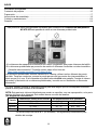
This Fireplace Glass Door is intended for surface mount installation on a masonry replace ONLY
DO NOT use this glass door on a pre-fabricated replace.
To determine the type of replace:
A. Masonry Fireplaces are constructed of brick and mortar with a brick chimney.
B. Pre-fabricated Fireplaces have a metal rebox and a sheet metal duct chimney.
Still not sure? Refer to our helpful video online at https://www.youtube.com/watch?v=CGJdgmoVLWY
A Pre-fabricated Fireplace, also called a Zero Clearance Fireplace, will require a different type of
Glass Door. While Fireplace Glass Doors appear interchangeable, they are not! If your replace is a
factory built pre-fab, Do Not use this rescreen. Check the make and model number of your
pre-fab replace and consult your dealer for the appropriate Fireplace Glass Door.
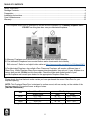
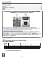
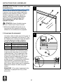
Please check the chart below to make certain you have purchased the correct Glass Door for your
replace opening.
*Height includes a 2” riser bar (not assembled). See assembly instructions for details.
Size Overal Door Dimension Fits Openings
Width x Height Width Height
Small 37.5” x 30” * 30” - 37” 22.5” - 29.5” *
Medium 37.5 x 33” * 30” - 37” 25.5” - 32.5” *
Large 43.5 x 33” * 36” - 43” 25.5” - 32.5” *
NOTE: This Fireplace Glass Door is designed to surface mount, with an overlap, on the outside of the
replace opening. This unit will cover a range of sizes.
(See the Chart below.)
TABLE OF CONTENTS
Safety Information ......................................................................................................................................3
Package Contents ......................................................................................................................................4
Preparation .................................................................................................................................................5
Installation Instructions ...............................................................................................................................6
Care & Maintenance .................................................................................................................................12
Warranty ...................................................................................................................................................12

3
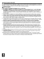
SAFETY INFORMATION
Please read and understand this entire manual before attempting to assemble, operate or install the
product. If you have any questions regarding the product, please call customer service at 1-877-447-4768,
8:00 a.m. – 4:30 p.m., CST, Monday – Friday.
1. NEVER LEAVE YOUR FIREPLACE UNATTENDED WHILE IT IS IN USE.
2. NEVER CLOSE THE FIREPLACE GLASS DOORS WHILE A FIRE IS BURNING IN THE
FIREPLACE. Excessive replace temperatures may result which could cause the glass doors to
shatter and cause personal injuries or property damage. Tempered glass does not imply unbreakable
glass. In the unlikely event of glass failure, it will shatter into small pieces to reduce the risk of
personal injury or property damage.
3. Always keep the wire mesh screen completely closed when the replace is in use, except when
adding wood. A closed screen acts as a safety barrier for sparks.
4. Always conrm that the chimney damper is open before starting a re and during use so that smoke
will not exhaust into the room. Always use the damper control knob(s) located at the bottom of the
rescreen to adjust the draft and re intensity.
5. Always position the rewood grate close to the back wall of the rebox and at least 7” back from the
wire mesh screen. Never build too large of a re, to assure safe use of the replace. Always keep all
combustible materials at least 3’ from the front of the replace when in use.
6. Never put any volatile substance in the replace. Always conrm that volatile liquids such as gasoline,
charcoal starter, lighter uid, lantern fuel, or kerosene are NOT located near the front of the replace.
Only use kindling or prepackaged re starter materials to start a re.
7. Always provide adult supervision for children and pets when the replace is in use, and keep them at
a safe distance to prevent accidental burns. To prevent burns, always wear an insulated mitt before
touching the damper control knobs, door handles, wire mesh screen, glass doors, or door frames
whenever the replace is in use.
8. Never use the replace for incinerating trash, newspapers, or waste materials which may release
toxic/noxious fumes.
9. Never allow cold water or other cold substances to come in contact with the replace doors before
they have cooled completely, as the glass could shatter.
10. Never attempt to dispose of ashes until they have cooled completely, as hot ashes are a potential
source of ignition. Always use the replace clean-out door (if available) for removing the ashes and
always use a metal container for safe disposal.
WARNINGS

4
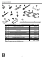
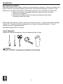
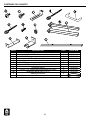
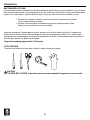
PART DESCRIPTION QTY. PART NO.
A 1/4-20 X 1/4” Machine Screw 2 10-09-115
B 1/4-20 X 1/2” Thread Cutting Screw 2 10-09-116
C 1/4-20 X 2” Thumbscrew (for lintel clamp) 2 10-09-117
D Lintel Clamp 2 10-04-122
E Key Bracket 2 10-04-123
F8-32 x 5/8” Machine Screw (only for Riser Bar) 2 10-09-118
G8-32 Hex Nut (only for Riser Bar) 2 10-09-119
H Pressure Bracket 2 10-04-124
I 1/4-20 X 3 1/2” Thumbscrew (for pressure bracket) 2 10-09-120
J&K Fiberglass Insulation (2” & 3” wide) 1 Bag 10-06-100
L Handles with Screws 2
M Riser Bar 1
PACKAGE CONTENTS
Some parts and specifications may change without notice.

5
PREPARATION
NEUTRALIZE THE HEARTH:
Newly-built replaces often contain a residue of acid used during construction. If allowed to remain in the
pores of the brick, this acid will release a gas that rusts iron and creates pitmarks or red spots. If your
builder has not neutralized the replace, follow these instructions prior to installing your Glass Door:
1. Brush a mild solution of household ammonia on all brick, stone, or cement
surfaces in your replace.
2. Remove all neutralizing solution by rinsing thoroughly with warm water,
followed by several cool rinses.
Before beginning assembly of product, make sure all parts are present. Compare parts with the package
contents list. If any part is missing or damaged, do not attempt to assemble the product. Contact
customer service for replacement parts.
Estimated Assembly Time: 60 minutes
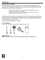
TOOLS REQUIRED:
Phillips and Flathead Screwdrivers, Scissors, Measuring Tape, Gloves
CAUTION
THIS UNIT IS HEAVY. Two people are required for safe assembly.

6
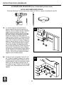
INSTALLATION INSTRUCTIONS
Carefully remove all contents from the carton
and place the Fireplace Glass Door on a at,
padded surface to avoid damaging the nish.
Always lift the door by the sides, not the top
frame. Check the included hardware against
the parts list.
If you are missing parts, please call GHP
customer service at 1-877-447-4768.
CAUTION: Before installing the Glass
Door, make sure the replace is cool.
STOP! Please refer to our installation video at:
https://www.youtube.com/watch?v=reR-LUvl62g
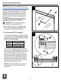
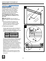
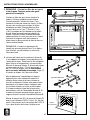
1. Mount door handles (L) to the glass doors
(left and right hand door assemblies) using
the screws provided with the handles.
2. This step may NOT be necessary!
The frame height (shown on Page 2) includes
a 2” riser bar. If your replace opening height
matches the dimensions noted below, DO NOT
ATTACH THE RISER BAR:
If the riser bar is required, lay the door face
down on a at, padded surface. Attach the riser
bar with two (2) 8-32 x 5/8” Machine Screws
(F) and two (2) Hex Nuts (G) as shown in
Figure 2. Use caution to protect your hands
from possible sharp metal edges. The back
edges of the riser bar and the back edges of
the bottom frame should be ush. In some
cases, the riser bar will extend in front of the
assembly frame which is correct.
NOTE: If your frame does not require a riser
bar, the screws (F) and nuts (G) may be
discarded.
1
2
Size Opening height
Small 27 3/4” or less
Medium 30 3/4” or less
Large 30 3/4” or less

7
INSTALLATION INSTRUCTIONS
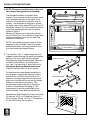
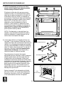
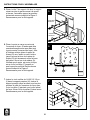
3. NOTE: Fiberglass insulation may irritate your
skin. Always wear gloves when handling.
The berglass insulation provided is heat
resistant. Your particular model may leave some
of the insulation exposed to the inside of the
replace. This is normal and should not be of
concern. This berglass is designed to protect
the metal nish of your frame. Both the 2” and 3”
Fiberglass Pieces (J & K) will separate into three
strips each by peeling them from one end as
shown in Figure 3.
Measure all dimensions of the back channels
on your Glass Door. Cut insulation to length with
scissors and place in back top and back side
channels as illustrated.
NOTE: The insulation does not need to ll the
channels to their full depth. Should you prefer
additional insulation, you may purchase it from
your local home improvement center.
4. The lintel bar is the “L” shaped angle iron that
supports the bricks along the top of the fireplace
opening. This bar is built into your masonry
fireplace when originally constructed. Measure
the width of the lintel bar. If the lintel bar is
less than 3” or more than 4” wide, refer to the
Alternative Mounting Method Instructions
(Page 8) and skip steps 4-6 in this section.
To determine the proper bracket assembly for
your replace, measure the distance from the
bottom of the Lintel Bar to the bottom of the
replace. Use this measurement to determine
where the Lintel Bar will line up with the slotted
brackets on the back of your frame. If the
measurement reaches the top of the slotted
brackets, follow Bracket Assembly A. If the
measurement is not the same height as the
slotted brackets, follow Bracket Assembly B.
Assemble the Key Bracket (E) to the lintel clamp
(D) with the 1/4-20 x 1/4” Machine Screw (A).
Do not tighten. Thread 1/4-20 x 2” Thumbscrew
(C) into lintel clamp. Do not tighten.
3” INSULATION
3” INSULATION
3” INSULATION
2” INSULATION
2” INSULATION
2” insulation needed here only if riser is required.
Bracket Assembly A
Lintel Bar
Bracket Assembly B
3
4

8
INSTALLATION INSTRUCTIONS
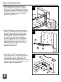
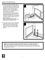
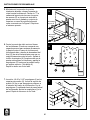
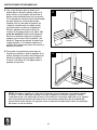
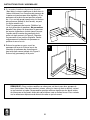
5. While keeping the door panels fully open,
place the Glass Door against the replace.
Place the “T” head of the Key Bracket (E) into
the slotted bracket on the back of the door as
shown in the inset and turn bracket assembly
to horizontal position as shown in Figure 5.
Repeat on opposite end.
6. Center the Glass Door against the replace
opening. (A second person may be necessary
to hold the door tightly against the replace
opening.) Reach inside and slide the Lintel
Clamp (D) back or forward until the lip of
the Lintel Clamp (D) is rmly against the
lintel bar. Tighten the 1/4-20 x 1/4” Machine
Screw (A). Making sure the Glass Door is
against the replace, tighten the 1/4-20 x 2”
Thumbscrew (C) until the door is secure on
top as shown in Figure 6.
Repeat on opposite end.
7. Insert 1/4-20 x 3 1/2” Thumbscrew (I) into
Pressure Bracket (H). Insert Pressure Bracket
(H) into the pair of holes closest to the side
of the replace opening. Making sure the
Thumbscrew (I) is pointing towards the sidewall
of the replace, tighten the Thumbscrew (I) into
the wall. Repeat on opposite end.
Bracket
Assembly A
Bracket
Assembly B
5
6
7

9
INSTALLATION INSTRUCTIONS
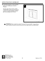
8. There are four door panel hinges (two in
the top track and two in the bottom track).
The door panel hinges are designed to be
adjusted. If the door panels are not evenly
aligned or if there is too much space
between the center of the door panels
(when they are in a closed position), you
may adjust them as follows:
Open the door panels. Reach inside and
loosen the panel hinge screws. Do not
remove the screws. Slide the door panel
hinges left or right until the space between
the center of the door panels is even, as
shown in Figure 8.
Return door panels to their original
position.Carefully maintain the door panel
hinge position and tighten screws.
9. To remove the door panels for cleaning or
replacement, begin by opening the door
panels. Remove the door panel hinge
screws from the top and bottom hinges
as shown in Figure 9. Remove the door
panel(s).
Door Hinge
Door Hinge
8
9
NOTE: In some models, a riser bar is provided with two sets of holes (top and bottom). For
proper flush fit, use the top or bottom set of holes, whichever are suitable to your frame.
Remember that proper flush means the back edges of the riser bar and the back edges of the
bottom frame assembly are even. In some cases, the riser bar will extend in front of the frame
assembly, which is correct.

10
INSTALLATION INSTRUCTIONS
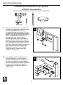
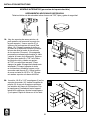
1A. There are two slotted brackets attached to
the back of the glass door frame (at the top).
Attach a Key Bracket (E) to each of
the slotted brackets as in Figure 1A. Place
the glass door against the replace opening,
center it, and mark the lintel bar through the
slots in the Key Brackets (2 places). (A
second person may be necessary to
hold the door tightly against the fireplace
opening.) Remove the glass door and drill a
7/32” hole at each location marked. (Wear
your safety glasses while drilling.) Place the
glass door against the replace opening and
align the holes with the slot in each Key
Bracket (E). Use 1/4-20 x 1/2” Thread
Cutting Screws (B) to attach both Key
Brackets to the lintel bar.
2A. Insert 1/4-20 x 3 1/2” Thumbscrew (I) into
Pressure Bracket (H). Insert Pressure
Bracket (H) into the pair of holes closest to
the side of the replace opening. Making
sure the Thumbscrew (I) is pointing towards
the sidewall of the replace, tighten the
Thumbscrew (I) into the wall. Repeat on
opposite end.
ALTERNATIVE MOUNTING METHOD (for top of glass door)
ADDITIONAL TOOLS REQUIRED:
Electric Drill, 7/32” High Speed Steel Bit, Pencil, and Safety Glasses
1A
2A

11
GHP Group, Inc.
6440 W. Howard St.
Niles, IL 60714-3302
877-447-4768 Made in the U.S.A.
INSTALLATION INSTRUCTIONS
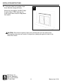
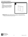
10. Once glass doors are installed, keep
them closed for energy efficiency.
When using the fireplace, ALWAYS keep
the glass doors OPEN, and keep the
screen mesh doors closed to help protect
from sparks.
10
CAUTION: Place rewood grate at least seven inches back from the mesh screen.
Discoloration may occur as a result of a large re or placing the grate too close to the
Glass Door frame.

12
CARE AND MAINTENANCE
ONE YEAR LIMITED WARRANTY
Cleaning the Glass:
Do not clean glass panels when they are hot! Cleaning the glass while it is hot may cause the glass to
break. Clean the glass with a mild solution of household ammonia and water. Do not use scouring pads,
glass wax, oil based cleaners, or scrapers. If you wish to remove the doors for cleaning, allow panels to
cool and follow the instructions for “Removing the Glass Doors”.
Cleaning the Metal Frame and Trim:
Do not use solvent, paint thinner, or abrasive cleaners. The metal frame and trim are powder coated to
resist tarnishing from the heat. Discoloration may occur as a result of large res or by having the wood
grate too close to the doors. Fingerprints or light marks on the frame are easily removed using rubbing
alcohol and a dry, smooth cloth.
ONE YEAR LIMITED WARRANTY
If within one year from the date of original purchase, this item fails due to a defect in material or
workmanship, we will replace or repair at our option, free of charge. To order parts or to obtain warranty
service, call 1-877-447-4768, Monday - Friday, 8:00 a.m. - 4:30 p.m. CST. This warranty does not cover
defects resulting from improper or abnormal use, misuse, accident, or alteration. Failure to follow all
instructions in the owner’s manual will also void this warranty. GHP Group, Inc. will not be liable for
incidental or consequential damages. Some states do not allow the exclusion or limitation of incidental
or consequential damages, so the above limitation or exclusion of incidental or consequential damages
may not apply to you. This warranty gives you specic legal rights and you may also have other rights
which vary from state to state.
GHP Group, Inc. • 6440 W. Howard St. • Niles, IL 60714-3302 • www.ghpgroupinc.com

¡ADVERTENCIA!
¡Nunca se cierran las chimenea puertas de vidrio, mientras que el fuego está ardiendo en la
chimenea!
Las temperaturas excesivas provenientes de la chimenea pueden ocasionar que se
rompan las puertas de vidrio ocasionando lesiones corporales o daños materiales.
REV. 08/18/2021
Chimenea Puerta de Vidrio
Français p. 25
English p. 1
ADVERTENCIA: Lea cuidadosamente todo el manual antes de empezar la instalacion de
su puerta de vidrio.
10-10-101
¿Preguntas, problemas, piezas faltantes? Antes de volver a la tienda, llame a nuestro
departamento de servicio al cliente al 1-877-447-4768, de lunes a viernes de 8:00 a.m. a
4:30 p.m., hora central estándar o envíenos un correo electrónico a
Manual del Propietario
No intente NUNCA usar la chimenea hasta que haya leído y comprendido las siguientes medidas
de seguridad, para evitar posibles daños tanto a usted como a su propiedad.
Por favor, consulte con su ciudad o código municipal antes de instalar esta chimenea puerta de vidrio.
CONSERVE ESTE MANUAL PARA FUTURAS REFERENCIAS
MODELO NÚM.: ______________ TAMAÑO: _______
NOMBRE MODELO: _________________
(Esta información aparece reejada en su resguardo de compra y/o etiqueta de la caja.)

14
Esta puerta de vidrio está destinada únicamente para instalación en chimenea de mampostería.
NO UTILICE esta pantalla de vidrio en una chimenea prefabricada.
To determine the type of replace:
A.La chimenea de mampostería construída con ladrillo y argamasa, que posee chimenea de ladrillo.
B.La chimenea prefabricada que posee tiro de metal con chimenea construída con tubería metálica.
¿Necesita más información? Consulte nuestro video útil en línea en:
https://www.youtube.com/watch?v=CGJdgmoVLWY
Una chimenea prefabricada, también llamada Zero Cleaning, utilizará un tipo diferente de puerta
de vidrio. Tenga en cuenta que, aunque le pueda parecer que las puertas son intercambiables, lo
cierto es que no lo son. Si su chimenea es prefabricada, no utilice esta pantalla. Consiga el número
de modelo y fabricación de su chimenea prefabricada y consulte con su distribuidor si desea más
información.
Por favor, tambien chequee el diagrama siguiente para estar seguro que Ud ha comprado la correcta
puerta de vidrio para el hueco de su chimenea.
*La altura incluye una barra de 2” (no montada), Vea siguientes procedimientos para
detalles del montaje.
NOTA: Esta puerta de vidrio está diseñada para montar en supercie, con una superposición, en la parte
exterior del hueco de la chimenea. Esta unidad abarca una serie de tamaños.
(Ver diagrama a continuación.)
INDICE
Informacion de seguridad .........................................................................................................................15
Contenido del paquete .............................................................................................................................16
Preparación ..............................................................................................................................................17
Instrucciones de ensamblaje ....................................................................................................................18
Cuidado y mantenimiento .........................................................................................................................24
Garantla ....................................................................................................................................................24
Tamaño Dimensiones Totales de las Puertas Se Adapta Abertura de la Chimenea
Anchura x Altura Anchura Altura
Pequeño 37.5” x 30” * 30” - 37” 22.5” - 29.5” *
Mediano 37.5 x 33” * 30” - 37” 25.5” - 32.5” *
Grande 43.5 x 33” * 36” - 43” 25.5” - 32.5” *

15
INFORMACION DE SEGURIDAD
Lea y comprenda completamente este manual antes de intentar ensamblar, usar o instalar el producto.
Si tiene preguntas relacionadas con el producto, lIame al Servicio al Cliente al: 1-877-447-4768, de
8:00 am a 4:30 pm, HEC, de lunes a viernes.
1. NO DEJE NUNCA DESATENDIDA LA CHIMENEA CUANDO ESTÉ EN FUNCIONAMIENTO.
2. NO CIERRE NUNCA LAS CHIMENEA PUERTAS DE VIDRIO MIENTRAS ESTÉ PRENDIENDO FUEGO LA
CHIMENEA. Las temperaturas excesivamente elevadas en la chimenea pueden provocar que estallen las
puertas de vidrio y dañen su persona o a su propiedad. Un vidrio templado no implica que sea irrompible. En el
caso poco probable de que fallase el vidrio, éste se romperá en diminutos trocitos para reducir el riesgo de daño
hacia su persona o a su propiedad.
3. Mantenga siempre cerrada completamente la malla o pantalla metálica cuando la chimenea se esté utilizando,
excepto cuando añada leña al fuego. La malla o pantalla, cuando está cerrada, actúa como protector para las
chispas.
4. Conrme siempre que el regulador de la chimenea se encuentre abierto antes de encender un fuego y cuando
esté funcionando la chimenea, para que el humo no escape al cuarto. Utilice siempre los botones de regulación
que se encuentran en la parte inferior de la chimenea para ajustar el nivel y la intensidad del fuego.
5. Posicione siempre la parrilla de la leña de modo que permanezca pegada a la parte posterior de la pared del tiro
de metal y al menos a 7” de la malla o cortina metálica. No haga nunca un fuego demasiado grande para una
utilización segura de su chimenea. Mantenga siempre todo material combustible al menos 3’ de distancia de la
chimenea cuando se esté utilizando.
6. No sitúe nunca ninguna sustancia volátil en la chimenea. Compruebe siempre no dejar nunca cualquier líquido
volátil cerca de la chimenea como gasolina, carbón vegetal, líquido encendedor, combustible de un farol o
querosene Solo utilice los materiales adecuados o aquellos que vengan empaquetados previamente para
encender el fuego.
7. Vigile siempre a los niños y a las mascotas cuando la chimenea esté funcionando y manténgalos a una
distancia segura para evitar que se quemen de manera accidental. Para prevenir quemaduras, póngase
siempre guantes aislantes (mitones) antes de manipular los botones de regulación, las manillas de la puerta, la
malla o pantalla metálica, las puertas de vidrio o los marcos cuando la chimenea esté funcionando.
8. No utilice nunca la chimenea para quemar basura, periódicos, o desperdicios, que puedan provocar gases
tóxicos.
9. No deje nunca que el agua fría u otras sustancias entren en contacto con las puertas de la chimenea antes de
que se hayan enfriado completamente ya que pudiese estallar el vidrio.
10. No intente nunca manipular las cenizas hasta que se hayan enfriado por completo, ya que las cenizas calientes
suponen una fuente potencial de ignición. Utilice siempre la puerta de limpieza (si está provista de ella) para
extraer las cenizas, para mayor seguridad emplee siempre un recipiente metálico.
ADVERTENCIA

16
CONTENIDO DEL PAQUETE
Algunas partes y especicaciones pueden cambiar sin previo aviso.
PIEZA DESCRIPCIÓN CANT. PIEZA NÚM.
A
1/4-20 X 1/4” Tornillo de máquina
2 10-09-115
B
1/4-20 X 1/2” Tornillo de rosca cortante
2 10-09-116
C
1/4-20 X 2” Empulgueras (para las abrazadera del dintel)
2 10-09-117
D
Abrazadera del dintel
2 10-04-122
E
Soporte
2 10-04-123
F
8-32 x 5/8” Tornillos de máquina (sólo para Montaje de barra)
2 10-09-118
G
8-32 Tuerca (sólo para montaje de barra)
2 10-09-119
H
Soporte de presión
2 10-04-124
I
1/4-20 X 3 1/2” Empulgueras (para soporte de Presion)
2 10-09-120
J&K
Aislante de bra de vidrio (3” & 2”)
1 Empaque
10-06-100
L
Manillas con tornillos
2
M
Barra
1

17
PREPARACIÓN
NEUTRALIZAR LA CHIMENEA:
Las chimeneas recién construidas contienen con frecuencia restos de ácido usados durante la
construcción. Si se permite que permanezcan en los poros del ladrillo, este ácido liberará un gas que
oxidará el hierro y dejará marcas o manchas rojas. Si su constructor no ha neutralizado la chimenea,
siga estas instrucciones antes de instalar la puerta.
1. Cepille con una solución suave de amoníaco todo el ladrillo, la piedra o las
supercies de cemento de su chimenea.
2. Limpie toda la solución neutralizante aclarando minuciosamente con agua
templada seguido de varios aclarados en frío.
Antes de comenzar a ensamblar el producto, asegúrese de tener todas las piezas. Compare las piezas
con la lista del contenido del paquete y los aditamentos anteriores. No intente ensamblar el producto si
falta alguna pieza o si éstas están dañadas. Póngase en contacto con el Departamento de Servicio al
Cliente para obtener piezas de repuesto.
Tiempo estimado de ensamblaje: 60 minutos
TOOLS REQUIRED:
Phillips and Flathead Screwdrivers, Scissors, Measuring Tape, Gloves
PRECAUCION
ESTA UNIDAD ES PESADA. Se necesitan dos personas para un ensamblaje seguro.

18
INSTRUCCIONES DE ENSAMBLAJE
Extraiga el contenido de la caja y sitúe la
pantalla de vidrio en una supercie plana
y acolchada para evitar que se dañe el
acabado. Agarre siempre la pantalla por
los lados, nunca por el marco superior.
Compruebe que tiene todos los cables y
dispositivos electrónicos de la lista.
Si le faltase alguno de ellos, por favor
llame a GHP Servicio al Cliente al 1-877-
447-4768.
PRECAUCION: Antes de instalar la
pantalla, asegúrese de que la chimenea está
fría.
¡DETÉNGASE! Consulte nuestro vídeo de
instalación en:
https://www.youtube.com/
watch?v=reR-LUvl62g
1. Monte las manillas de la puerta (L) en
las puertas de vidrio (montaje del lado
izquierdo y derecho) usando los tornillos
que se proveen junto con las manilas.
2. Puede no ser necesario!
La altura real del marco (que se muestra en
la página 20) incluye un barra de 2”. Si el
hueco de su chimenea alcanza las siguientes
medidas, NO INSTALE LA BARRA:
Cuando se precise la barra, coloque la puerta
boca abajo en supercie plana y acolchada.
Ajuste la barra con dos (2) tornillos de
máquina (F) 8-32 x 5/8” y dos (2) tuercas
hexagonales(G) (ver dibujo 2). Tenga cuidado
de no dañarse las manos con los bordes
metálicos. Los bordes de atras de la barra
y los bordes de atrás de la base del marco
podrian nivelarse. En algunos casos la barra
sobresaldra frente al ensamblaje del marco, lo
que es normal.
NOTA: Si no es necesaria la barra, puede
desechar los tornillos de máquina (F) y las
tuercas (G).
1
2
Tamaño Altura de Hueco
Pequeño 27 3/4” o menor
Mediano 30 3/4” o menor
Grande 30 3/4” o menor

19
Lintel
(vea más abajo)
4
INSTRUCCIONES DE ENSAMBLAJE
3. NOTE: El aislamiento de la bra de vidrio
puede irritarle la piel.Lleve siempre guantes
cuando maneje la bra de vidrio.
El aislante de bra de vidrio que se prove es
resistente al calor. Su modelo particular puede
dejar algo de aislante expuesto en el interior de
la chimenea. Esto es normal y no deberÍa ser
preocupacion. Esta bra de vidrio está diseñada
para proteger el acabado metálico de su marco.
Ambos el 3” y 2” bra de vidrio (J y K) se
separará en tres tiras pelando uno de los
extremos. (Vea el dibujo 3). Medida de todas
las dimensiones de los canales de vuelta en su
puerta de vidrio. Corte el aislante a medida con
unas tijeras y colóquelo en los canales de la
parte superior trasera y lateral.
NOTA: El aislamiento no necesita llenar los
canales a su profundidad completa.Si preere
adicional aislamiento, puede comprarlo de su
centro casero de mejoras del hogar.
4. La barra para dintel es el ángulo de hierro con
forma de “L” que sostiene el ladrillo por la parte
superior del hueco de la chimenea. Esta barra se
montó en su chimenea de mampostería cuando
ésta fue construida.Mida el ancho de la barra de
dintel. Si la barra tiene menos de 3” o más de 4”
de ancho, consulte el apartado Instrucciones
Alternativas de Montaje (Vea Página 26) y
sáltese los pasos 4-6 de esta seccion.
Para determinar el conjunto de soporte
ap2ropiado para su chimenea, medir la distancia
desde la parte inferior de la barra de dintel en
la parte inferior de la chimenea. Utilizar esta
medida para determinar dónde está el Bar dintel
se alinean con los soportes de ranura en la parte
posterior de su marco. Si la medida llega a la
parte superior de los soportes ranurados, siga
Ensamblaje soporte A. Si la medida no es la
misma altura que los soportes ranurados, siga
Montaje del soporte de B.
Ajuste el soporte E) a la abrazadera del dintel
(D) con el 1/4-20 x 1/4” tornillo de máquina (A).
No apriete. Atornille la 1/4-20 x 2” empulguera
(C) a la abrazadera del dintel. No apriete.
AISLAMIENTO 3”
AISLAMIENTO 3”
AISLAMIENTO 3”
AISLAMIENTO 2”
AISLAMIENTO 2”
El aislamiento no necesita sin barra.
3
Ensamblaje Soporte A
Ensamblaje Soporte B

20
INSTRUCCIONES DE ENSAMBLAJE
5. Manteniendo los paneles de puertas
totalmente abiertas, coloque la puerta de
cristal contra la chimenea. Colocar la “T” la
cabeza del soporte de clave en el soporte
de ranuras (E) en la parte de atrás de la
puerta como en el grabado y conjunto de
soporte a su vez a la posición horizontal
como se muestra en la Figura 5. Repita en
el extremo opuesto.
6. Centre la puerta de vidrio contra el hueco
de la chimenea. (Puede ser necesaria una
segunda persona para sostener rmemente
la puerta contra el hueco de la chimenea).
Introdúzcala bien y deslice la abrazadera del
lintel (D) de atrás hacia delante para que se
sujete rmemente contra la barra. Apriete el
tornillo de máquina (A). Asegúrese de que la
puerta está sujeta a la chimenea y apriete la
empulguera (C) hasta que la pantalla se je
en la parte superior. (Vea dibujo 6).
Repita lo mismo en el otro lado.
7. Inserte la 1/4-20 x 3 1/2” empulguera (I) en los
soportes de presión (H). Inserte el soporte de
presión (H) en un par de agujeros próximos a
el extremo del hueco de la chimenea. Con la
empulguera (I) señalando hacia la pared lateral
de la chimenea. Apriete la empulguera (I) a la
pared. Repita lo mismo en el otro lado.
Ensamblaje
Soporte A
Ensamblaje
Soporte B
5
6
7
La page charge ...
La page charge ...
La page charge ...
La page charge ...
La page charge ...
La page charge ...
La page charge ...
La page charge ...
La page charge ...
La page charge ...
La page charge ...
La page charge ...
La page charge ...
La page charge ...
La page charge ...
La page charge ...
-
 1
1
-
 2
2
-
 3
3
-
 4
4
-
 5
5
-
 6
6
-
 7
7
-
 8
8
-
 9
9
-
 10
10
-
 11
11
-
 12
12
-
 13
13
-
 14
14
-
 15
15
-
 16
16
-
 17
17
-
 18
18
-
 19
19
-
 20
20
-
 21
21
-
 22
22
-
 23
23
-
 24
24
-
 25
25
-
 26
26
-
 27
27
-
 28
28
-
 29
29
-
 30
30
-
 31
31
-
 32
32
-
 33
33
-
 34
34
-
 35
35
-
 36
36


Pleasant Hearth AE-1700BB Le manuel du propriétaire
- Catégorie
- Cheminées
- Taper
- Le manuel du propriétaire