Elkron EL50RT/2PH-60 Guide d'installation
- Catégorie
- Éclairage de confort
- Taper
- Guide d'installation

1/28 EL50RT 2PH 60m
DS80EL14-001 LBT80364 IS1213-AA
Manuale di Installazione
Installer manual
Notices Installateur
EL50RT 2PH 60m
Barriere ad infrarossi da esterno
Infrared Outdoor barriers
Barrières extérieures à infrarouge
I GB
F

2/28 EL50RT 2PH 60m
INDICE - INDEX
1.0 DESCRIZIONE COMPONENTI ................................................................................................3
2.0 AVVERTENZE PER L'INSTALLAZIONE ..................................................................................3
3.0 CONNESSIONI.........................................................................................................................4
4.0 INSTALLAZIONE ......................................................................................................................5
5.0 REGOLAZIONE TEMPO DI INTERVENTO..............................................................................6
6.0 IMPOSTAZIONE FREQUENZE DI LAVORO ...........................................................................7
7.0 ALLINEAMENTO OTTICO E PROGRAMMAZIONE FUNZIONAMENTO................................8
8.0 RISOLUZIONE DEI PROBLEMI ...............................................................................................9
9.0 CARATTERISTICHE TECNICHE .............................................................................................10
10.0 DIMENSIONI...........................................................................................................................10
1.0 PARTS DESCRIPTION.............................................................................................................11
2.0 CAUTIONS ON INSTALLATION...............................................................................................11
3.0 WIRING.....................................................................................................................................12
4.0 INSTALLATIONS ......................................................................................................................13
5.0 RESPONSE TIME ADJUSTMENT............................................................................................14
6.0 BEAM FREQUENCY CHANGE................................................................................................15
7.0 ALIGNMENT AND OPERATION...............................................................................................15
8.0 TROUBLESHOOTING..............................................................................................................17
9.0 SPECIFICATIONS ....................................................................................................................18
10.0 DIMENSIONS .........................................................................................................................18
1.0 DESCRIPTION DES COMPOSANTS.......................................................................................19
2.0 AVERTISSEMENTS POUR L'INSTALLATION.........................................................................19
3.0 CONNEXIONS..........................................................................................................................20
4.0 INSTALLATION.........................................................................................................................21
5.0 REGLAGE DU TEMPS D'INTERVENTION..............................................................................21
6.0 CONFIGURATION DES FREQUENCES DE TRAVAIL............................................................23
7.0 ALIGNMENT OPTIQUE ET PROGRAMMATION.....................................................................23
8.0 GUIDE DE DEPANNAGE .........................................................................................................25
9.0 CARACTERISTIQUES TECHNIQUES.....................................................................................26
10.0 DIMENSIONS .........................................................................................................................26

3/28 EL50RT 2PH 60m
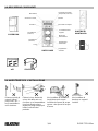
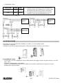
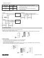
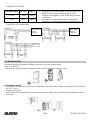
1.0 DESCRIZIONE COMPONENTI
COPERCHIO
2.0 AVVERTENZE PER L’INSTALLAZIONE
Rimuovere tutti gli
ostacoli (alberi,
panni stesi, etc..)
tra il trasmettitore
ed il ricevitore.
Evitare la luce diretta del
sole e fari delle auto sul
ricevitore e sul trasmettitore.
Una forte illuminazione
diretta per lungo tempo può
influire sulla vita del
prodotto.
Non installare la barriera in
luoghi dove può essere
investita da spruzzi di acqua
sporca o da spruzzi di acqua
di mare.
Non installare la
barriera su supporti
instabili.
Morsettiera
Selezione canale
Monitor +
Led ON OFF
(solo TX)
Led Allarme
(solo RX)
Lenti
Regolazione tempo
di risposta (solo RX)
Monitor
Microswitch Tamper
Led attenuazione
segnale
Mirino per
allineamento
Regolazione
orizzontale
Regolazione
verticale
UNITA' BASE
PIASTRA DI
MONTAGGIO
V
ITI STAFFE A U

4/28 EL50RT 2PH 60m
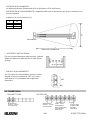
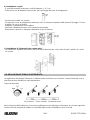
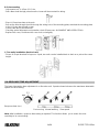
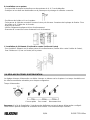
- DISTANZA DI RILEVAMENTO
La distanza massima di rilevamento è 60 m all’esterno e 120 m all’interno.
- AMPIEZZA ZONA DI RILEVAMENTO L’ampiezza della zona di rilevamento può essere calcolata con la
formula seguente:
Ampiezza (A) = 0,03 x distanza (L)
L A
20m 0,6m
40m 1,2m
60m 1,8m
- ALTEZZA DI INSTALLAZIONE
Per una corretta rilevazione delle intrusioni, l’altezza
ideale di installazione della barriera è di 80-100cm
da terra.
- ANGOLO DI ALLINEAMENTO
Sia il ricevitore che il trasmettitore possono essere
regolati in senso orizzontale di ± 90° ed in senso
verticale di ± 10° per adattarsi alle esigenze di
rilevazione.
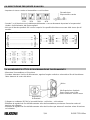
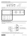
3.0 CONNESSIONI
- TRASMETTITORE
- RICEVITORE
Trasmettitore Ricevitore
Distanza di installazione
Alimentazione
10,5Vdc – 30 Vdc
non polarizzato
Alimentazione
10,5Vdc – 30 Vdc
non polarizzato Uscita Allarme
Relè contatto pulito
Uscita NC/NA
28Vdc/0,2A
Uscita Tamper
Contatto pulito
Uscita NC
28Vdc/0,2A
±10
±90

5/28 EL50RT 2PH 60m
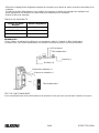
- LUNGHEZZA CAVO
TIPO CAVO 12Vdc 24Vdc
0.5 mm2 250m 2200m
1 mm2 440m 4000m
Note:
1. Quando 2 o più connessioni sono necessarie, la
massima distanza di collegamento è il valore come
da tabella a lato diviso per il numero di elementi
2. La lunghezza del cavo di alimentazione non può
superare i valori descritti nella tabella a lato
- ESEMPI DI COLLEGAMENTO
Esempio 1
Esempio 2
Esempio 3
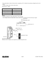
4.0 INSTALLAZIONE
La barriera può essere facilmente installata su un piano o su una superficie piana.
- Rimuovere il coperchio.
- Allentare la vite di bloccaggio della piastra e rimuoverla facendola scorrere contro la base.
A. Installazione a muro
- Far passare il cavo di collegamento nel foro della piastra di fissaggio e fissare la piastra al muro con le viti
(1/6 – x3/4-).
- Effettuare i collegamenti in morsettiera.
- Dopo la verifica dell’allineamento e del corretto funzionamento, riposizionare il coperchio e fissare
saldamente la vite di chiusura.
Alimentazione
Segnale di
allarme
Alimentazione
Allarme
(
Ch1
)
Allarme
(
Ch2
)
Segnale di
allarme
Alimentazione

6/28 EL50RT 2PH 60m
B. Installazione su palo
- E’ possibile montare le barriere su pali di diametro 4 – 4,5 cm.
- Praticare un foro di diametro 8mm sul palo per il passaggio del cavo di collegamento.
- Posizionare le staffe a U sul palo.
- Far passare il cavo di collegamento attraverso il foro e attraverso l'apertura della piastra di fissaggio. Fissare
le staffe a U con le viti fornite.
- Effettuare i collegamenti in morsettiera.
- Verificare l'allineamento ottico ed il corretto funzionamento.
- Rimontare il coperchio e stringere saldamente la vite di chiusura.
C. Installazione di 2 elementi (retro contro retro)
- Per installare 2 elementi sullo stesso palo alla stessa altezza (retro contro retro) fissare 2 staffe a U a strati
su un palo.
5.0 REGOLAZIONE TEMPO DI INTERVENTO
La regolazione del tempo di intervento si effettua tramite un trimmer sul ricevitore. I tempi visualizzati sono le
velocità massime rilevabili per ogni impostazione.
Tempo di intervento
Corsa veloce Passo normale Movimento lento
Nota: al termine dell'installazione è necessario effettuare un test del tempo di intervento che è stato impostato.
Questa funzione permette di adattare la sensibilità della barriera all'ambiente che la circonda.

7/28 EL50RT 2PH 60m
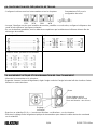
6.0 IMPOSTAZIONE FREQUENZE DI LAVORO
- Impostare lo stesso canale sul trasmettitore e sul ricevitore.
- Quando 2 o più barriere sono installate parallelamente o consecutivamente impostare la frequenza del
canale e fare riferimento alle figure seguenti.
- Nel caso di barriere parallele sia i sensori superiori che quelli inferiori devono essere dello stesso tipo di
modello.
Barriere parallele
Barriere consecutive
Protezione mista: parallele e consecutive
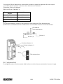
7.0 ALLINEAMENTO OTTICO E PROGRAMMAZIONE FUNZIONAMENTO
- Alimentare il trasmettitore ed il ricevitore.
- Guardare attraverso il mirino di allineamento, regolare l'angolo verticale e orizzontale al fine di visualizzare
l'altro elemento al centro del mirino.
- Collegare un voltmetro (DC10V) ai morsetti Monitor + e Monitor – sul ricevitore.
- Effettuare la regolazione fine dell'allineamento ottico del trasmettitore per ottenere il massimo valore di
tensione sul voltmetro.
- Effettuare la regolazione fine dell'allineamento ottico del ricevitore per ottenere il massimo valore di tensione
sul voltmetro.
Dip-switch per
l'im
p
ostazione canale
Mirino
Regolazione
Orizzontale
Vite Regolazione Verticale
Senso orario: verso l'alto
Senso antiorario: verso il basso

8/28 EL50RT 2PH 60m
- Posizionare il filtro di attenuazione sulle lenti del ricevitore e ripetere le regolazioni fini viste ai punti
precedenti al fine di ottenere il massimo valore di tensione sul voltmetro.
- Rimuovere il filtro ed il voltmetro.
TABELLA DELLA SENSIBILITA'
NOTE:
(1) I valori della tabella si riferiscono alle misurazioni fatte utilizzando il filtro di attenuazione.
(2) Rimuovere con attenzione il filtro di attenuazione e ricontrollare la tensione ai morsetti Monitor.
TEST FUNZIONAMENTO
E' consigliabile testare il funzionamento della barriera una volta al mese camminando in mezzo ai raggi.
Tensione al morsetto
Monitor Livello di allineamento
oltre 700 mV Ottimo
da 250 a 700 mV Buono
Minore di 250 mV Scarso
LED allarme
LED attenuazione
Monitor (-)
Monitor (+)
Filtro attenuazione
Puntale voltmetro (+)
Puntale voltmetro (-)
Ricevitore

9/28 EL50RT 2PH 60m
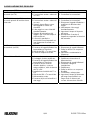
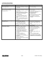
8.0 RISOLUZIONE DEI PROBLEMI
Difetto Causa Soluzione
Il LED di funzionamento non si
accende (sul TX) 1. Mancanza di alimentazione.
2. Connessione errata o rottura di
un cavo.
1. Alimentare la barriera.
2. Controllare le connessioni.
Il LED di allarme (sul RX) non si
accende quando la barriera viene
interrotta
1. Mancanza di alimentazione.
2. Connessione errata o rottura di
un cavo.
3. Il raggio viene riflesso su un
altro oggetto e inviato sul
ricevitore.
4. I due raggi non sono interrotti
simultaneamente.
5. Il tempo di interruzione del
raggio è più corto del tempo di
risposta del set.
6. I sensori in parallelo o
consecutivi sono impostati con
una frequenza di canale non
corretta.
1. Alimentare la barriera.
2. Controllare le connessioni.
3. Rimuovere l'oggetto riflettente o
modificare la direzione del
raggio.
4. Interrompere i due raggi
simultaneamente.
5. Impostare il tempo di risposta
più breve.
6. Reimpostare il canale di
frequenza seguendo le istruzioni
del manuale.
Il LED di allarme continua ad
accendersi (sul RX) 1. Allineamento mancante.
2. Presenza di oggetti riflettenti tra
trasmettitore e ricevitore.
3. Ottiche del RX o Tx macchiate.
4. Canale di frequenza errato.
1. Controllare e riallineare.
2. Rimuovere gli oggetti riflettenti.
3. Pulire le ottiche con un panno
morbido.
4. Impostare correttamente le
frequenze.
Allarmi intermittenti 1. Connessione errata.
2. Il voltaggio è stato modificato.
3. Presenza di oggetti riflettenti tra
trasmettitore e ricevitore.
4. Presenza di una fonte di
disturbo elettrico, come un
motore elettrico, nelle vicinanze
del TX e RX.
5. Installazione instabile del TX e
RX.
6. Ottiche del RX o Tx macchiate.
7. Allineamento errato.
8. Presenza di piccoli animali tra i
due raggi.
1. Ricontrollare.
2. Stabilizzare la tensione di
Alimentazione.
3. Rimuovere gli oggetti riflettenti
4. Cambiare il luogo di
installazione.
5. Stabilizzare.
6. Pulire le ottiche con un panno
Morbido.
7. Controllare e reimpostare.
8. Impostare il tempo di intervento
più lungo (impossibile in un
luogo dove un intruso può
correre alla massima velocità.

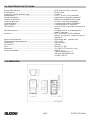
10/28 EL50RT 2PH 60m
9.0 CARATTERISTICHE TECNICHE
Portata della barriera:..........................................................................60 m (esterno), 120 m (interno)
Assorbimento:.....................................................................................85 mA (max)
Frequenza selezionabile dei raggi: ....................................................4 canali
Alimentazione:.....................................................................................10.5V - 30 VDC (non polarizzato)
Cellula fotoelettrica: ............................................................................raggi infrarossi doppia modulazione
Sistema di rilevazione: .......................................................................interruzione simultanea dei 2 raggi
Tempo di intervento: ..........................................................................50 msec - 700 msec (regolabile)
Uscita di allarme: ................................................................................Contatto pulito NC/NA 0,2A/28VDC
Uscita Tamper:....................................................................................Contatto pulito NC 0,2A/28VDC
LED allarme: .......................................................................................Led rosso (RX) si accende in presenza di
allarme
LED attenuazione:...............................................................................Led giallo (RX) si accende quando il
raggio è attenuato
Funzioni:..............................................................................................RF- Jack monitor, Uscita voltmetro
Monitor, circuito AGC, coperchio a prova
di ghiaccio
Angolo di allineamento: ......................................................................Orizzontale ±90° , verticale ±10°
Temperatura di funzionamento:..........................................................-25 a +55°C
Installazione: ......................................................................................esterno/interno
Connessioni: ......................................................................................morsetti
Peso: ..................................................................................................924 gr (Tx e RX)
Dimensioni: ........................................................................................76 x 181,5 x 77,8 mm (l x h x p)
Accessori standard: ............................................................................Staffe a U x 2
Filtro di attenuazione x 1
Viti (4x20 autofilettanti) x 4
Viti (M4 x 20) x 4
10.0 DIMENSIONI

11/28 EL50RT 2PH 60m
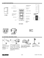
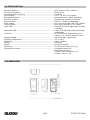
1.0 PARTS DESCRIPTION
COVER
2.0 CAUTIONS ON INSTALLATION
Remove all
obstructions (trees,
clothes lines, etc.)
Between
Transmitter and
Receiver.
Avoid strong light from the
sun, headlights, and direct
shining on the Transmitter /
Receiver. When strong light
stays in optical axis for
a long time, it will hurt the
product's lift.
Do not install the unit on
places where it may be
splashed by dirty water or
direct sea spray.
Do not install the
unit on the unsteady
place.
Terminals
Channel Set SW
Meter Jack
Monitor +
Operation LED
(Transmitter
only)
Alarm LED
Lens
Response Time
Adjustment
Meter Jack
Monitor -
Tamper Switch
Attenuation LED
View Finder
Horizontal
Adjustment
Vertical
Adjustment
Screw
UNIT BASE
MOUNTING
PLATE
HEATING
UNIT:
(OPTION)
SCREWS U-SHAPED
BRACKETS

12/28 EL50RT 2PH 60m
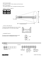
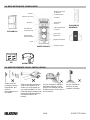
- DETECTION RANGE
Max detection range is 120m (outdoor) and 60m (indoor).
- DETECTION WIDTH
The detection width can be calculated with following formula :
Width (A) = 0,025 x Length (L)
L A
20m 0,6m
40m 1,2m
60m 1,8m
- INSTALLATION HEIGHT
To detect the intruder efficiently, the sensors should
be installed within 32"~40" (80~100cm) height.
- ALIGNMENT ANGLE
The sensors can be adjusted with Horizontal ± 90°
and Vertical ±10° to fit big detection range.
3.0 WIRING
- Transmitter
- Receiver
Transmitter Receiver
Protection distance
Power 10.5V to 30VDC
(non-polarity) Power
10.5V to 30VDC
(non-polarity) Alarm output
Dry connect relay
output NC./NO.
28VDC / 0.2A
Tamper output
Dry connect Micro
SW. Output NC.
28VDC / 0.2A
±10°
±90

13/28 EL50RT 2PH 60m
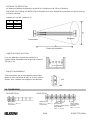
- WIRING DISTANCE
WIRE SIZE 12Vdc 24Vdc
0.5 mm2 250m 2200m
1 mm2 440m 4000m
Note:
1. When two or more connections is required,
maximum wiring distance is the value above divided
by the number of sets.
2. The power wires could not exceed the above
mentioned lengths.
- CONNECTION SAMPLE
Sample 1
Sample 2
Sample 3
4.0 INSTALLATIONS
The units can be mounted easily on a pole or flat surface.
- Remove cover via screw at base of cover.
- And loosen the unit base mounting screw and remove mounting plate by sliding it against the unit base.
A. Wall mounting
- Pull out the wire through the wiring hole on the mounting plate
and attach the plate to the wall with the screw ( 1/6ªx 3/4ª).
- Connect wire to the terminals.
- After checking optical alignment and operation check, ( please see 7.ALIGNMENT AND OPERATION )
replace the cover, and fasten the cover lock screw tightly.
Powe
r
Alarm signal
Powe
r
Alarm
(
Ch2
)
Alarm signal
Powe
r
Alarm
(
Ch3
)

14/28 EL50RT 2PH 60m
B. Pole mounting
- Unit mounts to a 4 -4,5cm O.D. Pole.
- Drill a 8mm hole through pole where the beam will be mounted for wiring.
- Place U-Shape brackets at the pole.
- Pull out the wire through the wire through the wiring hole of the mounting plate, attached the mounting plate
to the U-Shape bracket with screw.
- Connect the wire to the terminals.
- Checking optical alignment and operation check.(Please see ALIGNMENT AND OPERATION).
- Replace the cover, and fasten the cover lock screw tightly.
C. Two units installation (back to back)
- Fix two U-Shape brackets in layers on a pole, two units can be installed back to back on a pole at the same
height.
5.0 RESPONSE TIME ADJUSTMENT
The beam interruption time adjustment is on Receiver unit. Speeds shown below are the maximum detectable
speeds for each setting.
Response time (sec.)
Fast running Normal walking Slow speed
Note: After installation, response time testing is required. This function allows you to match the units
sensitivity to its surroundings.

15/28 EL50RT 2PH 60m
6.0 BEAM FREQUENCY CHANGE
- Set Transmitter and Receiver at the same channel.
- Refer to the figures and set the beam channel when two or more units are installed in stacked protection or in
line protection.
- When stacked protection is set up, both the upper and lower sensors should be the same model number
types.
stacked protection
Line protection
Line & 2-stacked protection
7.0 ALIGNMENT AND OPERATION
- Apply power to both Transmitter and Receiver.
- Looking through the view finder, locate the other detector in the center of the sights by adjusting vertically
and horizontally.
- Connect the volt-meter (DC10V) to monitor jack input on Receiver's (+) and (-).
- Fine adjust the optical alignment for Transmitter to obtain maximum voltage from the volt-meter.
- Fine adjust the optlcal alignment for Receiver to obtain maximum voltage from the volt-meter.
Channel Set
DIP-SW.
View Finder
Horizontal
Adjustment
Vertical adjustment screw
Screw clockwiseGUpward
CounterclockwiseGDownward

16/28 EL50RT 2PH 60m
- Place attenuation sheet on Receiver lens repeating 4 & 5 to obtain the maximum voltage from the volt-
meter.
- Taking off attenuation sheet, meter probe.
SENSITIVITY CHART
NOTE:
(1) Above readings is under attenuation sheet operation.
(2) Carefully remove the attenuation sheet, and check the voltage from the monitor jack again.
OPERATION CHECK
Monthly check is required, test operation by walk testing the beam
Monitor Jack Output Alignment Level
700 mV Over Best
250mV to 700 mV Good
250 mV Under Poor Realign
Alarm LED
Attenuation LED
Monitor jack (-)
Monitor jack (+)
Attenuation Sheet
Meter Probe (+)
Meter Probe (-)
Receiver

17/28 EL50RT 2PH 60m
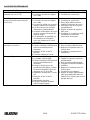
8.0 TROUBLESHOOTING
Trouble Check Corrective Action
Operation LED does not light.
( Transmitter Unit ) 1. No power supply.
2. Bad wiring connection or broken
wire, short.
1. Turn on the power.
2. Checking wiring.
Alarm LED does not light
when the beam is broken.
( Receiver Unit )
1. No power supply
2. Bad wiring connection or broken
wire, short.
3. Beam is reflected on another
object and sent into the receiver.
4. Two beams are not broken
simultaneously.
5. The beam interruption time is
shorter than the set response
time.
6. Inline or stacked beam sensors
set up with improper frequency
channel.
1. Turn on the power supply.
2. Check wiring.
3. Remove the reflecting object or
change beam direction.
4. Break two beams
simultaneously.
5. Set the response time shorter.
6. According to the manual
instruction and readjust the
channel.
Alarm LED continues to light
( Receiver Unit ) 1. Beam alignment is out.
2. Shading object between
Transmitter and Receiver.
3. Optics of units are soiled.
4. Wrong beam frequency channel
set up.
1. Check and adjust again.
2. Remove the shading object.
3. Clean the optics with a soft
cloth.
4. Readjust the DIP-SW for the
right channel.
Intermittent alarms 1. Bad wiring connection.
2. Change of supply voltage.
3. Shading object between
Transmitter and Receiver.
4. A large electric noise source,
such as power machine, is
located nearby Transmitter and
Receiver.
5. Unstable installation of
Transmitter and Receiver.
6. Soiled optics of Transmitter and
Receiver.
7. Improper alignment.
8. Small animals may pass through
the 2 beams.
1. Check again.
2. Stabilize supply voltage.
3. Remove the shading object.
4. Change the place for
installation.
5. Stablize.
6. Clean the optics with a soft
cloth.
7. Check and adjust again.
8. Set the response time longer.
(Impossible in a site where an
intruder can run at full speed. )

18/28 EL50RT 2PH 60m
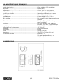
9.0 SPECIFICATIONS
Detection distance:..............................................................................60 m (outdoor), 120 m (indoor)
Current Consumption:.........................................................................85 mA (max)
Selectable Beam Frequency...............................................................4 channel
Power supply:......................................................................................10.5V - 30 VDC (non polarity)
Infrared photoelectric .........................................................................led pulsed beams, double modulation
Detection systems: .............................................................................Simultaneous breaking of 2 beams
Response time ...................................................................................50msec ~ 700msec ( Adjustable )
Alarm output: ......................................................................................Dry connect relay NC./ NO. 0.2A / 28VDC
Tamper output:....................................................................................Dry connect relay NC. 0.2A / 28VDC
Alarm LED:..........................................................................................Red LED (Receiver) lights when an alarm
is initiated.
Attenuation LED:.................................................................................Yellow LED (Receiver) lights when beam
is attenuated
Functions:............................................................................................RF-Monitor Jack, Meter Monitor Jack
output A.G.C. circuit, Frost proof cover.
Alignment Angle: ................................................................................Horizontal ±90°, Vertical ±10°
Operating Temperature:......................................................................-25° to +55°C
Installation: .........................................................................................Indoor / Outdoor
Wiring: ................................................................................................Terminals
Weight: ...............................................................................................924 gr (Tx and RX)
Dimensions: .......................................................................................76 x 181,5 x 77,8 mm (l x h x p)
Standard Accessories: .......................................................................U-Shaped brackets x 2
Attenuation Sheet x 1
Screws ( 4x20 Self tapping ) x 4
Screws ( M4 x 20 ) x 4
10.0 DIMENSIONS

19/28 EL50RT 2PH 60m
1.0 DESCRIPTION DES COMPOSANTS
COUVERCLE
2.0 AVERTISSEMENTS POUR L’INSTALLATION
Retirer tous les
obstacles (arbres,
linge tendu, etc.)
entre le
transmetteur et le
récepteur.
Éviter la lumière directe du
soleil et des phares de la
voiture sur le récepteur et
sur le transmetteur. Un fort
éclairage direct pendant une
longue période peut influer
sur la durée de vie du
produit.
Ne pas installer la barrière
dans des endroits où elle
puisse être atteinte par des
éclaboussures d’eau sale ou
d’eau marine.
Ne pas installer la
barrière sur des
supports instables.
Bornier
Sélection du canal
Moniteur +
DEL ON OFF
(seulement TX)
DEL d’alarme
(seulement RX)
Lents
Réglage du temps
de réponse
(seulement RX)
Moniteur -
Microswitch
Tamper
LED d’atténuation
du signal
Viseur pour
alignement
Réglage horizontal
Réglage vertical
UNITÉ DE BASE
PLAQUE DE
MONTAGE
VIS BRIDES EN U

20/28 EL50RT 2PH 60m
- DISTANCE DE DÉTECTION
La distance maximale de détection est de 60 m à l’extérieur et de 120 m à l’intérieur.
- AMPLEUR DE LA ZONE DE DÉTECTION L’ampleur de la zone de détection peut être calculée à l’aide de
la formule suivante :
Ampleur (A) = 0,025 x distance (L)
L A
20 m 0,6 m
40 m 1,2 m
60 m 1,8 m
- HAUTEUR D’INSTALLATION
Pour une détection correcte des intrusions, la
hauteur idéale d’installation de la barrière est de 80-
100 cm au sol.
- ANGLE D'ALIGNEMENT
Tant le récepteur que le transmetteur peuvent être
réglés en sens horizontal de ±90° et en sens vertical
de ±10° pour s’adapter aux exigences de détection.
3.0 CONNEXIONS
- TRASMETTEUR
- RÉCEPTEUR
Transmetteur Récepteur
Distance d’installation
Alimentation
10,5 V c.c. – 30 V c.c.
non polarisé
Alimentation
10,5 V c.c. – 30 V c.c.
non polarisé Sortie alarme
Relais de contact propre
Sortie NF/NO
28 V c.c. / 0,2 A
Sortie Tamper
Contact propre
Sortie NF
28 V c.c. / 0,2 A
±10
±90
La page est en cours de chargement...
La page est en cours de chargement...
La page est en cours de chargement...
La page est en cours de chargement...
La page est en cours de chargement...
La page est en cours de chargement...
La page est en cours de chargement...
La page est en cours de chargement...
-
 1
1
-
 2
2
-
 3
3
-
 4
4
-
 5
5
-
 6
6
-
 7
7
-
 8
8
-
 9
9
-
 10
10
-
 11
11
-
 12
12
-
 13
13
-
 14
14
-
 15
15
-
 16
16
-
 17
17
-
 18
18
-
 19
19
-
 20
20
-
 21
21
-
 22
22
-
 23
23
-
 24
24
-
 25
25
-
 26
26
-
 27
27
-
 28
28


Elkron EL50RT/2PH-60 Guide d'installation
- Catégorie
- Éclairage de confort
- Taper
- Guide d'installation
dans d''autres langues
Documents connexes


Autres documents
-
Nice Automation FE, FEP, FI and BF Le manuel du propriétaire
-
-
SICK L21 (L2000 sensor family) Mode d'emploi
-
-
-
KETRON SD1000 Le manuel du propriétaire
-
JCM NEOCELL Mode d'emploi
-
Nice F210B Le manuel du propriétaire
-
Telcoma FT201-Sincro Le manuel du propriétaire