
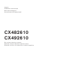
*DJJHQDX
Installation instructions2
Notice de montage14
Instrucciones de instalación27
CX482610
CX492610
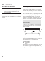
Full surface induction cooktop
Table de cuisson induction à pleine surface
Placa de cocción con inducción en toda la superficie

2
en-us Safety Definitions
Table of Contents
Installation instructions
Safety Definitions 2
IMPORTANT SAFETY INSTRUCTIONS 3
Safety Codes and Standards 3
Electric Safety 3
Related Equipment Safety 4
State of California Proposition 65 Warnings 4
Before you begin 5
Tools and parts needed 5
Parts included 5
Cabinet Requirements 5
Countertop Requirements 5
Prepare Installation Space 6
Flush Mounting 6
Cutout dimensions for 30" cooktops 6
Cutout dimensions for 36" cooktops 7
Combining several Vario devices 8
Ventilation 9
Installation Procedure 10
Installing the heat shield 10
Install Appliance 10
Removing appliance 11
Electrical Installation 11
Electrical requirements 11
Connect Electrical Supply 12
Check the Installation 12
Customer service 13
Safety Definitions
Safety Definitions
WARNING
This indicates that death or serious injuries may
occur as a result of non-observance of this warning.
CAUTION
This indicates that minor or moderate injuries may
occur as a result of non-observance of this warning.
NOTICE
This indicates that damage to the appliance or property
may occur as a result of non-compliance with this
advisory.
Note: This alerts you to important information and/or tips.

3
IMPORTANT SAFETY INSTRUCTIONS
READ AND SAVE THESE INSTRUCTIONS
IMPORTANT SAFETY INSTRUCTIONS
READ AND SAVE THESE INSTRUCTIONS
IMPORTANT: The appliance must be
installed by a qualified installer.
INSTALLER: please leave these
instructions with this unit for the owner.
Show the owner the location of the circuit
breaker or fuse. Mark it for easy
reference.
OWNER: Please retain these instructions
for future reference.
WARNING
If the information in this manual is
not followed exactly, fire or shock
may result causing property damage
or personal injury.
WARNING
Do not repair, replace or remove any
part of the appliance unless
specifically recommended in the
manuals. Improper installation,
service or maintenance can cause
injury or property damage. Refer to
this manual for guidance. All other
servicing should be done by an
authorized servicer.
Remove all tape and packaging before
using the appliance. Destroy the
packaging after unpacking the appliance.
Never allow children to play with
packaging material.
Hidden surfaces may have sharp edges.
Use caution when reaching behind or
under appliance.
This appliance is intended for use up to a
maximum height of 13,100 feet
(4,000 meters) above sea level.
Improper installation is not covered by
the warranty.
Safety Codes and Standards
This appliance complies with one or more
of the following Standards:
ʑ UL 858, The Standard for the Safety of
Household Electric Ranges
ʑ UL 507, The Standard for the Safety of
Electric Fans
ʑ CAN/CSA-C22.2 No. 113-M1984 Fans and
Ventilators
ʑ CAN/CSA-C22.2 No. 61-M89 Household
Cooking Ranges
It is the responsibility of the owner and
the installer to determine if additional
requirements and/or standards apply to
specific installations.
Electric Safety
WARNING
Before you plug in an electrical cord
or turn on power supply, make sure
all controls are in the OFF position.

IMPORTANT SAFETY INSTRUCTIONS
READ AND SAVE THESE INSTRUCTIONS
4
If required by the National Electrical
Code (or Canadian Electrical Code), this
appliance must be installed on a separate
branch circuit.
The circuit breaker should have a contact
separation of at least 3 mm on all poles.
Be sure your appliance is properly
installed and grounded by a qualified
technician. Installation, electrical
connections and grounding must comply
with all applicable codes.
Before installing, turn power OFF at the
service panel. Lock service panel to
prevent power from being turned ON
accidentally.
WARNING
IMPROPER GROUNDING CAN RESULT IN A
RISK OF ELECTRIC SHOCK!
Related Equipment Safety
The appliance should only be used if
installed by a qualified technician in
accordance with these installation
instructions. The manufacturer is not
responsible for any damage resulting
from incorrect installation.
Never modify or alter the construction of
the appliance. For example, do not
remove leveling legs, panels, wire covers
or anti-tip brackets/screws.
To eliminate the risk of burns or fire by
reaching over heated surface units,
cabinet storage space located above the
surface units should be avoided. If
cabinet storage is to be provided, the risk
can be reduced by installing a hood that
projects horizontally a minimum of 5
inches (127 mm) beyond the bottom of
the cabinet.
Verify that cabinets above the cooktop are
a maximum of 13" (330 mm) deep.
DO NOT install refrigerators,
dishwashers, ovens (without ventilation),
or washing machines below the Cooktop.
Note: We strongly recommend the
installation of a ventilation system with
this appliance.
State of California Proposition 65
Warnings:
WARNING
This product can expose you to
chemicals including vinyl chloride,
which is known to the State of
California to cause cancer and birth
defects or other reproductive harm.
For more information go to
www.P65Warnings.ca.gov.
Consult a qualified electrician if the
grounding instructions are not
completely understood, or if doubt
exists as to whether the appliance is
properly grounded. DO NOT USE AN
EXTENSION CORD.

5
Before you begin en-us
Before you begin
Before you begin
Tools and parts needed
ʑ Phillips Head Screwdriver
ʑ Pencil
ʑ Drill with ¼" (6 mm) bit
ʑ Jigsaw
ʑ Tape Measure
Note: Additional materials may be necessary for
installation in solid surface countertops. Contact the
countertop manufacturer.
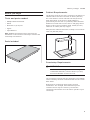
Parts included
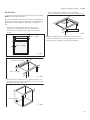
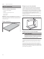
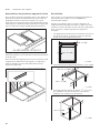
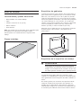
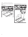
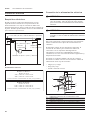
Cabinet Requirements
The distance from the top of the cooktop to the bottom of
cabinets above must be a minimum of A=30" (762 mm)
min. This distance can be reduced to A=24" (610 mm)
when the bottom of the wood or metal cabinet is
protected by not less than ¼" (6.35 mm) flame-retardant
millboard covered with not less than no. 28 gauge sheet
metal, 0.015" (0.4 mm) stainless steel, 0.024" (0.6 mm)
aluminum or 0.020" (0.5 mm) copper.
Verify that the cabinets above the cooktop are a maximum
of B=13" (330 mm) deep.
Countertop Requirements
WARNING
To reduce the risk of ignition of surrounding
combustible materials, install at least 2" (51 mm)
from both sidewalls and the rear wall.
The countertop must be level and horizontal. The stability
of the countertop must be maintained after the cut-out has
been made.
Solid surface countertops often require special
installations. For example, heat-reflective tape and
rounded corners may be necessary. Contact the
countertop manufacturer for instructions specific to your
countertop.
%
$

6
en-us Prepare Installation Space
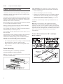
Prepare Installation Space
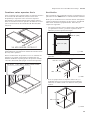
Prepare Installation Space
Create the cut-out in the countertop according to the
installation diagram. The angle of the cut surface to the
countertop must be 90°.
The lateral cut-out edges must be flat in order to ensure
that the retaining springs are positioned properly on the
appliance. With multi-layered countertops, secure strips
laterally in the cut-out if necessary.
After creating cut-out, remove shavings. Seal cut surfaces
in a heat- and water-resistant manner.
Observe minimum distance between device underside
and cabinet surfaces of
3
/
8
" (10 mm).
The worktop into which the cooktop is installed must be
heat-resistant up to 140° F (90 °C).
The worktop must be reinforced if it is less than
4
/
5
inch
(20 mm) thick.
If the thickness of the worktop into which the cooktop is
installed does not comply with the specifications,
reinforce the worktop using a fire- and water-resistant
material until it reaches the minimum thickness.
Otherwise, sufficient stability cannot be assured.
ʑ The worktop into which the cooktop is installed should
withstand loads of approx. 133 lbs (60 kg).
ʑ Only check the evenness of the cooktop after it has
been installed.
Flush Mounting
Flush mounting into a countertop is possible.
For flush installation in tiled countertops:
Note: If necessary, raise the support surfaces using heat
and water resistant strips.
Flush installation: The appliance can be installed in the
following temperature- and water-resistant countertops:
ʑ Stone countertops
ʑ Plastic countertops (such as Corian®)
ʑ Solid wood countertops: Only in consultation with the
manufacturer of the countertop (seal cut-out edges)
ʑ Installation in other countertops only in consultation
with the manufacturer of the countertop.
Installation in countertops made of particleboard is not
possible.
Note: Any cut-out work on the countertop must be
performed in a workshop according to the installation
diagram. The cut-out must be made cleanly and precisely
since the cut-out edge is visible on the surface. Clean and
degrease the cut-out edges with a suitable cleaning agent
(bear in mind silicone manufacturer's processing
instructions).
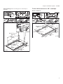
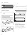
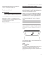
Cutout dimensions for 30" cooktops
Model: CX 482 610
PP
PLQ
PLQ
PP
PLQ
PLQ

7
Prepare Installation Space en-us
Flush mounting: Flush mounting into a countertop is
possible.
Cutout dimensions for 36" cooktops
Model: CX 492 610
PLQ
PP
PLQ
U
PLQ
PLQ
PLQ
PP
34
15/16
"
±1/16
PLQ
PLQ

8
en-us Prepare Installation Space
Flush mounting: Flush mounting into a countertop is
possible.
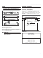
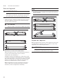
Combining several Vario devices
The connecting strip VA 420 000/001/010/011 is
required for the combination of several Vario appliances.
This is available separately as a special accessory.
Consider additional space requirement for the connecting
strip between the appliances when making the cut-out
(see installation instructions VA 420 000/001/010/011).
Appliances can also be installed in individual cut-outs,
bearing in mind a minimum distance between the devices
of 2" (51 mm).
When combining several appliances with or without
appliance cover, you can use the appliance extensions
VA 450 110/-401/-600/-800/-900 (depending on
appliance width) to balance out dimension differences.
PLQ
36"
34 15/16"
PP
PLQ
U
PLQ
9$
9$

9
Prepare Installation Space en-us
Ventilation
To assure that the appliance works correctly, the cooktop
MUST be sufficiently ventilated.
Since the ventilation in the lower section of the appliance
requires a sufficient supply of fresh air, the cabinet must
be designed accordingly. The following is required for
this:
ʑ A minimum clearance between the rear of the
cupboard and the kitchen wall, and between the
surface of the worktop and the upper area of the
drawer.
ʑ An opening at the top to the rear of the cupboard.
ʑ If the minimum clearance of
25
/
32
inch (20 mm) is not
provided at the rear of the cupboard, you must create
an opening on the underside.
ʑ If the inside of the cupboard is no wider than
29
1
/
2
inch (750 mm), make cutouts in the side panels.
Note: If the appliance is installed in an island unit or
another installation that is not described here, you must
ensure that the cooktop is sufficiently ventilated.
PLQæʌ¼ʕʔ
PLQ
PP
PLQë
PLQèè¼ʓʘ
PP
PLQæʌ¼ʕʔ
PP
$ê
PLQ
PP

10
en-us Installation Procedure
Installation Procedure
Installation Procedure
CAUTION
Sharp edges. Use protective gloves when installing
the cooktop.
Note: The appliance is heavy. It is advisable to install it
with a second person.
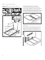
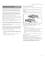
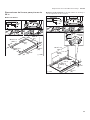
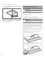
Installing the heat shield
CAUTION
Sharp edges. Use protective gloves when installing
the plate.
For safety reasons, the heat shield must be properly
installed when closed cabinets are used. This prevents
components from overheating as a result of the
recirculation of hot air from the cooktop.
The heat shield is the same width as the cooktop. For
shipping, it is screwed to the burner box.
After unpacking the cooktop, unscrew the heat shield.
The heat shield will be able to rotate freely, as shown in
the illustration.
Install Appliance
WARNING
Before you plug in an electrical cord or turn on
power supply, make sure all controls are in the OFF
position.
1. Evenly insert appliance into cut-out. Press appliance
firmly into the cut-out.
CAUTION
Do not kink or pinch connecting cable.
2. Only for flush installation:
Check appliance for functionality first (see section
“Check the installation").
Fill in the gap between the worktop and the ceramic
cooktop using a suitable heat-resistant silicone
adhesive (e.g. Novalsil® S70, Ottoseal® S70). Smooth
the sealing joint using the smoothing agent
recommended by the silicone manufacturer. Check the
usage information for the silicone adhesive.
Do not turn on the appliance until after the silicone
adhesive has completely dried (at least 24 hours,
depending on room temperature).

11
Installation Procedure en-us
NOTICE
Unsuitable silicone adhesive will cause natural stone
countertops to become permanently discolored.
Removing appliance
Disconnect the appliance from the power supply. For
flush-mounted appliances, remove the silicone joint. Push
out the appliance from below.
CAUTION
Damage to appliance! Don't lever device out from
above at the frame.
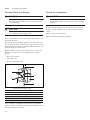
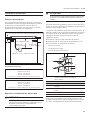
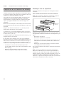
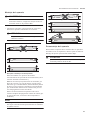
Electrical Installation
Electrical requirements
You can find the identification plate with the electrical
specifications on the underside of the appliance. The
junction box must be located within 3 feet of the cooktop
connection. It should be easily accessible for service
purposes.
Power supply
DSSUR[PP
&RQQHFWLRQ
Å-´%R[
PD[PP)LWWLQJ&RQGXLWPP
&RQGXLWDSSUR[IWaPP
PLQPP
DLUFOHDUDQFH
&;PRGHOV
$PSFLUFXLWEUHDNHU
9ROWV:LUH+]
9ROWV:LUH+]
$OOZLWKPIOH[LEOHFRQGXLWLQFOXGHG
&;PRGHOV
$PSFLUFXLWEUHDNHU
9ROWV:LUH+]
9ROWV:LUH+]
$OOZLWKPIOH[LEOHFRQGXLWLQFOXGHG

12
en-us Installation Procedure
Connect Electrical Supply
CAUTION
Before installing, turn off at the service panel. Lock
service panel to prevent power from being turned
on accidentally.
CAUTION
To reduce the risk of electric shock and fire, do not
use a flexible power supply cord.
Refer to data plate for more information. See "Service" for
data plate location.
The branch-circuit breakers ampacity, the wire sizes and
the connections must conform to the requirements of the
National Electrical Code or Canadian Electrical Code and
all local codes and ordinances.
Attach flexible conduit to the junction box. Connect the
lead wires to the junction box supply wires in proper
phase:
ʑ black (L1) to black
ʑ red (L2) to red
ʑ green or bare to ground
If the cooktop is installed and connected as specified
above, it will be completely grounded in compliance with
the National Electrical Code.
Check the Installation
CAUTION
Before you plug in an electrical cord or turn on
power supply, make sure all controls are in the OFF
position.
Remove everything from the cooktop surface including
stickers. Clean cooktop surface with cooktop cleaning
cream.
Switch on the circuit breaker.
Verify that elements function properly.
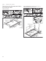
1 House power supply cord
2 Black wire
3 Junction box
4 Cooktop power supply cord
5 Grounded green or bare cable
6 Certified UL connector
7 Red wire

13
Customer service en-us
Customer service
Customer service
If your appliance needs repairs, our customer service is
there for you. We work hard to help solve problems
quickly and without unnecessary service calls, getting
your appliance back up and running correctly in the least
amount of time possible.
When you call, please indicate the product number (E-Nr.)
and serial number (FD-Nr.) so that we can support you in a
qualified manner. You will find the type plate with these
numbers on the bottom of the appliance. To avoid having
to search for a long time when you need it, you can enter
your appliance data and the customer support telephone
number here.
Please read the use and care instructions provided with
your appliance. Failure to do so may result in an error in
using the appliance. This could result in a service call
that instead of fixing a mechanical issue is only needed
for customer education. Such calls are not covered by the
appliance warranty.
Please find the contact data of all countries in the
enclosed customer service list.
To book an engineer visit and product advice
You can rely on the manufacturer’s expertise. Rest
assured that the repair will be handled by trained service
technicians who have the original replacement parts for
your appliance.
E-Nr. FD-Nr.
Customer Service 2
USA 877 442 4436
toll-free
CANADA 877 442 4436
toll-free

14
fr-ca Définitions de sécurité
Table des matières
Notice de montage
Définitions de sécurité 14
CONSIGNES DE SÉCURITÉ IMPORTANTES 15
Codes et normes de sécurité 15
Sécurité électrique 16
Équipement de sécurité 16
Avertissement issue de la proposition 65
de l’État de la Californie 17
Avant de commencer 18
Outils et pièces nécessaires 18
Pièces comprises 18
Exigences pour les placards 18
Exigences pour le plan de travail 18
Préparation des meubles 19
Pose en affleurement 19
Dimensions de la découpe pour tables
de cuisson de 30 po 20
Dimensions de la découpe pour tables
de cuisson de 36 po 21
Association de plusieurs appareils Vario 22
Ventilation 22
Procédure d'installation 23
Installation de l'écran pare-chaleur 23
Pose de l'appareil 24
Dépose de l'appareil 24
Installation électrique 25
Critères électriques 25
Brancher l'alimentation électrique 25
Vérification de l'installation 26
Service après-vente 26
Définitions de sécurité
Définitions de sécuri t é
AVERTISSEMENT
Ceci indique que le non-respect de cet
avertissement peut entraîner des blessures graves,
voire la mort.
ATTENTION
Ceci indique que le non-respect de cet
avertissement peut entraîner des blessures légères
ou de gravité moyenne.
AVIS
Ceci indique que la non-conformité à cet avis de sécurité
peut entraîner des dégâts matériels ou endommager
l'appareil.
Remarque : Ceci vous signale des informations et/ou
indications importantes.

15
CONSIGNES DE SÉCURITÉ IMPORTANTES
LIRE ET CONSERVER CES INSTRUCTIONS
CONSIGNES DE SÉCURITÉ IMPORTANTES
LIRE ET CONSERVER CES INSTRUCTIONS
IMPORTANT : L'électroménager doit être
installé par un installateur qualifié.
INSTALLATEUR : Laissez ces instructions
d’installation avec cet appareil à
l’intention du propriétaire. Montrez au
propriétaire l'emplacement du disjoncteur
ou du fusible. Identifiez sa position pour
pouvoir le retrouver facilement.
PROPRIÉTAIRE : Prière de conserver ces
instructions pour référence ultérieure.
AVERTISSEMENT
Si l’information de ce guide n’est
pas suivie exactement, il peut en
résulter un incendie ou un choc
électrique causant des dommages à
la propriété, des blessures ou la
mort.
AVERTISSEMENT
Ne réparez, remplacez, ni ne retirez
aucune partie de l'appareil, excepté
si les manuels recommandent de le
faire. Une installation, un entretien
ou une inspection incorrects peuvent
occasionner des blessures ou des
dommages matériels. Reportez-vous
au présent manuel pour obtenir des
indications. Toute autre intervention
doit être effectuée par un technicien
agréé.
Enlever le ruban adhésif et l’emballage
avant d’utiliser l’appareil. Détruire
l’emballage après avoir déballé l’appareil.
Ne jamais laisser les enfants jouer avec
les matériaux de conditionnement.
Certaines surfaces peuvent avoir des
bords tranchants. Faire attention en
étendant le bras derrière l’appareil ou en
dessous.
Cet appareil est conçu pour une
utilisation jusqu'à une altitude maximale
de 13 100 pieds (4 000 m).
La garantie ne couvre pas une mauvaise
installation.
Codes et normes de sécurité
Cet appareil est conforme à une ou
plusieurs des normes suivantes :
ʑ UL 858, norme pour la sécurité des
cuisinières électriques domestiques
ʑ UL 507, norme pour la sécurité des
ventilateurs électriques
ʑ CAN/CSA-C22.2 No. 113-M1984,
Ventilateurs et soufflantes
ʑ CAN/CSA-C22.2 No. 61-M89, Cuisinières
pour usage ménager
Il incombe au propriétaire et à
l'installateur de déterminer si des
exigences additionnelles et/ou normes
s'appliquent pour des installations
spécifiques.

CONSIGNES DE SÉCURITÉ IMPORTANTES
LIRE ET CONSERVER CES INSTRUCTIONS
16
Sécurité électrique
AVERTISSEMENT
Avant tout raccordement de cordon
électrique ou toute mise sous
tension, assurez-vous que toutes les
commandes sont en position OFF
(d'arrêt).
S'il y a lieu, conformément au Code
national de l'électricité (ou au Code
canadien de l'électricité), cet appareil
doit être installé sur un circuit de
dérivation séparé.
Le disjoncteur doit avoir une séparation
de contact de 3 mm. minimum pour tous
les pôles.
S'assurer que l'appareil est installé et mis
à la terre par un technicien qualifié.
L'installation, les connexions électriques
et la mise à la terre doivent être
conformes à tous les codes applicables.
Avant l'installation, mettre l'appareil hors
service au panneau de service.
Verrouiller le panneau d'entrée
d'électricité pour éviter que le courant ne
soit accidentellement rétabli.
AVERTISSEMENT
UNE MISE À LA TERRE INADÉQUATE PEUT
ENTRAÎNER UN RISQUE D'ÉLECTROCUTION !
Équipement de sécurité
Utilisez uniquement l’appareil
électroménager s’il a été installé par un
technicien qualifié conformément aux
présentes instructions d’installation. Le
fabricant ne peut pas être tenu
responsable de tous dommages causés
par une installation inadéquate.
Ne jamais modifier ni altérer la
configuration de l'appareil. Par exemple,
ne pas retirer les pieds de nivellement,
les panneaux, les couvercles de câblage
ou les fixations/vis antibasculement.
Pour éliminer le risque de brûlures ou
d’incendie lorsque l’on allonge le bras au-
dessus des éléments de surface chauds,
éviter d’installer des placards au-dessus
des éléments de surface. Si l’installation
de placards est prévue, le risque peut
être réduit en installant une hotte
aspirante qui dépasse horizontalement
d’au moins 5 po (127 mm) la base du
placard.
Consultez un électricien qualifié si
vous ne comprenez pas
parfaitement les instructions de
mise à la terre ou si vous avez des
doutes concernant une mise à la
terre appropriée. NE PAS UTILISER
DE RALLONGE.

17
CONSIGNES DE SÉCURITÉ IMPORTANTES
LIRE ET CONSERVER CES INSTRUCTIONS
Vérifiez que la profondeur des armoires
situées au-dessus de la table de cuisson
ne dépasse pas 13 po (330 mm).
La pose d'un appareil de réfrigération,
d'un lave-vaisselle, d'un four non ventilé
ou d'un lave-linge sous la table de
cuisson n'est pas autorisée.
Remarque : Nous recommandons
vivement l’installation d’un système de
ventilation avec cet appareil ménager.
Avertissement issue de la
proposition 65 de l’État de la
Californie :
AVERTISSEMENT
Ce produit peut vous exposer à des
produits chimiques, comme du
chlorure de vinyle, reconnus par
l’État de la Californie comme
causant le cancer, des malformations
congénitales ou d’autres effets
nocifs sur la reproduction. Pour de
plus amples renseignements,
consultez www.P65Warnings.ca.gov.

18
fr-ca Avant de commencer
Avant de commencer
Avant de commencer
Outils et pièces nécessaires
ʑ Tournevis à tête Philips
ʑ Crayon
ʑ Perceuse avec broche de 6 mm
ʑ Scie sauteuse
ʑ Mètre ruban
Remarque : Il faudra éventuellement avoir recours à
d’autres matériaux pour l’installation sur des surfaces de
travail solides. Prendre contact avec le fabricant de la
surface de travail.
Pièces comprises
Exigences pour les placards
La distance du haut de la table de cuisson au bas des
armoires au-dessus doit être au minimum de A=30 po
(762 mm). Cette distance peut être réduite à A=24 po
(610 mm) quand le bas de l'armoire en bois ou en métal
est protégé par du carton enroulé ignifuge d'un minimum
de ¼ po (6,35 mm), lequel est recouvert au minimum de
tôle de calibre 28, d'acier inoxydable de 0,015 po
(0,4 mm), d'aluminium de 0,024 po (0,6 mm) ou de cuivre
de 0,020 po (0,5 mm).
Vérifiez que la profondeur des armoires au-dessus de la
table de cuisson est au maximum de B=13 po (330 mm).
Exigences pour le plan de travail
AVERTISSEMENT
Pour réduire le risque d’inflammation des matériaux
combustibles adjacents, l’installation doit laisser un
dégagement d’au moins 2 po (51 mm) entre la table
de cuisson et les murs latéraux et arrière.
Le plan de travail doit être horizontal et plan. Veiller à la
stabilité du plan de travail, même après avoir creusé le
trou.
Certains plans de travail à haute résistance requièrent
souvent des aménagements spéciaux. Par exemple, une
bande thermoréfléchissante et des coins arrondis peuvent
être nécessaires. Contacter le fabricant du plan de travail
pour obtenir des précisions.
%
$

19
Préparation des meubles fr-ca
Préparation des meubles
Préparation des meubles
Réaliser la découpe pour l’appareil dans le plan de
travail, selon le schéma de pose. L'angle du chant de
coupe doit être de 90° par rapport au plan de travail.
Les bords de coupe latéraux doivent être plans afin de
garantir le positionnement correct des ressorts de
serrage sur l'appareil. Si le plan de travail est constitué
d'un matériau multicouche, fixer le cas échéant des
baguettes sur les côtés de la découpe.
Après les opérations de découpe, éliminer les copeaux.
Sceller les chants de coupe avec un produit assurant leur
résistance à la chaleur et l’humidité.
Respecter entre le dessous de l'appareil et les meubles
voisins une distance minimale de
3
/
8
" (10 mm).
Le plan de travail qui accueillera la table de cuisson doit
résister à des températures allant jusqu'à 90 °C (140° F).
Le plan de travail doit être renforcé si son épaisseur est
de moins de 20 mm (
4
/
5
po).
Si l'épaisseur du plan de travail qui accueillera la table de
cuisson ne respecte pas les spécifications, renforcez-le à
l'aide d'un matériau résistant à l'eau et au feu jusqu'à
atteindre l'épaisseur minimale. Sinon, vous pourriez ne
pas obtenir une stabilité adéquate.
ʑ Le plan de travail qui accueillera la table de cuisson
doit pouvoir résister à des charges d'environ 60 kg
(133 lb).
ʑ Vérifiez que la table de cuisson est de niveau
uniquement après son installation.
Pose en affleurement
L'appareil peut être posé en affleurement dans un plan de
travail.
Pour une installation affleurante dans des comptoirs avec
carrelage :
Remarque : Au besoin, soulevez les surfaces de soutien
à l'aide de bandes résistantes à la chaleur et à l'eau.
Pose en affleurement: L'appareil peut être encastré dans
des plans de travail résistant à la chaleur et à l'eau,
fabriqués dans les matériaux suivants :
ʑ pierre
ʑ matière plastique ou Corian®
ʑ bois massif : seulement avec l'accord avec le fabricant
du plan de travail (sceller les bords de coupe)
ʑ La pose dans d'autres types de plan de travail :
seulement avec l'accord avec le fabricant du plan de
travail.
La pose dans de plan de travail de panneaux de particules
n'est pas autorisée.
Remarque : Toutes les découpes du plan de travail
doivent être faits dans un atelier spécialisé,
conformément au schéma de pose. La découpe doit être
nette et précise, car le bord de coupe est visible en
surface. Nettoyer et dégraisser les bords de coupe avec
un produit de nettoyage adéquat (respecter les
instructions d'application du fabricant du silicone).
PP

20
fr-ca Préparation des meubles
Dimensions de la découpe pour tables
de cuisson de 30 po
Modèle: CX 482 610
Pose en affleurement: L'appareil peut être posé en
affleurement dans un plan de travail.
PLQ
PLQ
PP
PLQ
PLQ
PLQ
PP
PLQ
U
PLQ
La page est en cours de chargement...
La page est en cours de chargement...
La page est en cours de chargement...
La page est en cours de chargement...
La page est en cours de chargement...
La page est en cours de chargement...
La page est en cours de chargement...
La page est en cours de chargement...
La page est en cours de chargement...
La page est en cours de chargement...
La page est en cours de chargement...
La page est en cours de chargement...
La page est en cours de chargement...
La page est en cours de chargement...
La page est en cours de chargement...
La page est en cours de chargement...
La page est en cours de chargement...
La page est en cours de chargement...
La page est en cours de chargement...
La page est en cours de chargement...
-
 1
1
-
 2
2
-
 3
3
-
 4
4
-
 5
5
-
 6
6
-
 7
7
-
 8
8
-
 9
9
-
 10
10
-
 11
11
-
 12
12
-
 13
13
-
 14
14
-
 15
15
-
 16
16
-
 17
17
-
 18
18
-
 19
19
-
 20
20
-
 21
21
-
 22
22
-
 23
23
-
 24
24
-
 25
25
-
 26
26
-
 27
27
-
 28
28
-
 29
29
-
 30
30
-
 31
31
-
 32
32
-
 33
33
-
 34
34
-
 35
35
-
 36
36
-
 37
37
-
 38
38
-
 39
39
-
 40
40


dans d''autres langues
- English: Gaggenau CX492610 Installation guide
- español: Gaggenau CX492610 Guía de instalación
Documents connexes
-
Gaggenau VI 422 611 Guide d'installation
-
-
Gaggenau CI292601 Guide d'installation
-
-
Gaggenau CI282602 Guide d'installation
-
Gaggenau VI263 Guide d'installation
-
Gaggenau VI230 Guide d'installation
-
Gaggenau CX48261x Manuel utilisateur
-
-
Gaggenau VP 414 Guide d'installation
Autres documents
-
Bosch NIT5469UC Guide d'installation
-
Bosch NIT5068UC Guide d'installation
-
Bosch NITP668SUC Guide d'installation
-
-
Thermador CIT365TB Guide d'installation
-
Siemens PIP801N17V/01 Manuel utilisateur
-
Bosch Appliances NES 730 UC Manuel utilisateur
-
Cooke & Lewis Korlam Mode d'emploi