Kichler Lighting 44337DBK Manuel utilisateur
- Taper
- Manuel utilisateur

IS-44337-CB
We’re here to help 866-558-5706
Hrs: M-F 9am to 5pm EST
1) Take threaded pipe[A] from parts bag and screw in screw
on the hexnut[C] as shown.
2) Screw threaded pipe into mounng strap[B]. Mounng
strap must be posioned with extruded thread faced into
outlet box[E]. Threaded pipe must protrude out the back
of mounng strap.
3) Connect mounng strap to outlet box using the strap
mounng screws[D].
4) Grounding instrucons: (See Illus. a or b).
a) On xtures where mounng strap is provided with a
hole and two raised dimples, wrap ground wire from
outlet box around green ground screw, and thread
into hole.
b) On xtures where a cupped washer is provided,
aach ground wire from outlet box under cupped
washer and green ground screw, and thread into
mounng strap.
If xture is provided with ground wire, connect xture
ground wire to outlet box ground wire with wire
connector aer following the above steps. Never connect
ground wire to black or white power supply wires.
5) Make wire connecon. Reference chart below for correct
connecons and wire accordingly.
Connect Black or Red
Supply Wire to:
Connect White Supply
Wire to:
Black White
*Parallel cord (round &
smooth)
*Parallel cord (square &
ridged)
Clear, Brown, Gold or
Black without Tracer
Clear, Brown, Gold or Black
with Tracer
Insulated wire (other
than green) with copper
conductor
Insulated wire (other
than green) with silver
conductor
*Note: When parallel wire (SPT
1 & SPT 2) are used. The neutral
wire is square shaped or ridged
and the other wire will be round
in shape or smooth (see illus.)
Neutral Wire
6) Push xture to wall carefully passing threaded pipe with
holes in canopy. NOTE: xture can be mounted with glass
in the up or down posion. Make sure all wires are inside
canopy and do not get pinched between wall and canopy
of xture.
7) Place the lock washer[J] onto the threaded mounng
pipe and thread lockup knobs[K] onto mounng pipe
and ghten to secure xture to wall.
8) Raise the side glass panel[F] up to the side of the main
body and secure into place using four (4) screws[G] and
four (4) sloed nuts[H]. Repeat for the other side panels.
9) Raise the front glass panel[I] up to the front of the main
body and secure into place using four (4) screws[G] and
four (4) sloed nuts[H].
10) Insert recommended bulb. (Not supplied)
GREEN GROUND
SCREW
CUPPED
WASHER
OUTLET BOX
GROUND
FIXTURE
GROUND
DIMPLES
WIRE CONNECTOR
OUTLET BOX
GROUND
GREEN GROUND
SCREW
FIXTURE
GROUND
a
b
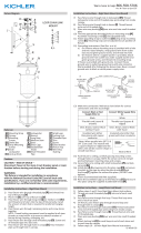
Fixture Diagram
Parts List
Cauons
CAUTION – RISK OF SHOCK –
Disconnect Power at the main circuit breaker panel or main
fusebox before starng and during the installaon.
WARNING:
This xture is intended for installaon in accordance
with the Naonal Electrical Code (NEC) and all local code
specicaons. If you are not familiar with code requirements,
installaon by a cered electrician is recommended.
Installaon Instrucons
[A] Threaded
Pipe
[B] Mounting
Strap
[C] Hexnut
[D] Strap
Mounting
Screws
[E] Outlet Box
[F] Side Glass
Panel
[G] Screws
[H] Slotted Nuts
[I] Front Glass
Panel
[J] Lock Washer
[K] Lockup Knobs
E
D
B
A
I
F
H
G
E
J
K
C

IS-44337-CB
Nous sommes là pour vous aider 866-558-5706
Heures : du lundi au vendredi, de 9h à 17h (heure de l’Est)
INSTRUCTIONS:
For Assembling and Installing Fixtures in Canada
Pour L’assemblage et L’installaon Au Canada
1) Sortez le tube leté [A] du sac de pièces et serrez-le avec
la vis sur l’écrou hexagonal [C] (voir illustraon).
2) Vissez maintenant le tube leté dans le support de
montage [B]. Le support de montage doit être placé avec
le let extrudé faisant face à la boîte à prises [E]. Le tube
leté doit sorr de l’arrière du support de montage.
3) Fixez le support de montage sur la boîte à prises avec les
vis de xaon du support [D].
4) Connecter les ls. Se reporter au tableau ci-dessous pour
faire les connexions.
Connecter le l noir ou
rouge de la boite
Connecter le l blanc de
la boîte
A Noir A Blanc
*Au cordon parallèle (rond
et lisse)
*Au cordon parallèle (à
angles droits el strié)
Au transparent, doré,
marron, ou noir sans l
disncf
Au transparent, doré,
marron, ou noir avec un l
disncf
Fil isolé (sauf l vert) avec
conducteur en cuivre
Fil isolé (sauf l vert) avec
conducteur en argent
*Remarque: Avec emploi d’un
l paralléle (SPT 1 et SPT 2). Le
l neutre est á angles droits ou
strié et l’autre l doit étre rond
ou lisse (Voir le schéma).
Fil Neutre
5) Poussez le luminaire vers le mur en passant
soigneusement le tube leté par le trou du couvercle.
REMARQUE : Le luminaire peut être monté avec le verre
en posion haute ou basse. S’assurer que tous les ls
sont à l’intérieur du couvercle et ne sont pas pincés entre
le mur et le couvercle du luminaire.
6) Placez la rondelle de blocage [J] sur le tube de montage
leté et vissez les boutons de blocage [K] sur le tube de
montage. Serrez pour xer le luminaire au mur.
7) Soulevez le panneau en verre latéral [F] sur le côté du
corps principal et xez-le à l’aide de quatre (4) vis [G] et
de quatre (4) écrous fendus [H]. Répétez l’opéraon pour
les autres panneaux latéraux.
8) Soulevez le panneau en verre avant [I] jusqu’à la pare
frontale du corps principal et xez-le à l’aide de quatre
(4) vis [G] et de quatre (4) écrous fendus [H].
9) Installez l’ampoule recommandée (non fournie).
Diagramme d’appareils
ATTENTION – RISQUE DE DÉCHARGES ÉLECTRIQUES -
Couper le courant au niveau du panneau du disjoncteur du
circuit principal ou de la boîte à fusibles principale avant de
procéder à l’installaon.
ATTENTION:
Ce luminaire doit être installé conformément aux codes
d’électricité naonaux (NEC) et sasfaire toutes les
spécicaons des codes locaux. Si vous ne connaissez pas
les exigences de ces codes, il est recommandé de coner
l’installaon à un électricien ceré.
Liste des Pièces
Précauons
Instrucons d’installaon
E
D
B
A
I
F
H
G
E
J
K
C
[A] Tube Fileté
[B] Support de
Montage
[C] Écrou
Hexagonal
[D] Vis de
Fixation du
Support
[E] Boîte à prises
[F] Panneau en
Verre Latéral
[G] Vis
[H] Écrous
Fendus
[I] Panneau en
Verre Avant
[J] Rondelle de
Blocage
[K] Boutons de
Blocage
-
 1
1
-
 2
2