Samsung NE59M7630SG/AC Manuel utilisateur
- Taper
- Manuel utilisateur

imagine the possibilities
Thank you for purchasing this Samsung product.
Electric Range
installation manual
Manual Installation_30 Oven_SECA_DG68-00109F-08_EN+CFR.indb 1 9/6/2018 6:52:48 PM

before you begin
ANTI-TIP DEVICE
WARNING: To reduce the risk of tipping the appliance, the appliance must be
secured by properly installed anti-tip devices packed with the appliance.
a) A child or adult can tip the range and be killed.
b) Install the anti-tip device to the structure and/or the range at rear right (or rear left)
of the range bottom.
c) Engage the range to the anti-tip device by leveling leg at rear right (or rear left) of
the range bottom.
d) Re-engage the anti-tip device if the range is moved.
e) See installation instructions for details.
f) Failure to do so can result in death or serious burns to children or adults.
ABOUT THIS MANUAL
READ THESE INSTRUCTIONS COMPLETELY AND CAREFULLY.
Important note to the installer
• Read all instructions contained in these installation instructions before installing range.
• Remove all packing materials from the oven compartments before connecting the electrical supply
to the range.
• Observe all governing codes and ordinances.
• Be sure to leave these instructions with the consumer.
Important note to the consumer
Keep these instructions for the local electrical inspector’s use.
• As when using any appliance generating heat, there are certain safety precautions you should follow.
• Be sure your range is installed and grounded properly by a qualified installer or service technician.
• Make sure the wall coverings around the range can withstand the heat generated by the range.
• To eliminate the need to reach over the surface elements, cabinet storage space above the elements
should be avoided.
• The range should not be placed on a base.
FOR YOUR SAFETY
WARNING
WARNING If the information in this manual is not followed exactly, a fire or electrical
shock may result causing property damage, personal injury or death.
WARNING
WARNING Before beginning the installation, switch power off at the service panel and
lock the service disconnecting means to prevent power from being switched on accidentally. When the
service disconnecting means cannot be locked, securely fasten a prominent warning device, such as a
tag, to the service panel.
WARNING
WARNING This appliance must be properly grounded.
WARNING
English - 2
Manual Installation_30 Oven_SECA_DG68-00109F-08_EN+CFR.indb 2 9/6/2018 6:52:48 PM

preparing to install the range
REMOVE PACKAGING
Remove packaging materials. Failure to remove packaging materials could result in damage to the
appliance.
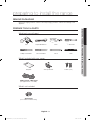
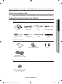
PREPARE TOOLS & PARTS
What tools you will need
Drill Adjustable Wrench Pliers
1
/4˝ Nut Driver
Phillips Screwdriver Flat Screwdriver Pencil Level
What’s included with your range
Template Anti-Tip Bracket Screws (4 ea)
4-Wire Cord or 3-Wire Cord
(UL Approved 40 or 50 AMP)
What’s not included
Strain Relief
(For Conduit Installation Only)
English - 3
01
BEFORE YOU BEGIN & PREPARING TO INSTALL THE RANGE
Manual Installation_30 Oven_SECA_DG68-00109F-08_EN+CFR.indb 3 9/6/2018 6:52:50 PM

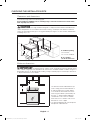
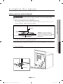
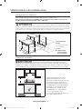
CHECKING THE INSTALLATION SITE
Clearances and dimensions
To install the range, refer to the following figure.
For installation in CANADA, a Free-standing range is not to be installed closer than 12mm
from any adjacent surface.
CAUTION
CAUTION This range has been designed to comply with the maximum allowable wood
cabinet temperatures of 194°F. Make sure the wall covering, countertops and cabinets around the
range can withstand the heat (up to 194°F) generated by the range. If not, discoloration, delamination
or melting may occur.
A
B
36" ~ 37"
46
1
/2
" ~ 47
1
/2
"
29
15
/16"
1
9
/16
"
24
7
/8"
7
1
/2"
24
1
/2"
26
1
/16"
49
3
/8"
28
7
/16"
29
7
/8"
6"
25"
3"
24"
3"
A : Cabinet opening
30” For U.S.A,
30”~31” For CANADA.
B : Acceptable
electrical outlet area
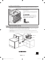
Minimum dimensions
IMPORTANT To eliminate the risk of burns or fire caused by reaching over heated surface
units, cabinet storage space located above the surface units should be avoided. If cabinet storage is to
be provided, the risk can be reduced by installing a range hood that projects horizontally a minimum of
5” beyond the bottom of the cabinets.
* 30”
30”
** 15”
* 30” minimum clearance between the top
of the cooking surface and the bottom of
an unprotected wood or metal cabinet;
or 24” minimum when the bottom of the
wood or metal cabinet is protected by not
less than
1
/4” flame retardant millboard
covered with not less than no.28 MSG
sheet steel, 0.015” stainless steel, 0.024”
aluminum or 0.020” copper.
** 15” minimum between the countertop and
the adjacent cabinet bottom.
English - 4
Manual Installation_30 Oven_SECA_DG68-00109F-08_EN+CFR.indb 4 9/6/2018 6:52:50 PM

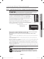
connecting the power
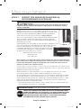
STEP 1. MEETING ELECTRICAL CONNECTION REQUIREMENTS
CAUTION
CAUTION For personal safety, do not use an extension cord with this appliance.
Remove house fuse or open circuit breaker before beginning installation.
This appliance must be supplied with the proper voltage and frequency, and
connected to an individual properly grounded branch circuit, protected by a
circuit breaker or fuse having amperage as specified on the rating plate. The
rating plate is located above the drawer on the oven frame. (Fig. 1 or Fig. 2)
We recommend you have the electrical wiring and hookup of your range
connected by a qualified electrician. After installation, have the electrician show
you where your main range disconnect is located.
Check with your local utilities for electrical codes which apply in your area.
Failure to wire your oven according to governing codes could result in a
hazardous condition. If there are no local codes, your range must be wired and
fused to meet the requirements of the National Electrical Code, ANSI/NFPA No.
70–Latest Edition. You can get a copy by writing:
National Fire Protection Association
Batterymarch Park
Quincy, MA 02269
Effective January 1, 1996, the National Electrical Code requires that new construction (not
existing) utilize a 4-conductor connection to an electric range.
When installing an electric range in new construction, follow Steps 2 and 3 for 4-wire
connection.
You must use a 3-wire or 4-wire, single-phase A.C. 208Y/120 Volt or 240/120 Volt, 60 hertz electrical
system.
If the electrical service provided does not meet the above specifications, have a licensed electrician
install an approved outlet.
Use only a 3-conductor or a 4-conductor UL-listed range cord. These cords may be provided with ring
terminals on wire and a strain relief device.
A range cord rated at 40 amps with 125/250 minimum volt range is required. A 50 amp range cord
is not recommended but if used, it should be marked for use with nominal 1
3
⁄8” diameter connection
openings. Care should be taken to center the cable and strain relief within the knockout hole to keep
the edge from damaging the cable.
• Because range terminals are not accessible after range is in position, flexible service conduit or cord
must be used.
NOTE If conduit is being used, go to Step 4 on page 9.
ALL NEW BRANCH-CIRCUIT CONSTRUCTIONS, MOBILE HOMES,
RECREATIONAL VEHICLES AND INSTALLATIONS WHERE LOCAL CODES DO
NOT ALLOW GROUNDING THROUGH NEUTRAL, REQUIRE A 4-CONDUCTOR
UL-LISTED RANGE CORD.
(Fig. 1)
(Fig. 2)
English - 5
02 CONNECTING THE POWER
Manual Installation_30 Oven_SECA_DG68-00109F-08_EN+CFR.indb 5 9/6/2018 6:52:51 PM

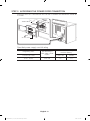
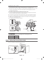
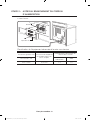
STEP 2. ACCESSING THE POWER CORD CONNECTION
Remove the rear access cover and loosen the screw with a screwdriver. The terminal block will then be
accessible.
Access cover
Terminal block
Specified power-supply-cord kit rating
Range rating, watts
Specified rating of
power-supply-cord kit,
amperes
Diameter (inches) of range
connection opening
120/240 volts 3-wire Power cord Conduit
8,750 - 16,500 40 or 50A 1
3
/8” 1
1
/8”
English - 6
Manual Installation_30 Oven_SECA_DG68-00109F-08_EN+CFR.indb 6 9/6/2018 6:52:51 PM

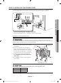
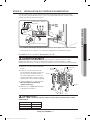
STEP 3. INSTALLING THE POWER CORD
For power cord installations, hook the strain relief over the power cord hole (1
3
/8”) located below the
rear of the drawer body. Insert the power cord through the strain relief and tighten the device.
Strain relief
Power cord
Conduit connection plate
• You must install the power cord with a strain relief.
• Attach the strain relief to the 1
3
/8” opening in conduit connection plate.
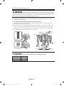
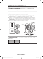
Installing a 3-wire power cord
WARNING
WARNING The neutral or ground wire of the power cord must be connected to the
neutral terminal located in the center of the terminal block. The power leads must be connected to the
lower left and the lower right terminals of the terminal block.
1. Remove the 3 lower terminal screws from the
terminal block.
2. Insert the 3 terminal screws through each
power cord terminal ring and into the lower
terminals of the terminal block. Be certain that
the center wire (white/neutral) is connected to
the center lower position of the terminal block.
3. Tighten screws securely into the terminal
block. DO NOT remove the ground strap
connection.
4. Go to step 5 on page 10 and proceed with
the installation.
Ground strap
Neutral
terminal
Black
White
Red
Black
White
Red
Live 1
Live 2
CAUTION
CAUTION You must check voltage after connecting power cord.
Live 1 - Neutral 120 V
Live 2 - Neutral 120 V
Live 1 - Live 2 208 V / 240 V
English - 7
02 CONNECTING THE POWER
Manual Installation_30 Oven_SECA_DG68-00109F-08_EN+CFR.indb 7 9/6/2018 6:52:52 PM

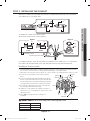
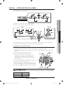
Installing a 4-wire power cord
WARNING
WARNING The neutral wire of the supply circuit must be connected to the neutral terminal
located in the lower center of the terminal block. The power leads must be connected to the lower left
and the lower right terminals of the terminal block. The 4th grounding lead must be connected to the
frame of the range with the ground plate and the ground screw.
1. Remove the 3 lower terminal screws from the terminal block. Remove the ground screw and
ground plate and retain them.
2. Cut and discard the ground strap. Do not discard any screws.
3. Insert the one ground screw into the power cord ground wire terminal ring, through the ground
plate, and into the frame of the range.
4. Insert the 3 terminal screws (removed earlier) through each power cord terminal ring and into the
lower terminals of the terminal block. Be certain that the center wire (white/neutral) is connected
to the center lower position of the terminal block. Tighten screws securely into the terminal block.
5. Go to step 5 on page 10 and proceed with the installation.
Ground strap
Ground plate
Ground
screw
Neutral
terminal
Ground
wire (Green)
White
Black
Red
Black
White
Red
Live 1
Live 2
CAUTION
CAUTION You must check voltage after connecting power cord.
Live 1 - Neutral 120 V
Live 2 - Neutral 120 V
Live 1 - Live 2 208 V / 240 V
English - 8
Manual Installation_30 Oven_SECA_DG68-00109F-08_EN+CFR.indb 8 9/6/2018 6:52:52 PM

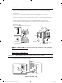
STEP 4. INSTALLING THE CONDUIT
Remove the conduit connection plate from the rear of the drawer body and rotate it as shown below.
The conduit hole (1
1
/8”) must be used.
1
1
/8” 1
3
/8”
1
1
/8”1
3
/8”
1. Prepare the conduit cord shown in Figure 1.
2. Install the conduit cord as shown in Figure 2.
Conduit connection plate
Strain relief
Ring
Body
Figure 2
1”
3
1
/2”
3
/8” 1”
3
1
/2”
3 wire 4 wire
Knockout surface
Figure 1
3
/8”
For conduit installations, insert the strain relief (not included) into the conduit hole (1
1
/8”). Then thread
the conduit cord through the body of the strain relief and fasten the ring. Reinstall the bracket.
Installing a 3-wire conduit
• Aluminum building wire may be used but it must be rated for the correct amperage and voltage to make
the connection. Connect wires according to Step 4 depending on the number of wires.
• Wire used, location and enclosure of splices, etc., must conform to good wiring practices and local codes.
1. Loosen the 3 lower terminal screws from the terminal
block.
2. Insert the center bare wire (white/neutral) tip through the
bottom center terminal block opening. On certain models,
the wire will need to be inserted through the ground strap
opening and then into the bottom center block opening.
3. Insert the two side bare wire tips into the lower left and
the lower right terminal block openings.
4. Tighten the screws until the wire is firmly secured (35 to
50 inch-lbs.). Do not over-tighten the screws since it could
damage the wires.
5. Go to step 5 on page 10 and proceed with the
installation.
White
Black
Red
Ground
strap
Neutral
terminal
Wire tips
Red
White
Black
Live 2
Live 1
CAUTION
CAUTION You must check voltage after connecting power cord.
Live 1 - Neutral 120 V
Live 2 - Neutral 120 V
Live 1 - Live 2 208 V / 240 V
English - 9
02 CONNECTING THE POWER
Manual Installation_30 Oven_SECA_DG68-00109F-08_EN+CFR.indb 9 9/6/2018 6:52:53 PM

Installing a 4-wire conduit
• Aluminum building wire may be used but it must be rated for the correct amperage and voltage to make
the connection. Connect wires according to this Step 4 depending on the number of wires.
• Wire used, location and enclosure of splices, etc., must conform to good wiring practices and local codes.
1. Loosen the 3 lower terminal screws from the terminal block. Remove the ground screw and
ground plate and retain them.
2. Cut and discard the ground strap. Do not discard any screws.
3. Insert the ground bare wire tip between the range frame and the ground plate (removed earlier)
and secure it in place with the ground screw (removed earlier).
4. Insert the bare wire (white/neutral) tip through the bottom center of the terminal block opening.
5. Insert the two side bare wire tips into the lower left and the lower right terminal block openings.
6. Tighten the screws until the wire is firmly secured (35 to 50 inch-lbs.). Do not over-tighten the
screws since it could damage the wires.
7. Go to step 5 and proceed with the installation.
Ground strap
Ground plate
White
Black
Red
Neutral
terminal
Ground
wire (Green)
Wire tips
White
Black
Red
Live 2
Live 1
CAUTION
CAUTION You must check voltage after connecting power cord.
Live 1 - Neutral 120 V
Live 2 - Neutral 120 V
Live 1 - Live 2 208 V / 240 V
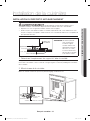
STEP 5. REPLACING THE ACCESS COVER
Replace the access cover on the range back. To replace the wire cover, insert double projections in the
pockets located below the opening and tighten the screw.
English - 10
Manual Installation_30 Oven_SECA_DG68-00109F-08_EN+CFR.indb 10 9/6/2018 6:52:54 PM

installing the range
INSTALLING THE ANTI-TIP DEVICE
WARNING
WARNING To reduce the risk of tipping, the appliance must be secured by properly
installing the Anti-Tip device packed with the appliance.
• Refer to the installation instructions supplied with the bracket.
• Unless properly installed, the range could be tipped by stepping or sitting on the door. Injury may
result from spilled hot liquids or from the range itself.
Anti-Tip
bracket
Screw must enter wood or
concrete
*approximately
21/32”(16.5mm)
*NOTE: To install Anti-Tip bracket,
release the leveling leg. A minimum
clearance of 21/32”(16.5mm) is required
between the range bottom and the
kitchen floor.
1. Locate the bracket using the template
The Anti-Tip bracket is packaged with a template. The instructions include information necessary to
complete the installation. Read and follow the instructions on the sheet (template) for range installation.
2. Level the range
Level the range by adjusting the leveling legs with a wrench.
Lower range
Raise range
Leveling leg
English - 11
03 INSTALLING THE RANGE
Manual Installation_30 Oven_SECA_DG68-00109F-08_EN+CFR.indb 11 9/6/2018 6:52:54 PM

3. Check your adjustments
Use a spirit level to check your adjustments. Place the level diagonally on the oven rack or surface
cooktop, and check each direction for level.
1. Check direction 1.
2. Check direction 2.
If the spirit level doesn’t show level on the oven rack
or surface cooktop, adjust the leveling legs with a
wrench.
CAUTION
CAUTION For your safety, do not
attempt to modify or straighten front legs. Front
leveling legs on the range are designed to be
slanted to prevent accidental tipping.
Ground
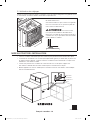
FINALIZING THE INSTALLATION
• Move range close enough to the opening to plug into the receptacle.
• Slide range into position insuring that the rear left(or rear right) leg slides under the Anti-Tip bracket.
The range will sit 0” away from the back wall when properly installed.
• Carefully tip the range forward to insure that the Anti-Tip bracket engages the back brace and
prevents tip-over.
• Turn on the electrical power. Check the range for proper operation as described in the user manual.
Anti-Tip bracket
Leveling leg
DG68-00109F-08
English - 12
Manual Installation_30 Oven_SECA_DG68-00109F-08_EN+CFR.indb 12 9/6/2018 6:52:55 PM

un monde de possibilités
Nous vous remercions d'avoir choisi ce produit Samsung.
Cuisinière électrique
Manuel d'installation
Manual Installation_30 Oven_SECA_DG68-00109F-08_EN+CFR.indb 1 9/6/2018 6:52:56 PM

avant de commencer
DISPOSITIF ANTI-BASCULEMENT
AVERTISSEMENT: Pour réduire le risque de basculement de l’appareil, ce dernier
doit être sécurisé à l’aide des dispositifs anti-basculement correctement installés,
fournis dans l’emballage.
a) Un enfant ou un adulte peut renverser la cuisinière et être tué.
b) Installez le dispositif anti-basculement sur la structure et/ou la cuisinière, côté
arrière droit (ou arrière gauche) de la partie inférieure de la cuisinière.
c) Engagez la cuisinière dans le dispositif anti-basculement avec le pied réglable côté
arrière droit (ou arrière gauche) de la partie inférieure de la cuisinière.
d) Réengagez le dispositif anti-basculement si la cuisinière s’est déplacée.
e) Voir les instructions d’installation pour plus de détails.
f) Le non-respect de ces consignes peut occasionner la mort ou de graves
blessures, pour les enfants comme pour les adultes.
A PROPOS DE CE MANUEL
LISEZ ENTIÈREMENT ET ATTENTIVEMENT CES INSTRUCTIONS.
Note importante destinée à l'installateur
• Lisez l'intégralité des consignes d'installation avant d'installer la cuisinière.
• Retirez tous les éléments d'emballage des compartiments du four avant de raccorder la cuisinière à
l'alimentation électrique.
• Respectez tous les codes et règlements en vigueur.
• Assurez-vous de laisser ces instructions à l'utilisateur.
Note importante destinée à l'utilisateur
Conservez précieusement ces instructions afin que la personne chargée du contrôle
électrique puisse s'y reporter.
• Comme pour tout appareil générant de la chaleur, certaines consignes de sécurité sont à respecter.
• Assurez-vous que votre appareil est correctement installé et mis à la terre par un installateur qualifié
ou un technicien spécialisé.
• Assurez-vous que les revêtements muraux situés à proximité de l'appareil peuvent résister à la
chaleur générée par celui-ci.
• Pour ne pas avoir à accéder à l'espace au-dessus des éléments de cuisson, évitez d'y aménager
des meubles de rangement.
• La cuisinière ne doit pas être placée sur un socle.
POUR VOTRE SÉCURITÉ
AVERTISSEMENT
AVERTISSEMENT Si vous ne respectez pas scrupuleusement les
informations contenues dans ce manuel, vous risquez de provoquer un incendie ou un choc électrique
et, par conséquent, des dégâts matériels, blessures ou accidents mortels.
AVERTISSEMENT
AVERTISSEMENT Avant de démarrer l'installation, coupez l'alimentation
au panneau de commande et verrouillez les dispositifs de débranchement de la mise en service;
cette précaution évitera toute mise sous tension accidentelle de l'appareil. Si vous ne parvenez pas
à verrouiller les moyens de débranchement de la mise en service, fixez fermement au panneau de
commande un dispositif d'alarme bien visible.
AVERTISSEMENT
AVERTISSEMENT Cet appareil doit être correctement mis à la terre.
AVERTISSEMENT
Français canadien - 2
Manual Installation_30 Oven_SECA_DG68-00109F-08_EN+CFR.indb 2 9/6/2018 6:52:56 PM

préparation avant l'installation de la cuisinière
RETRAIT DE L'EMBALLAGE
Retirez le matériel d'emballage. Tout matériel d'emballage non retiré risque d'endommager l'appareil.
PREPARATION DES OUTILS ET DES PIECES
Outils nécessaires
Perceuse Clé à molette Pince Tournevis à douille de
1
/4˝
Tournevis cruciforme Tournevis plat Crayon Niveau
Accessoires fournis
Modèle Support anti-basculement Vis (4ch)
Cordon 4fils ou 3fils
(homologué UL 40 ou 50AMP)
Accessoires non fournis
Protection contre la traction
(pour le branchement des
gaines uniquement)
Français canadien - 3
01
AVANT DE COMMENCER & PRÉPARATION AVANT L’INSTALLATION DE LA CUISINIÈRE
Manual Installation_30 Oven_SECA_DG68-00109F-08_EN+CFR.indb 3 9/6/2018 6:52:58 PM

VÉRIFICATION DU LIEU D'INSTALLATION
Dégagements et dimensions
Pour procéder à l'installation de la cuisinière, reportez-vous au schéma suivant.
Concernant les installations au CANADA, une cuisinière non encastrable ne peut pas être
installée à moins de 12mm de toute surface adjacente.
ATTENTION
ATTENTION Cette cuisinière a été conçue pour supporter une température maximale
de 194 ºF, température maximale autorisée pour toute structure en bois. Assurez-vous que le revêtement
mural, les plans de travail et les meubles voisins peuvent résister à la chaleur (jusqu'à 194 ºF) générée par
la cuisinière. Dans le cas contraire, des éléments peuvent se décolorer, se décoller ou fondre.
A
B
36" ~ 37"
46
1
/2
" ~ 47
1
/2
"
29
15
/16"
1
9
/16
"
24
7
/8"
7
1
/2"
24
1
/2"
26
1
/16"
49
3
/8"
28
7
/16"
29
7
/8"
6"
25"
3"
24"
3"
A: Ouverture du
meuble
30” pour les Etats-Unis,
30”~31” pour le
CANADA.
B: emplacement
autorisé pour la
prise électrique
Dimensions minimales
IMPORTANT Pour éliminer tout risque de brûlure ou d'incendie lors de l'accès
à l'espace situé au-dessus des éléments de cuisson chauds, évitez d'y aménager tout meuble de
rangement. Si, toutefois, un meuble de rangement doit être monté, réduisez ce risque en installant une
hotte d'aspiration assurant une protection horizontale d'au moins 5" au-delà du dessous du meuble.
* 30”
30”
** 15”
* dégagement minimal de 30” entre le
dessus de la table de cuisson et le
dessous d'un meuble en métal ou en bois
non protégé, ou de 24” minimum si le
dessous du meuble en métal ou en bois
est protégé par un carton pâte inifugeant
d'au moins
1
/4” recouvert par au moins
une feuille d'acier n°28 MSG, d'acier
inoxydable de 0.015”, d'aluminium de
0.024” ou de cuivre de 0.020”.
** 15” minimum entre le plan de travail et le
dessous du meuble adjacent.
Français canadien - 4
Manual Installation_30 Oven_SECA_DG68-00109F-08_EN+CFR.indb 4 9/6/2018 6:52:58 PM

Mise sous tension
ETAPE 1: RESPECT DES EXIGENCES EN MATIERE DE
RACCORDEMENTS ELECTRIQUES
ATTENTION
ATTENTION
Pour votre sécurité, n'utilisez pas de rallonge pour brancher
l'appareil. Retirez le fusible de l'installation électrique ou ouvrez le disjoncteur avant de
démarrer l'installation.
Cet appareil doit être alimenté par la fréquence et la tension adaptées. Il doit
également être branché sur un circuit individuel correctement mis à la terre et
protégé par un disjoncteur ou un fusible dont l'ampérage est conforme à celui
spécifié sur la plaque signalétique de l'appareil. La plaque signalétique est
située au-dessus du tiroir sur la structure du four. (Fig. 1 ou Fig. 2)
Nous vous recommandons de confier le câblage et le branchement électriques
de votre cuisinière à un électricien qualifié. Une fois l'installation eectuée,
demandez à l'électricien de vous montrer l'emplacement de débranchement
principal de votre cuisinière.
Vérifiez auprès de votre service public les codes électriques s'appliquant à votre
zone. Le non-respect des codes obligatoires pour le branchement de votre
four peut s'avérer dangereux. S'il n'existe pas de codes locaux, votre
cuisinière doit être branchée conformément aux exigences du Code
national électrique, ANSI/NFPA N°70 (dernière édition). Vous pouvez
en obtenir une copie en adressant un courrier à:
National Fire Protection Association
Batterymarch Park
Quincy, MA 02269
Entré en vigueur le 1er janvier 1996, le Code électrique national exige que toute construction neuve
(non existante) doit être équipée d'un branchement à 4conducteurs pour les cuisinières électriques.
Lorsque vous installez une cuisinière électrique dans une construction neuve, suivez les
étapes 2 et 3 relatives aux connexions à 4fils.
Vous devez utiliser un système électrique à 3 ou 4fils, monophasé CA de 208Y/120 V ou de 240/120 V (60Hz).
Si votre installation électrique n'est pas conforme aux spécifications ci-dessus, contactez un électricien
agréé afin d'installer une prise homologuée.
Utilisez uniquement un cordon d'alimentation à 3 ou 4fils figurant dans la liste UL. Ces cordons
nécessitent des bornes rondes sur le fil et un dispositif de protection contre la traction.
Un cordon d'alimentation nominale de 40A et de 125/250V minimum est indispensable. Il n'est pas
recommandé d'utiliser un cordon d'alimentation de 50A, mais si toutefois vous en utilisé un, celui-ci
doit être repéré pour être utilisé avec des ouvertures de connexion de diamètre nominal 1
3
⁄8”. Veillez
à bien centrer le câble et le dispositif de protection contre la traction dans le trou d'éjection afin
d'empêcher que le bord n'endommage le câble.
• Etant donné que les prises de la cuisinière sont inaccessibles une fois la cuisinière installée, il est
nécessaire d'utiliser une gaine ou un cordon flexible.
REMARQUE Si vous utilisez une gaine, suivez l'étape4, page9.
TOUTES LES CONSTRUCTIONS DONT LES CIRCUITS DERIVES SONT NEUFS,
LES MAISONS MOBILES, LES VEHICULES ET LES INSTALLATIONS DE LOISIRS
DONT LES CODES LOCAUX NE PERMETTENT PAS UNE MISE A LA TERRE
PAR UNE BORNE NEUTRE, NECESSITENT L'UTILISATION D'UN CORDON
D'ALIMENTATION A 4FILS FIGURANT DANS LA LISTE UL.
(Fig. 1).
(Fig. 2).
Français canadien - 5
02 MISE SOUS TENSION
Manual Installation_30 Oven_SECA_DG68-00109F-08_EN+CFR.indb 5 9/6/2018 6:52:59 PM

ETAPE 2: ACCES AU BRANCHEMENT DU CORDON
D'ALIMENTATION
Retirez le panneau d'accès situé à l'arrière et desserrez la vis à l'aide d'un tournevis. Vous pourrez alors
accéder au bornier.
Capot d'accès
Bornier
Classification de l'équipement nécessaire à la mise sous tension
Classification générale, watts
Classification de l'équipement
nécessaire à la mise sous
tension, ampères
Diamètre (pouces) de l'ouverture de
connexion de la cuisinière
120 / 240volts, 3fils
Cordon
d'alimentation
Gaine
8750 - 16500 40 ou 50A 1
3
/8” 1
1
/8”
Français canadien - 6
Manual Installation_30 Oven_SECA_DG68-00109F-08_EN+CFR.indb 6 9/6/2018 6:52:59 PM

ETAPE 3: INSTALLATION DU CORDON D'ALIMENTATION
Pour les installations de cordons d'alimentation, branchez le dispositif de protection de câble
sur l'orifice du cordon d'alimentation (1
3
/8”) situé sous la partie arrière du tiroir. Insérez le cordon
d'alimentation dans le dispositif et serrez-le.
Protection contre la traction
Cordon
d'alimentation
Plaque de raccordement
des gaines
• Le cordon d'alimentation doit être installé au moyen d'une protection contre la traction.
• Fixez la protection à l'ouverture 1
3
/8” située dans la plaque de raccordement des gaines.
Installation d'un cordon d'alimentation à 3fils
AVERTISSEMENT
AVERTISSEMENT La prise de terre ou la prise neutre du cordon
d'alimentation doit être connectée à la borne neutre située au centre du bornier. Les câbles
d'alimentation doivent être connectés aux bornes inférieures gauches et inférieures droites du bornier.
1. Retirez les 3vis de la borne inférieure du
bornier.
2. Insérez les 3vis de la borne dans les
bornes inférieures du bornier en passant
par chacun des anneaux de la borne
du cordon d'alimentation. Assurez-vous
que le fil central (blanc/neutre) est relié à
l'emplacement central inférieur du bornier.
3. Serrez fermement les vis dans le bornier.
NE retirez PAS la connexion du
conducteur de terre.
4. Reportez-vous à l'étape5 de la page10
et procédez à l'installation.
Conducteur
de terre
Borne
neutre
Noir
Blanc
Rouge
Noir
Blanc
Rouge
Phase 1
Phase 2
ATTENTION
ATTENTION
Vous devez vérifier la tension après avoir branché le cordon
d’alimentation.
Phase1 - Neutre 120 V
Phase2 - Neutre 120 V
Phase1 - Phase2 208 V / 240 V
Français canadien - 7
02 MISE SOUS TENSION
Manual Installation_30 Oven_SECA_DG68-00109F-08_EN+CFR.indb 7 9/6/2018 6:53:00 PM

Installation d'un cordon d'alimentation à 4fils
AVERTISSEMENT
AVERTISSEMENT La prise neutre du circuit d'alimentation doit être
connectée à la borne neutre située au centre inférieur du bornier. Les câbles d'alimentation doivent être
connectés aux bornes inférieures gauches et inférieures droites du bornier. Le 4ème câble de mise à la
terre doit être connecté au bâti de la cuisinière au moyen de la plaque et de la vis de masse.
1. Retirez les 3vis de la borne inférieure du bornier. Retirez la vis et la plaque de terre et conservez-
les.
2. Coupez et éliminez le conducteur de terre. Ne jetez aucune vis.
3. Insérez la première vis de terre dans l'anneau de la borne du fil de mise à la terre du cordon
d'alimentation, en passant par la plaque de masse puis dans le bâti de la cuisinière.
4. Insérez les 3vis de la borne (retirées précédemment) dans les bornes inférieures du bornier en
passant par chacun des anneaux de la borne du cordon d'alimentation. Assurez-vous que le fil
central (blanc/neutre) est relié à l'emplacement central inférieur du bornier. Serrez fermement les
vis dans le bornier.
5. Reportez-vous à l'étape5 de la page10 et procédez à l'installation.
Conducteur de terre
Plaque de terre
Vis de
terre
Borne
neutre
Fil de
terre (Vert)
Blanc
Noir
Rouge
Noir
Blanc
Rouge
Phase 1
Phase 2
ATTENTION
ATTENTION
Vous devez vérifier la tension après avoir branché le cordon
d’alimentation.
Phase1 - Neutre 120 V
Phase2 - Neutre 120 V
Phase1 - Phase2 208 V / 240 V
Français canadien - 8
Manual Installation_30 Oven_SECA_DG68-00109F-08_EN+CFR.indb 8 9/6/2018 6:53:00 PM
La page charge ...
La page charge ...
La page charge ...
La page charge ...
-
 1
1
-
 2
2
-
 3
3
-
 4
4
-
 5
5
-
 6
6
-
 7
7
-
 8
8
-
 9
9
-
 10
10
-
 11
11
-
 12
12
-
 13
13
-
 14
14
-
 15
15
-
 16
16
-
 17
17
-
 18
18
-
 19
19
-
 20
20
-
 21
21
-
 22
22
-
 23
23
-
 24
24


Samsung NE59M7630SG/AC Manuel utilisateur
- Taper
- Manuel utilisateur
dans d''autres langues
- English: Samsung NE59M7630SG/AC User manual
Documents connexes
-
Samsung NE595R0ABSR/AC Le manuel du propriétaire
-
-
-
Samsung NE63A6711SS/AC Guide d'installation
-
Samsung NE63T8951SS/AC Guide d'installation
-
-
-
Samsung NE58H9970WS/AC Guide d'installation
-
Samsung NY63T8751SG Guide d'installation