Samsung NE58R9311SS/AC Manuel utilisateur
- Taper
- Manuel utilisateur

Electric Range
installation manual
imagine the possibilities
Thank you for purchasing this Samsung product.
Install_NE58H9970WS_AA_AC_DG68-00594B-00_EN+CFR.indb 1 6/7/2019 12:45:41 PM

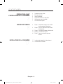
contents
PREPARING TO INSTALL THE
RANGE
3
3 About this section
3 For your safety
4 Remove packaging
4 Prepare tools & Parts
5 Checking the installation site
7 To avoid breakage
CONNECTING THE POWER
8
8 Step 1. Meeting electrical
connection requirements
9 Step 2. Accessing the power cord
connection
10 Step 3. Installing the power cord
13 Step 4. Installing the conduit
16 Step 5. Replacing the access cover
INSTALLING THE RANGE
17
17 Installing the anti-tip device
19 Finalizing the installation
English - 2
Install_NE58H9970WS_AA_AC_DG68-00594B-00_EN+CFR.indb 2 6/7/2019 12:45:41 PM

preparing to install the range
ABOUT THIS SECTION
READ THESE INSTRUCTIONS COMPLETELY AND CAREFULLY.
Important note to the installer
• Read all instructions contained in these installation instructions before installing
the range.
• Remove all packing materials from the oven compartments before connecting the
electrical supply to the range.
• Observe all governing codes and ordinances.
• Be sure to leave these instructions with the consumer.
Important note to the consumer
Keep these instructions for the local electrical inspector’s use.
• As when using any appliance generating heat, there are certain safety precautions
you should follow.
• Be sure your range is installed and grounded properly by a qualified installer or
service technician.
• Make sure the wall coverings around the range can withstand the heat generated
by the range.
• To eliminate the need to reach over the surface elements, avoid having cabinet
storage space above the cooktop.
• The range should not be placed on a base.
FOR YOUR SAFETY
WARNING
WARNING If the information in this manual is not followed exactly, a
fire or electrical shock may result causing property damage, personal injury, or death.
WARNING
WARNING Before beginning the installation, switch the power o at
the service panel and lock the service disconnecting switch to prevent power from being
switched on accidentally. When the service disconnecting switch cannot be locked,
securely fasten a prominent warning device, such as a tag, to the service panel.
WARNING
WARNING This appliance must be properly grounded.
English - 3
01 PREPARING TO INSTALL THE RANGE
Install_NE58H9970WS_AA_AC_DG68-00594B-00_EN+CFR.indb 3 6/7/2019 12:45:41 PM

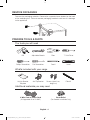
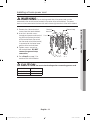
REMOVE PACKAGING
Remove the packaging materials. Remove the supporter frame located on the back
of the cooktop glass. Failure to remove packaging materials could result in damage
to the appliance.
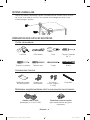
PREPARE TOOLS & PARTS
The tools you will need
Drill Adjustable Wrench Pliers
1
/4" Nut Driver
Phillips Screwdriver Flat Screwdriver Pencil Level
What’s included with your range
Anti-tip Bracket
Template
Anti-Tip Bracket Screws (short:2 ea,
long:2 ea)
Filler Kit
Additional materials you may need
4-Wire Cord or 3-Wire Cord
(UL Approved 40 or 50 AMP)
Strain Relief
(For Conduit Installation Only)
English - 4
Install_NE58H9970WS_AA_AC_DG68-00594B-00_EN+CFR.indb 4 6/7/2019 12:45:41 PM

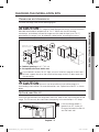
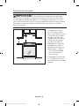
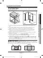
CHECKING THE INSTALLATION SITE
Clearances and dimensions
To install the range, refer to the following figure.
CAUTION
CAUTION This range has been designed to comply with the maximum
allowable wood cabinet temperatures of 194 °F. Make sure the wall covering,
countertops, and cabinets around the range can withstand the heat (up to 194 °F)
generated by the range. If not, discoloration, delamination, or melting may occur.
SLIDE-IN CUTOUT FREESTANDING CUTOUT
A
B
A
36"~36-3/4"
31"
4-1/2"
23-3/16"
6-5/16"
24-11/16"
48"
28-5/8"
26-5/16"
29-15/16"
26-5/16"
Hatched Faces should
be flat and leveled.
35-7/8"
23-3/16"
1/2" min.
25"
6"
3"
24"
3"
1" min.
A
B
6"
25"
3"
24"
3"
A : Cabinet opening min 30" (76.2 cm)
B : Acceptable electrical outlet area
If your cabinets are over 36-3/4" high, you must install this range on a hard, heat
resistant support that raises the surface of the range so that it is about even with
the countertop.
CAUTION
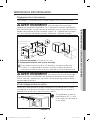
CAUTION You must use the rear filler kit to install the range in a
freestanding cutout cabinet. For more information, see “Optional rear filler kit” as shown
below.
Optional rear filler kit
Used to fill gap between the range back and wall. Adds a filler strip to the rear of the
range. This kit can only be used when the opening in the countertop is 25” deep.
If the countertop depth is
greater than 25", there will
be a gap between the filler kit
and the back wall.
English - 5
01 PREPARING TO INSTALL THE RANGE
Install_NE58H9970WS_AA_AC_DG68-00594B-00_EN+CFR.indb 5 6/7/2019 12:45:41 PM

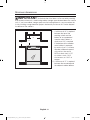
Minimum dimensions
IMPORTANT To eliminate the risk of burns or fire caused by reaching
over heated surface units, avoid having cabinet storage space located above the surface
units. If you have cabinet storage space over the heating elements, you can reduce the
risk by installing a range hood that projects horizontally a minimum of 5 inches beyond
the bottom of the cabinets.
* 30"
30"
** 15"
* A minimum of 30" is required
between the top of the
cooking surface and the
bottom of an unprotected
wood or metal cabinet; a
minimum of 24" is required
if the bottom of the wood or
metal cabinet is protected
by not less than
1
/4" of flame
retardant millboard covered
with not less than no.28
MSG of sheet steel, 0.015"
of stainless steel, 0.024"
of aluminum, or 0.020" of
copper.
** A minimum of 15" is required
between the countertop and
the adjacent cabinet bottom.
English - 6
Install_NE58H9970WS_AA_AC_DG68-00594B-00_EN+CFR.indb 6 6/7/2019 12:45:41 PM

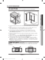
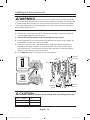
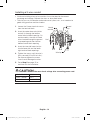
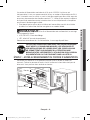
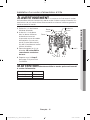
TO AVOID BREAKAGE
CAUTION
CAUTION Do NOT lift or handle the unit by the cooktop glass.
Fig. 1
C1
C3
C2
C4
1. The counter top around the cut-out should be flat and leveled (see hatched area on
Fig. 1).
2. Before installing the unit, measure the heights of the two cabinet sides (C1~C4),
front and back (See Fig. 1) from the floor to the top of the counter.
3. Level the range using the four leveling legs so that the height from the floor
to the underside of the cooktop glass frame is greater than the tallest cabinet
measurement by at least 1/16".
4. Remove the Support Frames on the back left and back right of the glass cooktop
(Refer to page 4).
5. Slide the unit into the cabinet (DO NOT PUSH THE UNIT HARD). Make sure the
center of the unit aligns with the center of the cabinet cut-out.
6. The cooktop glass frame under the cooktop glass MUST sit above the cabinet
countertop so the unit is supported by its leveling legs. The cooktop glass should
NOT directly touch the countertop If the cooktop glass is touching the countertop,
it could break, voiding the warranty.
IMPORTANT MAKE SURE the unit is supported by the leveling legs
and NOT by the cooktop itself. The cooktop glass must sit above the surface of the
countertops.
English - 7
01 PREPARING TO INSTALL THE RANGE
Install_NE58H9970WS_AA_AC_DG68-00594B-00_EN+CFR.indb 7 6/7/2019 12:45:42 PM

connecting the power
STEP 1. MEETING ELECTRICAL CONNECTION
REQUIREMENTS
CAUTION
CAUTION For personal safety, do not use an extension cord
with this appliance. Remove the house fuse or open the circuit breaker before
beginning installation.
This appliance must be supplied with the proper voltage
and frequency, and be connected to an individual, properly
grounded branch circuit, protected by a circuit breaker or fuse
having amperage as specified on the rating plate. The rating
plate is located above the drawer on the oven frame. (Fig. 1 or
Fig. 2)
We recommend you have the electrical wiring and hookup
of your range connected by a qualified electrician. After
installation, have the electrician show you where your main
range disconnect is located.
Check with your local utilities for electrical codes which apply
in your area. Failure to wire your oven according
to governing codes could result in a hazardous
condition. If there are no local codes, your range must
be wired and fused to meet the requirements of the
National Electrical Code, ANSI/NFPA No.
70–Latest
Edition. You can get a copy by writing:
National Fire Protection Association
Batterymarch Park
Quincy, MA 02269
Eective January 1, 1996, the National Electrical Code requires that new
construction (not existing) utilize a 4-conductor connection to an electric
range.
When installing an electric range in new construction, follow Steps 2 and 3
for a 4-wire connection.
You must use a 3-wire or 4-wire, single-phase A.C. 208Y/120 Volt or 240/120 Volt,
60 hertz electrical system.
If the electrical service provided does not meet the above specifications, have a
licensed electrician install an approved outlet.
Use only a 3-conductor or a 4-conductor UL-listed range cord. These cords may be
provided with ring terminals on the wire and a strain relief device.
(Fig. 1)
(Fig. 2)
English - 8
Install_NE58H9970WS_AA_AC_DG68-00594B-00_EN+CFR.indb 8 6/7/2019 12:45:42 PM

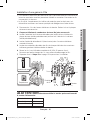
A range cord rated at 40 amps with 125/250 minimum volt range is required. A 50
amp range cord is not recommended but if used, it should be marked for use with
nominal 1
3
⁄8" diameter connection openings. Care should be taken to center the
cable and strain relief within the knockout hole to keep the edge from damaging the
cable.
• Because range terminals are not accessible after the range is in position, a flexible
service conduit or cord must be used.
NOTE If the power connection is plugged in improperly, the following
message appears on the display.
• LCD, PMOLED : Wire installation fail
• LED : bAd LinE
Reconnect the power connection properly, and the message disappears.
ALL NEW BRANCH-CIRCUIT CONSTRUCTIONS, MOBILE HOMES,
RECREATIONAL VEHICLES, AND INSTALLATIONS WHERE LOCAL
CODES DO NOT ALLOW GROUNDING THROUGH NEUTRAL,
REQUIRE A 4-CONDUCTOR UL-LISTED RANGE CORD.
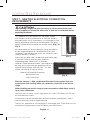
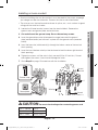
STEP 2. ACCESSING THE POWER CORD CONNECTION
Loosen and then remove the rear access cover screw with a screwdriver. Remove
the rear access cover by pull right and then out. The terminal block will then be
accessible.
Access cover
Terminal block
English - 9
02 CONNECTING THE POWER
Install_NE58H9970WS_AA_AC_DG68-00594B-00_EN+CFR.indb 9 6/7/2019 12:45:42 PM

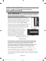
Specified rating of power-supply-cord kit and circuit
protection
Range rating, watts
Specified rating
of power-supply-
cord kit and circuit
protection, Amps
Diameter (inches) of range
connection opening
120/240 volts
3-wire
120/208 volts
3-wire
Power cord Conduit
8750 - 16500 7801 - 12500 40 or 50 A 1
3
/8" 1
1
/8"
This appliance must be supplied with the proper voltage at the proper frequency
and must be connected to a dedicated, properly grounded branch circuit protected
by a 40 amp or larger circuit breaker.
NOTE For power cord installations, go to page 10. For conduit installations,
go to page 13.
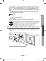
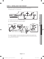
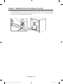
STEP 3. INSTALLING THE POWER CORD
For power cord installations, hook the strain relief over the power cord hole (1
3
/8")
located below the rear of the drawer body. Insert the power cord through the strain
relief and tighten the device.
Strain relief
Power cord
Conduit connection plate
• You must install the power cord with a strain relief.
• Attach the strain relief to the 1
3
/8" opening in the conduit connection plate.
English - 10
Install_NE58H9970WS_AA_AC_DG68-00594B-00_EN+CFR.indb 10 6/7/2019 12:45:43 PM

Installing a 3-wire power cord
WARNING
WARNING
The neutral or ground wire of the power cord must be
connected to the neutral terminal located in the center of the terminal block. The power
leads must be connected to the lower left and the lower right terminals of the terminal block.
1. Remove the 3 lower terminal
screws from the terminal block.
2.
Insert the 3 terminal screws
through each power cord terminal
ring and into the lower terminals
of the terminal block. Be certain
that the center wire (white/neutral)
is connected to the center lower
position of the terminal block.
3. Tighten screws securely to
the terminal block. DO NOT
remove the ground strap
connection.
4. Go to Step 5 on page 15 to
continue with the installation.
Ground strap
Neutral
terminal
Black
White
Red
Black
White
Red
Live 1
Live 2
CAUTION
CAUTION You must check voltage after connecting power cord.
Live 1 - Neutral 120 V
Live 2 - Neutral 120 V
Live 1 - Live 2 208 V / 240 V
English - 11
02 CONNECTING THE POWER
Install_NE58H9970WS_AA_AC_DG68-00594B-00_EN+CFR.indb 11 6/7/2019 12:45:43 PM

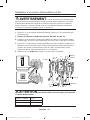
Installing a 4-wire power cord
WARNING
WARNING The neutral wire of the supply circuit must be connected
to the neutral terminal located in the lower center of the terminal block. The power leads
must be connected to the lower left and the lower right terminals of the terminal block.
The 4th grounding lead must be connected to the frame of the range with the ground
plate and the ground screw.
1. Remove the 3 lower terminal screws from the terminal block. Remove the ground
screw and ground plate and retain them.
2. Cut and discard the ground strap. Do not discard any screws.
3. Insert the ground screw into the power cord ground wire terminal ring, through the
ground plate, and into the frame of the range.
4. Insert the 3 terminal screws (removed earlier) through each power cord terminal
ring and into the lower terminals of the terminal block. Be certain that the center
wire (white/neutral) is connected to the center lower position of the terminal block.
Tighten screws securely to the terminal black.
5. Go to Step 5 on page 15 to continue with the installation.
Ground strap
Ground plate
Ground
screw
Neutral
terminal
Ground
wire (Green)
White
Black
Red
Black
White
Red
Live 2
Live 1
CAUTION
CAUTION You must check voltage after connecting power cord.
Live 1 - Neutral 120 V
Live 2 - Neutral 120 V
Live 1 - Live 2 208 V / 240 V
English - 12
Install_NE58H9970WS_AA_AC_DG68-00594B-00_EN+CFR.indb 12 6/7/2019 12:45:43 PM

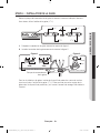
STEP 4. INSTALLING THE CONDUIT
Remove the conduit connection plate and rotate it as shown below.
The conduit hole (1
1
/8
") must be used.
1
1
/8" 1
3
/8"
1
1
/8"1
3
/8"
1. Prepare the conduit cord as shown in Figure 1.
2. Install the conduit cord as shown in Figure 2.
Conduit connection plate
Strain relief
Ring
Body
Figure 2
1"
3
1
/2"
3
/8" 1"
3
1
/2"
3 wire 4 wire
Knockout surface
Figure 1
3
/8"
For conduit installations, insert the strain relief (not included) into the conduit hole
(1
1
/8"). Then thread the conduit cord through the body of the strain relief and fasten
the ring. Reinstall the bracket.
English - 13
02 CONNECTING THE POWER
Install_NE58H9970WS_AA_AC_DG68-00594B-00_EN+CFR.indb 13 6/7/2019 12:45:43 PM

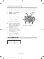
Installing a 3-wire conduit
• Aluminum building wire may be used but it must be rated for the correct
amperage and voltage. Connect the wires as described below.
• The wire you use, the location and enclosure of splices, etc., must conform to
good wiring practices and local codes.
1. Loosen the 3 lower terminal screws
from the terminal block.
2. Insert the center bare wire (white/
neutral) tip through the bottom
center terminal block opening. On
certain models, the wire will need
to be inserted through the ground
strap opening and then into the
bottom center block opening.
3. Insert the two side bare wire tips
into the lower left and the lower
right terminal block openings.
4. Tighten the screws until the wire is
firmly secured (35 to 50 inch-lbs.).
Do not over-tighten the screws
since it could damage the wires.
5. Go to Step 5 on page 15 to
continue with the installation.
White
Black
Red
Ground
strap
Neutral
terminal
Wire tips
Red
White
Black
Live 2
Live 1
CAUTION
CAUTION You must check voltage after connecting power cord.
Live 1 - Neutral 120 V
Live 2 - Neutral 120 V
Live 1 - Live 2 208 V / 240 V
English - 14
Install_NE58H9970WS_AA_AC_DG68-00594B-00_EN+CFR.indb 14 6/7/2019 12:45:43 PM

Installing a 4-wire conduit
• Aluminum building wire may be used but it must be rated for the correct amperage
and voltage to make the connection. Connect the wires as described below.
• The wire you use, the location and enclosure of splices, etc., must conform to good
wiring practices and local codes.
1. Loosen the 3 lower terminal screws from the terminal block. Remove the
ground screw and ground plate and retain them.
2. Cut and discard the ground strap. Do not discard any screws.
3. Insert the ground bare wire tip between the range frame and the ground
plate (removed earlier) and secure it in place with the ground screw (removed
earlier).
4.
Insert the bare wire (white/neutral) tip through the bottom center of the terminal
block opening.
5. Insert the two side bare wire tips into the lower left and the lower right terminal
block openings.
6. Tighten the screws until the wire is firmly secured (35 to 50 inch-lbs.). Do not
over-tighten the screws since it could damage the wires.
7. Go to Step 5 on page 15 to continue with the installation.
Ground strap
Ground plate
White
Black
Red
Neutral
terminal
Ground
wire (Green)
Wire tips
White
Black
Red
Live 2
Live 1
CAUTION
CAUTION You must check voltage after connecting power cord.
Live 1 - Neutral 120 V
Live 2 - Neutral 120 V
Live 1 - Live 2 208 V / 240 V
English - 15
02 CONNECTING THE POWER
Install_NE58H9970WS_AA_AC_DG68-00594B-00_EN+CFR.indb 15 6/7/2019 12:45:43 PM

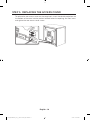
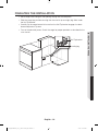
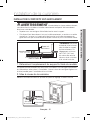
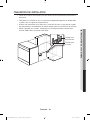
STEP 5. REPLACING THE ACCESS COVER
To replace the rear access cover on the range back. Insert the double projections on
the bottom of the cover into the pockets located below the opening, and then insert
and tighten the rear access cover screw.
English - 16
Install_NE58H9970WS_AA_AC_DG68-00594B-00_EN+CFR.indb 16 6/7/2019 12:45:44 PM

installing the range
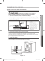
INSTALLING THE ANTI-TIP DEVICE
WARNING
WARNING To reduce the risk of tipping, you must secure the
appliance by properly installing the Anti-Tip device packed with the appliance.
• Refer to the installation instructions supplied with the bracket.
• If the anti-tip device is not installed properly, an adult or child stepping on or sitting
on the range door could tip the range and suer serious injuries caused by spilled hot
liquids or by the range itself.
Anti-Tip
bracket
Screw must enter
wood or concrete
*approximately
21/32" (16.5 mm)
*NOTE: To install
the Anti-Tip bracket,
release the leveling leg.
A minimum clearance
of 21/32" (16.5 mm) is
required between the
range bottom and the
kitchen floor.
1. Install the bracket using the template
The Anti-Tip bracket is packaged with a template. The instructions include
information necessary to complete the installation. Read and follow the instructions
on the sheet (template) for range installation.
2. Level the range
Level the range by adjusting the leveling legs with a wrench.
Lower range
Raise range
Leveling leg
English - 17
03 INSTALLING THE RANGE
Install_NE58H9970WS_AA_AC_DG68-00594B-00_EN+CFR.indb 17 6/7/2019 12:45:44 PM

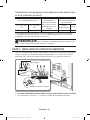
3. Check your adjustments
Use a spirit level to check your adjustments. Place the level diagonally on the oven
rack or surface cooktop, and confirm the range is level in the two directions shown
below.
1. Check direction 1.
2. Check direction 2.
If the spirit level indicates that
the range is not level, adjust the
leveling legs with a wrench.
English - 18
Install_NE58H9970WS_AA_AC_DG68-00594B-00_EN+CFR.indb 18 6/7/2019 12:45:44 PM

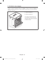
FINALIZING THE INSTALLATION
• Move range close enough to the opening to plug into the receptacle.
• Slide the range into position ensuring that the rear left (or rear right) leg slides under
the Anti-Tip bracket.
• Carefully tip the range forward to insure that the Anti-Tip bracket engages the back
brace and prevents tip-over.
• Turn on the electrical power. Check the range for proper operation as described in the
user manual.
Anti-Tip bracket
Leveling leg
English - 19
03 INSTALLING THE RANGE
Install_NE58H9970WS_AA_AC_DG68-00594B-00_EN+CFR.indb 19 6/7/2019 12:45:44 PM

For a Spanish version of this
manual, visit our Website at
www.samsung.com.
QUESTIONS OR COMMENTS?
COUNTRY CALL OR VISIT US ONLINE AT
U.S.A
Consumer Electronics
1-800-SAMSUNG (726-7864) www.samsung.com/us/support
CANADA 1-800-SAMSUNG (726-7864)
www.samsung.com/ca/support (English)
www.samsung.com/ca_fr/support (French)
DG68-00594B-00
Scan the QR code* or visit
www.samsung.com/spsn
to view our helpful
How-to Videos and Live Shows
* Requires reader to be installed on
your smartphone
Install_NE58H9970WS_AA_AC_DG68-00594B-00_EN+CFR.indb 20 6/7/2019 12:45:44 PM
La page est en cours de chargement...
La page est en cours de chargement...
La page est en cours de chargement...
La page est en cours de chargement...
La page est en cours de chargement...
La page est en cours de chargement...
La page est en cours de chargement...
La page est en cours de chargement...
La page est en cours de chargement...
La page est en cours de chargement...
La page est en cours de chargement...
La page est en cours de chargement...
La page est en cours de chargement...
La page est en cours de chargement...
La page est en cours de chargement...
La page est en cours de chargement...
La page est en cours de chargement...
La page est en cours de chargement...
La page est en cours de chargement...
La page est en cours de chargement...
-
 1
1
-
 2
2
-
 3
3
-
 4
4
-
 5
5
-
 6
6
-
 7
7
-
 8
8
-
 9
9
-
 10
10
-
 11
11
-
 12
12
-
 13
13
-
 14
14
-
 15
15
-
 16
16
-
 17
17
-
 18
18
-
 19
19
-
 20
20
-
 21
21
-
 22
22
-
 23
23
-
 24
24
-
 25
25
-
 26
26
-
 27
27
-
 28
28
-
 29
29
-
 30
30
-
 31
31
-
 32
32
-
 33
33
-
 34
34
-
 35
35
-
 36
36
-
 37
37
-
 38
38
-
 39
39
-
 40
40


Samsung NE58R9311SS/AC Manuel utilisateur
- Taper
- Manuel utilisateur
dans d''autres langues
- English: Samsung NE58R9311SS/AC User manual
Documents connexes
-
Samsung NE63A6711SS/AC Guide d'installation
-
-
Samsung NY63T8751SG Guide d'installation
-
Samsung NE63T8951SS/AC Guide d'installation
-
Samsung NE58R9560WG Guide d'installation
-
-
-
-
Samsung NZ36M9880UB Guide d'installation
-