
Installation and Care Guide
Vanity
Français, page ″Français-1″
Español, página ″Español-1″
1216526-2-F

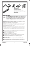
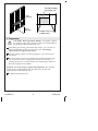
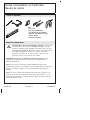
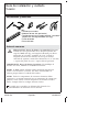
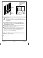
Tools and Materials
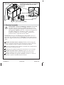
Before You Begin
CAUTION: Risk of property damage. Select 500 lb (227 kg)
load bearing 5/16″ lag bolts with a length to clear obstacles
in the wall and 5/16″ washers. Calculate proper lag bolt
length by adding the following: 1-1/2″ (38 mm) backing
material + wallboard thickness + back rail thickness.
IMPORTANT! Risk of product damage. Do not modify the vanity.
Doing so will compromise structural stability.
NOTICE: Siliconized acrylic caulk must be used to secure a sink or
countertop to the vanity. Do not use 100% silicone sealant which
will damage the finish of the vanity.
NOTICE: Any electrical accessory components must be connected
to a circuit protected by a Ground-Fault Circuit-Interrupter (GFCI)
or Residual Current Device (RCD). Follow all local electrical codes.
Your product may appear different than the one illustrated. The
installation procedures remain the same.
Observe all local building codes.
Two people should install this product.
Secure the vanity to stud framing. When possible, provide 2x6
bracing behind the finished wall for additional support.
This vanity is designed to allow most base moldings to pass
behind the vanity.
To ease installation, remove drawers from the vanity before
beginning. Refer to the section in this guide for proper removal.
Plus:
• Wood Screws
• 2x6s, 2x4s (Optional)
• 5/16" Lag Bolts and Washers
[Min 500 lb (227 kg) Load Bearing]
• Socket Wrenches
• Side Cutters
1216526-2-F 2 Kohler Co.

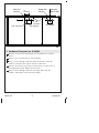
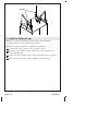
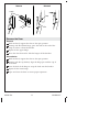
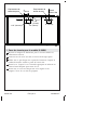
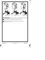
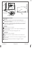
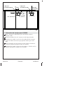
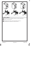
1. Hardware Placement for K-99688
Measure and mark the dimensions for the hardware as shown
above.
Drill a 3/16″ (21 mm) hole at each marking.
Insert a screw through each hole from the inside. Count the
number of notches that appear from the other side.
Remove the screw. Using a pair of side cutters, cut the screw at
the appropriate notch. Repeat for all screws.
Insert a screw through each hole and align them with the
handles. Thread the screws into the handles.
Drawer Pull
Location
Door Pull
Location
1-1/2" (38 mm)
3"
(76 mm)
3" (76 mm)
2-1/8"
(54 mm)
3" (76 mm)
Centered
Side to Side
Kohler Co. 3 1216526-2-F

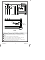
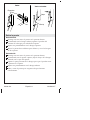
2. Hardware Placement for K-99686 and K-99689
Measure and mark the dimensions for the hardware as shown
above.
Drill a 3/16″ (21 mm) hole at each marking.
Insert a screw through each hole from the inside. Count the
number of notches that appear from the other side.
Remove the screw. Using a pair of side cutters, cut the screw at
the appropriate notch. Repeat for all screws.
1"
(25 mm)
Centered
Side to Side
4-5/8"
(117 mm)
K-99686 and K-99689
3" (76 mm)
4-5/8"
(117 mm)
K-99689
4-5/8"
(117 mm)
3" (76 mm)
4-1/4"
(108 mm)
1216526-2-F 4 Kohler Co.

Hardware Placement for K-99686 and K-99689 (cont.)
Insert a screw through each hole and align them with the
handles. Thread the screws into the handles.
Kohler Co. 5 1216526-2-F

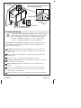
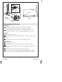
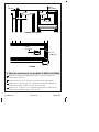
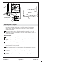
3. Preparation
CAUTION: Risk of property damage. To properly support
the weight of the vanity and sink, secure to stud framing or
2x6 bracing behind the finished wall.
If installing 2x6 bracing, front-notch the studs 1-1/2″ (38 mm) to
ensure the bracing sits flush against the studs. The bracing
should span the length of the vanity.
Plan for routing supply and drain piping for your desired sink
installation.
Plan for electrical service if installing the optional electrical strip.
Any electrical accessory components must be connected to a
circuit protected by a Ground-Fault Circuit-Interrupter (GFCI) or
Residual Current Device (RCD).
NOTICE: To ensure proper support and alignment: The finished
wall must be straight and plumb. The floor must be flat and
perpendicular to the finished wall.
Complete the finished wall.
34-1/2"
(876 mm)
2x6
Bracing
Plan the plumbing
area for the sink.
Products May Vary
in Appearance
1216526-2-F 6 Kohler Co.

4. Install the Optional Legs
NOTE: To protect the finished surface of the vanity, perform
assembly tasks on a flat, padded work surface.
NOTE: The right and left leg assemblies are identical.
Lay the vanity top down on a flat, padded surface.
Position a leg assembly at each side of the vanity, aligned over
the pre-drilled holes.
Secure each leg assembly to the vanity using the screws provided.
With assistance, turn the vanity upright to rest on its legs.
Screws
Kohler Co. 7 1216526-2-F

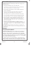
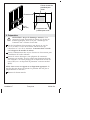
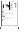
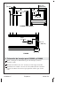
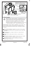
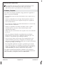
5. Secure the Vanity
CAUTION: Risk of property damage. Select 500 lb (227 kg)
load bearing 5/16″ lag bolts with a length to clear obstacles
in the wall and 5/16″ washers. Calculate proper lag bolt
length by adding the following: 1-1/2″ (38 mm) backing
material + wallboard thickness + back rail thickness.
CAUTION: Risk of product damage. Drill the lag bolt pilot holes
in the ends of the back rail to provide maximum support and to
prevent flexing of the unit.
Wall-hung vanity only: Using 2x4 lumber, create a temporary
support that is 14-3/4″ (375 mm) in height and spans the width
of the vanity.
With assistance, lift and place the vanity in position against the
finished wall.
Verify the vanity is level and plumb against the wall.
Wall-hung vanity only: Place shims under the temporary support
to adjust the unit as needed.
Vanity with legs only: Turn the leveler(s) to adjust the unit as
needed.
Using a 1/4″ drill bit, drill a pilot hole at each end of the back
rail and into the finished wall. The holes should align with the
2x6 bracing or stud framing.
Drill a pilot hole at each stud location between the two end holes.
Washer
Lag Bolt
Back Rail
Temporary Support
(For Wall-Hung)
Leveler
Position lag bolts at ends of back rail
and secure into bracing.
2x6 Bracing
Pilot Hole
1216526-2-F 8 Kohler Co.

Secure the Vanity (cont.)
Secure the vanity to the wall with 5/16″ lag bolts and washers
(not provided). The lag bolts should engage the 2x6 bracing
and/or all studs behind the rail.
If used, remove and discard the temporary support once the
vanity is properly installed.
Install optional accessories (shelves, drawers, other) as desired.
Refer to the instructions packed with the accessories.
Kohler Co. 9 1216526-2-F

Adjust the Door
The hinges can be adjusted for proper door functionality and
alignment.
Refer to the illustration and note the screwdriver location for the
desired adjustment.
1216526-2-F 10 Kohler Co.

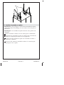
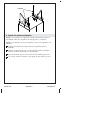
Remove the Door
Removal
With one hand, support the door in the open position.
Starting with the bottom hinge, press the latch at the end of the
hinge to release it from the bracket.
Repeat for the upper hinge.
Move the door forward to slide the hinges off the brackets.
Reinstallation
With one hand, support the door in the open position.
Starting with the top bracket, align the hinge pin with the cup of
the bracket.
Press the back of the hinge to snap the latch onto the bracket.
Repeat for the lower hinge.
Open and close the door to ensure proper operation.
Latch
Remove Reinstall
Pin
Cup
Kohler Co. 11 1216526-2-F

Remove/Adjust the Drawer
Alignment
To adjust the height and level the drawer, move the tabs
underneath the front corners back or forward as needed.
For fine adjustment, loosen the screws behind the drawer face,
then hold the drawer face level while retightening the screws.
Removal
Fully extend the drawer.
From underneath, press the release latches toward the sides of the
drawer.
Lift the front of the drawer to disengage from the rails.
Reinstallation
Fully extend the rails.
Align the holes in the back of the drawer with the rail hooks.
Rotate the drawer down onto the rails, engaging the latches with
the rails.
Push the drawer closed to fully engage the latches.
To ensure the drawer is properly engaged, lightly lift the front of
the drawer. If not engaged, repeat the ″Reinstallation″ procedure.
Hole
Rail
Tab
Screw
Bottom
of Drawer
1216526-2-F 12 Kohler Co.

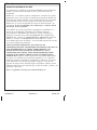
Care and Cleaning
For best results, keep the following in mind when caring for your
KOHLER product:
•
Blot spills immediately with a soft, damp cloth.
•
Test cleaners in a discrete location first, such as the inside of a
door, to ensure that there is no adverse reaction.
•
Do not expose wood furniture to direct sunlight, drying heat
sources, or dampness.
•
Protect wood surfaces by using felt, leather or cork under
accessories. Never slide objects across wood surfaces.
•
Dust frequently with a soft cloth in the direction of the grain.
•
Use only products specifically made for cleaning wood. Avoid
using oily polishes or waxes, or products containing silicone.
•
Every six months, remove soil buildup by rubbing with a soft
cloth dampened in a 50/50 solution of warm water and an
ammonia-free detergent. Wipe clean with a cloth dampened in
warm water. Wipe dry.
•
Paint pens and touch-up markers are available to conceal
scratches on the wood surface. These products may be purchased
from a Kohler distributor or call 1-800-4-KOHLER for ordering
information.
For detailed cleaning information and products to consider, visit
www.kohler.com/clean. To order Care & Cleaning information, call
1-800-456-4537.
Warranty
ONE-YEAR LIMITED WARRANTY
KOHLER plumbing products are warranted to be free of defects in
material and workmanship for one year from date of installation.
Kohler Co. will, at its election, repair, replace or make appropriate
adjustment where Kohler Co. inspection discloses any such defects
occurring in normal usage within one (1) year after installation. Kohler
Co. is not responsible for removal or installation costs. Use of in-tank
toilet cleaners will void the warranty.
To obtain warranty service contact Kohler Co. either through your
Dealer, Plumbing Contractor, Home Center or E-tailer, or by writing
Kohler Co., Attn.: Customer Care Center, 444 Highland Drive, Kohler,
Kohler Co. 13 1216526-2-F

Warranty (cont.)
WI 53044, USA, or by calling 1-800-4-KOHLER (1-800-456-4537) from
within the USA and Canada, and 001-800-456-4537 from within Mexico,
or visit www.kohler.com within the USA, www.ca.kohler.com from
within Canada, or www.mx.kohler.com in Mexico.
IMPLIED WARRANTIES INCLUDING THAT OF
MERCHANTABILITY AND FITNESS FOR A PARTICULAR
PURPOSE ARE EXPRESSLY LIMITED IN DURATION TO THE
DURATION OF THIS WARRANTY. KOHLER CO. AND/OR
SELLER DISCLAIM ANY LIABILITY FOR SPECIAL, INCIDENTAL
OR CONSEQUENTIAL DAMAGES. Some states/provinces do not
allow limitations on how long an implied warranty lasts, or the
exclusion or limitation of special, incidental or consequential damages,
so these limitations and exclusions may not apply to you. This
warranty gives you specific legal rights. You may also have other
rights which vary from state/province to state/province.
This is Kohler Co.’s exclusive written warranty.
1216526-2-F 14 Kohler Co.

Guide d’installation et d’entretien
Meuble de toilette
Outils et matériel
Avant de commencer
ATTENTION: Risque de dommages matériels. Choisir des
tire-fonds de 5/16″ porteurs de 500 lb (227 kg) avec une
longueur adéquate pour dégager les obstacles dans le mur,
ainsi que des rondelles de 5/16″. Calculer une longueur de
tire-fonds adéquate en ajoutant les valeurs suivantes:
matériau de renfort de 1-1/2″ (38 mm) + épaisseur de
panneau mural + épaisseur de rail arrière.
IMPORTANT! Risque d’endommagement du produit. Ne pas
modifier le meuble de toilette. Ceci pourrait compromettre la
stabilité structurelle.
AVIS: Du mastic à l’acrylique siliconisé doit être utilisé pour
sécuriser un lavabo ou un comptoir sur le meuble. Ne pas utiliser de
mastic à la silicone à 100%, car cela endommagera la finition du
meuble.
AVIS: Tous les composants électriques doivent être raccordés à un
circuit protégé par un disjoncteur de fuite de terre (GFCI) ou à un
dispositif de protection à courant résiduel (RCD). Respecter tous les
codes électriques locaux.
Plus:
• Vis à bois
• 2x6, 2x4 (Optionnels)
• Tire-fond 5/16" et rondelles
[Porteur min 500 lb (227 kg)]
• Clés à douille
• Couteaux latéraux
Kohler Co. Français-1 1216526-2-F

Avant de commencer (cont.)
Le produit en question peut être différent de celui qui est illustré.
Les procédures d’installation restent les mêmes.
Respecter tous les codes de construction locaux.
Deux personnes doivent installer ce produit.
Fixer le meuble de toilette sur l’ossature. Lorsque possible, fournir
une entretoise 2x6 à l’arrière du mur fini pour fournir un support
supplémentaire.
Ce meuble de toilette est conçu pour permettre à la plupart des
moulures de base de passer derrière le meuble de toilette.
Pour faciliter l’installation, retirer les tiroirs du meuble de toilette
avant de commencer. Se reporter à la section dans ce guide pour
une dépose appropriée.
1216526-2-F Français-2 Kohler Co.

1. Pose de visserie pour le modèle K-99688
Mesurer et marquer les dimensions pour la visserie comme sur
l’illustration ci-dessus.
Percer un trou de 3/16″ (21 mm) au niveau de chaque repère.
Enfiler une vis par chaque trou à partir de l’intérieur. Compter le
nombre d’encoches visibles à partir de l’autre côté.
Retirer la vis. Couper la vis à l’encoche appropriée en utilisant un
couteau latéral. Répéter pour toutes les vis.
Insérer une vis à travers chaque trou et les aligner sur les
poignées. Visser les vis dans les poignées.
Emplacement de
bouton de tiroir
Emplacement de
bouton de porte
1-1/2" (38 mm)
3"
(76 mm)
3" (76 mm)
2-1/8"
(54 mm)
3" (76 mm)
Centré
Côte à côte
Kohler Co. Français-3 1216526-2-F

2. Pose de visserie pour les modèles K-99686 et K-99689
Mesurer et marquer les dimensions pour la visserie comme sur
l’illustration ci-dessus.
Percer un trou de 3/16″ (21 mm) au niveau de chaque repère.
Enfiler une vis par chaque trou à partir de l’intérieur. Compter le
nombre d’encoches visibles à partir de l’autre côté.
Retirer la vis. Couper la vis à l’encoche appropriée en utilisant un
couteau latéral. Répéter pour toutes les vis.
1"
(25 mm)
4-5/8"
(117 mm)
K-99686 and K-99689
3" (76 mm)
4-5/8"
(117 mm)
Centré
Côte à côte
K-99689
4-5/8"
(117 mm)
3" (76 mm)
4-1/4"
(108 mm)
1216526-2-F Français-4 Kohler Co.

Pose de visserie pour les modèles K-99686 et K-99689 (cont.)
Insérer une vis à travers chaque trou et les aligner sur les
poignées. Visser les vis dans les poignées.
Kohler Co. Français-5 1216526-2-F

3. Préparation
ATTENTION: Risque de dommages matériels. Pour
supporter le poids du meuble de toilette et le lavabo de
manière appropriée, fixer sur le pan à colombages ou
l’entretoise 2x6 à l’arrière du mur fini.
Lors de l’installation d’une entretoise 2x6, placer un cran de
1-1/2″ (38 mm) à l’avant des montants afin d’assurer que
l’entretoise est à ras de ces montants. L’entretoise doit s’étendre
sur la longueur du meuble de toilette.
Prévoir l’acheminement des tuyaux d’arrivée et d’évacuation pour
l’installation de lavabo souhaitée.
Prévoir le service électrique si une plaquette de connexions
électriques est installée. Tous les composants électriques doivent
être raccordés à un circuit protégé par un disjoncteur de fuite de
terre (GFCI) ou à un dispositif de protection à courant résiduel
(RCD).
AVIS: Pour assurer un support et un alignement appropriés: Le
mur fini doit être droit et d’aplomb. Le plancher doit être plat et
perpendiculaire au mur fini.
Terminer la finition murale.
34-1/2"
(876 mm)
Entretoise 2x6
Prévoir la zone de
plomberie pour
l'évier.
L'apparence des
produits peut varier.
1216526-2-F Français-6 Kohler Co.
La page est en cours de chargement...
La page est en cours de chargement...
La page est en cours de chargement...
La page est en cours de chargement...
La page est en cours de chargement...
La page est en cours de chargement...
La page est en cours de chargement...
La page est en cours de chargement...
La page est en cours de chargement...
La page est en cours de chargement...
La page est en cours de chargement...
La page est en cours de chargement...
La page est en cours de chargement...
La page est en cours de chargement...
La page est en cours de chargement...
La page est en cours de chargement...
La page est en cours de chargement...
La page est en cours de chargement...
La page est en cours de chargement...
La page est en cours de chargement...
La page est en cours de chargement...
La page est en cours de chargement...
La page est en cours de chargement...
La page est en cours de chargement...
-
 1
1
-
 2
2
-
 3
3
-
 4
4
-
 5
5
-
 6
6
-
 7
7
-
 8
8
-
 9
9
-
 10
10
-
 11
11
-
 12
12
-
 13
13
-
 14
14
-
 15
15
-
 16
16
-
 17
17
-
 18
18
-
 19
19
-
 20
20
-
 21
21
-
 22
22
-
 23
23
-
 24
24
-
 25
25
-
 26
26
-
 27
27
-
 28
28
-
 29
29
-
 30
30
-
 31
31
-
 32
32
-
 33
33
-
 34
34
-
 35
35
-
 36
36
-
 37
37
-
 38
38
-
 39
39
-
 40
40
-
 41
41
-
 42
42
-
 43
43
-
 44
44


dans d''autres langues
- English: Kohler 99543-L-1WJ Installation guide
- español: Kohler 99543-L-1WJ Guía de instalación
Documents connexes
-
Kohler K-99542-1WA-2781-8-G81-99688-HF1 Guide d'installation
-
Kohler 99544SD1WKSTONE Mode d'emploi
-
-
Kohler K-99522-LG-1WA Mode d'emploi
-
Kohler 99514TK1WD996 Mode d'emploi
-
-
-
Kohler 99533-LGR-1WA Manuel utilisateur
-
-
Kohler K-R20199-1WA Mode d'emploi