Hestan KRT304NG Le manuel du propriétaire
- Catégorie
- Cuisinières
- Taper
- Le manuel du propriétaire
Ce manuel convient également à

INDOOR COOKING
Professional Rangetop
KRT
Installation Manual

SAFETY DEFINITIONS
THIS INDICATES THAT DEATH OR SERIOUS INJURY MAY OCCUR
AS A RESULT OF NOT OBSERVING THIS WARNING.
THIS INDICATES THAT MINOR OR MODERATE INJURY MAY
OCCUR AS A RESULT OF NOT OBSERVING THIS WARNING.
THIS INDICATES THAT DAMAGE TO THE APPLIANCE OR
PROPERTY MAY OCCUR AS A RESULT OF NOT OBSERVING THIS
WARNING.
READ THESE INSTRUCTIONS CAREFULLY AND COMPLETELY BEFORE
INSTALLING OR USING YOUR APPLIANCE TO REDUCE THE RISK OF FIRE,
BURN HAZARD, OR OTHER INJURY. KEEP THIS MANUAL FOR FUTURE
REFERENCE.
CAUTION
NOTICE
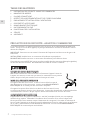
Do not store or use gasoline or other flammable vapors and liquids in the vicinity of
this or any other appliance.
WHAT TO DO IF YOU SMELL GAS:
1. Do not try and light any appliance.
2. Do not touch any electrical switch.
3. Do not use any phone in your building.
4. Immediately call your gas supplier from a neighbor’s phone. Follow the gas supplier’s
instructions.
5. If you cannot reach your gas supplier, call the fire department.
Installation and service must be performed by a qualified installer, service agency, or the gas
supplier.
IF THE INFORMATION IN THIS MANUAL IS NOT FOLLOWED EXACTLY,
A FIRE OR EXPLOSION MAY RESULT CAUSING PROPERTY DAMAGE,
PERSONAL INJURY, OR DEATH.
INSTALLER: LEAVE THIS MANUAL WITH THE OWNER OF THE APPLIANCE.
HOMEOWNER: RETAIN THIS MANUAL FOR FUTURE REFERENCE.

©2019 Hestan Commercial Corporation
1
EN
When properly cared for, your Hestan appliance will provide safe, reliable service for many years.
When using this appliance, basic safety practices must be followed as outlined below.
IMPORTANT: Save these instructions for the local Gas or Utility Inspector’s use.
INSTALLER: Please leave these Installation Instructions with the owner.
OWNER: Please retain these Installation Instructions for future reference.
This rangetop is NOT designed for installation in manufactured (mobile) homes or recreational park
trailers. Do NOT install this rangetop outdoors.
SAFETY PRECAUTIONS - BEFORE YOU BEGIN
ELECTRICAL SHOCK HAZARD
Disconnect power before installing or servicing appliance. Before turning power
ON, be sure all controls are in the OFF position. Failure to do so can result in
electrical shock or death.
ELECTRICAL GROUNDING
This appliance must be grounded. Grounding reduces the risk of electric shock in
the event of a short circuit. Read the ELECTRICAL CONNECTIONS section of
this manual for complete instructions.
This appliance is equipped with a 3-prong grounding plug for your protection against shock hazard
and should be directly plugged into a properly grounded receptacle. Do not cut or remove the
grounding prong from this plug.
ELECTRICAL SUPPLY
The appliance must be on its own dedicated circuit - 120 VAC, Single Phase, 60 Hz, with a current
rating of 15 Amps. Have the installer show you where the electric circuit breaker is located so
you know how to shut off the power to this appliance. It is the responsibility of the user to have
the appliance connected by a licensed electrician in accordance with all local codes, or in the
absence of local codes, in accordance with the National Electrical Code. Read the ELECTRICAL
CONNECTIONS section of this manual for complete details.
TABLE OF CONTENTS
1 SAFETY PRECAUTIONS - BEFORE YOU BEGIN
2 MODEL NUMBERS
3 RATING LABEL
3 REGULATORY / CODE REQUIREMENTS
3 LOCATION AND INSTALLATION / VENTILATION
7 BACKGUARD AND ACCESSORIES
8 ELECTRICAL CONNECTIONS
8 GAS CONNECTION
10 FINAL SETUP
12 SERVICE
12 APPENDIX

©2019 Hestan Commercial Corporation
2
EN
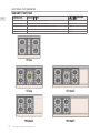
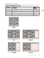
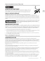
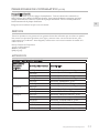
MODEL NUMBERS
RANGETOP MODELS
MODEL NO. DESCRIPTION
CIRCUIT BREAKER
REQUIRED
KRT304-NG / -LP 30” RANGETOP WITH 4 BURNERS 15 Amp
KRT365-NG / -LP 36” RANGETOP WITH 5 BURNERS 15 Amp
KRT364GD-NG / -LP 36” RANGETOP WITH 4 BURNERS & GRIDDLE 15 Amp
KRT485GD-NG / -LP 48” RANGETOP WITH 5 BURNERS & 12” GRIDDLE 15 Amp
KRT484GD-NG / -LP 48” RANGETOP WITH 4 BURNERS & 24” GRIDDLE 15 Amp
KRT365
KRT304
KRT485GD
KRT364GD KRT484GD

©2019 Hestan Commercial Corporation
3
EN
REGULATORY / CODE REQUIREMENTS
Installation of this cooking appliance must be made in accordance with local codes. In the absence
of local codes, this unit should be installed in accordance with the National Fuel Gas Code
ANSI
Z223.1/NFPA 54
, Natural Gas and Propane Installation code
CSA B149.1
, or Propane Storage and
Handling Code
B149.2
.
All Electrical Components must be electrically grounded in accordance with local codes or in the
absence of local codes with the National Electrical Code
ANSI/NFPA 70
, or Canadian Electrical code
CSA C22.1
.
STATE OF MASSACHUSETTS
Massachusetts requires all gas be installed using a plumber or gas fitter carrying the appropriate
Massachusetts license. All permanently installed natural gas or propane installations require a
T handle type manual gas valve be installed in the gas supply line to this appliance. Flexible gas
connector must not be longer than 36” [91.4 cm].
CALIFORNIA PROPOSITION 65 - WARNING
WARNING This product can expose you to chemicals including carbon monoxide, which is
known to the State of California to cause birth defects or other reproductive harm.
For more information, go to www.P65Warnings.ca.gov.
RATING LABEL
The rating label contains important information about your
Hestan appliance such as the model and serial number,
gas type and manifold pressure, electrical rating, the BTU
rating for each burner type, and the minimum installation
clearances.
The rating label is located underneath the unit.
If service is necessary, contact Hestan Customer Care with
the model and serial number information shown on the label.
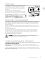
LOCATION AND INSTALLATION / VENTILATION
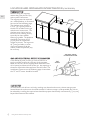
UNPACKING AND PLACEMENT
Remove the outer carton and packing materials. Do not remove the plastic film covering the
stainless-steel surfaces. This film protects the finish from scratches until the appliance is installed in
its final position.
The unit is somewhat heavy and should be handled with care. Use proper safety equipment, such as
gloves, and at least 2 persons to move the appliance into position to avoid injury and to avoid damage
to the floor or the appliance itself.
RATING
LABEL

©2019 Hestan Commercial Corporation
4
EN
LOCATION AND INSTALLATION/VENTILATION
(CONTINUED)
GAS
SUPPLY
TO
APPLIANCE
SHUTOFF VALVE
IN OPEN POSITION
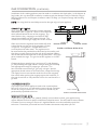
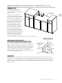
PREPARATION
Before moving the rangetop,
remove the grates, burner caps,
and any other loose items.
The rangetop must be mounted
on a stable platform, as illustrated
here and on the following pages.
The platform must include a
6” x 12” [15 x 30 cm] cutout at
the left rear to allow for the gas
and electrical connections. The
platform must also be level to
ensure an even cooking surface,
especially for those models
featuring a griddle. The platform
should be a minimum of 3/4”
[19 cm] thick to support the
weight of the unit. For large units
48” [1.2m] and wider, a center
structural element inside the
cabinet, under the platform, may
be necessary.
GAS AND ELECTRICAL SUPPLY CLEARANCES
If not already in place, install a gas shut-off valve in an
easily accessible location for servicing of the rangetop.
Make sure all users of the rangetop know where this shut-
off is located, and how to shut off the gas. Any openings in
the wall or floor behind the appliance must be sealed. The
Installation Clearances on the following pages show where
the “G” and “E” zones should be located.
CABINETRY
To eliminate the risk of burns or fire by reaching over heated surface units, cabinet storage space
located above the surface units should be avoided. If cabinet storage is to be provided, the risk can
be reduced by installing the required vent hood that projects horizontally a minimum of 5” [12.7 cm]
beyond the bottom of the cabinets.
12
[30]
6
[15]
3/4" THICK
PLATFORM

©2019 Hestan Commercial Corporation
5
EN
LOCATION AND INSTALLATION/VENTILATION
(CONTINUED)
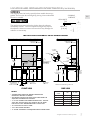
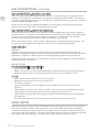
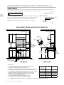
INSTALLATION CLEARANCES WITH LOW BACKGUARD
DIMENSIONS IN BRACKETS [ ] ARE IN CM.
18” [45.7]
MIN.
W
V
12”
[30.5]
9-1/2”
[24.1]
28-1/2”
[72.4]
10”
[25.4]
2”
[5.1]
7-1/2” [19] MAX.
OPENING
HEIGHT
RECOMMENDED
GAS SHUT-OFF
VALVE LOCATION
FINISHED
FLOOR
VENT HOOD
MIN. CLEARANCE
TO NEAREST
COMBUSTIBLE
SIDE SURFACE
G
E
ELECTRICAL
SUPPLY
LOCATION
PLATFORM
COMBUSTIBLE
MATERIALS
FRONT VIEW
APPLIANCE
TOP
COOKING
SURFACE
71.6
13” [33]
MAX.
37-1/8”
[94.3]
TO COOKING
SURFACE
28-1/2”
[72.4]
24-1/2” [62] MAX.
PLATFORM
7-1/2” [19]
MAX.
OPENING
HEIGHT
LOW
BACKGUARD
COMBUSTIBLE
MATERIALS
SIDE VIEW
28-3/16”
LEVELING
The rangetop must be level, especially those models featuring a
griddle. Raise to the desired height by placing shims underneath
the unit as needed.
CAUTION
The appliance top must be level or higher than the adjacent
countertop surfaces. Failure to adjust the height may expose
the adjacent cabinets to excessive heat which may damage the
cabinets or countertop.
REF 1.12”
[2.84 cm]
COOKING
SURFACE
APPLIANCE
TOP
REF 1.12”
[2.84 cm]
RANGETOP
MODEL
W
V (MIN)
KRT304 30” [76.2] 30” [76.2]
KRT365 36” [91.4] 30” [76.2]
KRT364GD 36” [91.4] 30” [76.2]
KRT485GD 48” [121.9] 30” [76.2]
KRT484GD 48” [121.9] 30” [76.2]
NOTES:
*
SHADED AREAS INDICATE WHERE COMBUSTIBLE
MATERIALS ARE NOT ALLOWED.
*
APPLIANCE TOP MUST BE LEVEL OR HIGHER THAN THE
ADJACENT COUNTERTOP SURFACES.
*
"G" IS GAS CONNECTION ZONE ON REAR WALL. MOUNT
SHUT-OFF VALVE AS HIGH AS
POSSIBLE IN THIS ZONE
FOR EASY ACCESS WHEN RANGETOP IS INSTALLED.
*
"E" IS ELECTRICAL SUPPLY ZONE.
*
"W" IS APPLIANCE OPENING.
*
"V" IS MIN. CLEARANCE TO REQUIRED VENTILATION HOOD.

©2019 Hestan Commercial Corporation
6
EN
LOCATION AND INSTALLATION/VENTILATION
(CONTINUED)
W
9-1/2”
[24.1]
2”
[5.1]
V
12”
[30.5]
28-1/2”
[72.4]
10”
[25.4]
7-1/2” [19] MAX.
OPENING
HEIGHT
RECOMMENDED
GAS SHUT-OFF
VALVE LOCATION
ELECTRICAL
SUPPLY
LOCATION
G
FINISHED
FLOOR
MIN. CLEARANCE
TO NEAREST
COMBUSTIBLE
SIDE SURFACE
E
PLATFORM
COMBUSTIBLE
MATERIALS
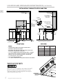
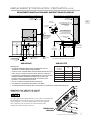
INSTALLATION CLEARANCES WITH ISLAND TRIM
FRONT VIEW
DIMENSIONS IN BRACKETS [ ] ARE IN CM.
COMBUSTIBLE
MATERIALS
12”
[30.5]
28-1/2”
[72.4]
24-1/2” [62] MAX.
PLATFORM
7-1/2” [19]
MAX.
OPENING
HEIGHT
[71.6]
37-1/8”
[94.3]
TO COOKING
SURFACE
ISLAND
TRIM
For Island Trim installations,
counter surface should
have a cantilever surface
meeting the rear of
the Island Trim
MIN. CLEARANCE
TO COMBUSTIBLE
SURFACES WITH
ISLAND TRIM
COOKING
SURFACE
APPLIANCE
TOP
SIDE VIEW
28-3/16”
FRONT COOLING VENTS
NOTICE
When placing your rangetop in the cabinet, DO NOT
BLOCK or obstruct the front cooling vents shown.
These vents allow air into the appliance to keep the
internal electronic parts cool.
COOLING
VENTS
RANGETOP
MODEL
W
V (MIN)
KRT304 30” [76.2] 30” [76.2]
KRT365 36” [91.4] 30” [76.2]
KRT364GD 36” [91.4] 30” [76.2]
KRT485GD 48” [121.9] 30” [76.2]
KRT484GD 48” [121.9] 30” [76.2]
NOTES:
*
SHADED AREAS INDICATE WHERE COMBUSTIBLE
MATERIALS ARE NOT ALLOWED.
*
APPLIANCE TOP MUST BE LEVEL OR HIGHER THAN THE
ADJACENT COUNTERTOP SURFACES.
*
"G" IS GAS CONNECTION ZONE ON REAR WALL. MOUNT
SHUT-OFF VALVE AS HIGH AS
POSSIBLE IN THIS ZONE
FOR EASY ACCESS WHEN RANGETOP IS INSTALLED.
*
"E" IS ELECTRICAL SUPPLY ZONE.
*
"W" IS APPLIANCE OPENING.
*
"V" IS MIN. CLEARANCE TO REQUIRED VENTILATION HOOD.

©2019 Hestan Commercial Corporation
7
EN
LOCATION AND INSTALLATION/VENTILATION
(CONTINUED)
BACKGUARD AND ACCESSORIES
Sheetmetal accessories such as the backguard, and areas at the rear of the rangetop may have sharp
edges. Wear work gloves while handling and installing these items.
BACKGUARD
Your Hestan rangetop is supplied at the factory with an Island Trim backguard. See Table 1 in the
APPENDIX section of this manual for other backguard options available from your Hestan dealer.
Selection of the appropriate backguard depends on the installation location and adjacent materials,
and the type of vent hood to be used. Installation instructions are included with the backguard kit.
A LOW OR TALL BACKGUARD IS REQUIRED WHEN INSTALLING THE RANGETOP AGAINST A
COMBUSTIBLE SURFACE - THE ISLAND TRIM IS NOT SUITABLE.
The top of the backguard serves as an exhaust vent to remove heat from under the rangetop. DO
NOT BLOCK or obstruct the top of the backguard. DO NOT touch the top of the backguard during
appliance operation as it may get hot. Allow sufficient time to cool before touching or cleaning this
area. DO NOT position plastic or other heat-sensitive items nearby which could melt or burn.
CAUTION
CAUTION
VENTILATION REQUIREMENTS
It is strongly recommended that this appliance be installed with a Hestan vent hood. Due to the high
heat output of this rangetop, it is very important that the hood and ductwork installation meets local
building codes and is installed by a qualified technician.
Do not use a down-draft style ventilation system.
Do not mount a microwave oven/ventilator combination above the rangetop. These type of units do
not have sufficient airflow to remove the high heat output of this rangetop and were not tested with
this type of appliance.
For non-Hestan approved vent hoods, the vent hood and/or blower unit must be rated for 1 CFM
[1.7 m³/hr] for every 100 BTU [.03 kW].
• If the rangetop has a 12” Griddle, add an additional 200 CFM [340 m³/hr] to the blower capacity.
• If the rangetop has a 24” Griddle, add an additional 400 CFM [680 m³/hr] to the blower capacity.
For island applications, it is recommended to use a vent hood that is 6” [15.2 cm] wider than the
appliance, to allow for 3” [7.6 cm] of overlap on the left and right of the appliance.
Keep duct runs as short and straight as possible. Elbows and transition fittings reduce airflow
efficiency. Hestan recommends keeping the duct run under 50 ft. [15.2 m].
CONSULT WITH YOUR HESTAN DEALER ON SELECTING THE APPROPRIATE
VENT HOOD FOR YOUR HESTAN APPLIANCE.

©2019 Hestan Commercial Corporation
8
EN
ELECTRICAL CONNECTIONS
ELECTRICAL SHOCK HAZARD
Disconnect power before installing or servicing appliance. Before turning power
ON, be sure all controls are in the OFF position. Failure to do so can result in
electrical shock or death.
ELECTRICAL GROUNDING
This appliance must be grounded. Grounding reduces the risk of electric shock in
the event of a short circuit. Grounding through the neutral conductor is prohibited for new branch
circuit installations (1996 NEC), mobile homes, and recreational vehicles, or in an area where local
codes prohibit it. Your Hestan rangetop is equipped with a 3-prong, grounding type plug which must
be plugged into a grounded, 3-prong 120V receptacle.
CAUTION
Improper grounding or reverse polarization will cause malfunctions in the
unit, such as continuous sparking of the igniters. This can damage the
appliance and create a shock hazard condition.
ELECTRICAL CONNECTION
The receptacle must be on its own dedicated circuit - 120 VAC, Single Phase, 60 Hz, with a current
rating of 15 Amps. If this is not available, a licensed electrician must install the appropriately
dedicated and grounded receptacle. The installation must be done in accordance with local codes,
or in the absence of local codes, it must be installed in accordance with the National Electrical Code,
ANSI/NFPA 70.
1. Make sure power is off at the supply panel / breaker.
2. Plug the appliance into the wall receptacle. Secure extra appliance cord out of the way so it
cannot be snagged on items under your rangetop.
3. Before restoring power at the supply panel / breaker, be sure all controls are in the OFF position.
GAS CONNECTION
GAS SUPPLY
The local gas authority or supplier should be consulted at the installation planning stage in order to
establish the availability of an adequate supply of gas (NG or LP). If it is a new installation, have the
gas authorities or supplier check the meter size and piping to assure that the unit is supplied with the
necessary amount of gas supply and pressure to operate the unit(s).
Gas connections should be made by a qualified plumber, or your professional appliance installer.
All appliances must be fitted with an accessible upstream gas shutoff valve as a means of isolating the
appliance for emergency shut off and for servicing.
Make certain new piping and connections have been made in a clean manner and have been purged
so that piping compound, chips, etc. will not clog regulators, valves, orifices, or burners. Use pipe
joint compound / thread sealant approved for natural and LP gases.
The appliance and its individual manual shutoff valve must be disconnected from the gas supply
piping system during any pressure testing of that system at test pressures in excess of 1/2 psi
[3.5kPa].
The appliance must be isolated from the gas supply piping system by closing its individual manual
shutoff valve during any pressure testing of that system at test pressures equal to or less than 1/2 psi
[3.5kPa].
NEVER CONNECT THE APPLIANCE TO AN UNREGULATED GAS SUPPLY. Before proceeding,
ensure the appliance is fitted for Natural or Liquid Propane gas. Connecting to an improper gas type
will result in poor performance and increased risk of damage or injury. Gas type and gas consumption
(BTU per hour) for each burner type is shown on the rating label.

©2019 Hestan Commercial Corporation
9
EN
Installation of this cooking appliance must be made in accordance with local codes. In the absence of
local codes, this unit should be installed in accordance with the National Fuel Gas Code No.
Z223.1/
NFPA 54
, Natural Gas and Propane Installation code
CSA B149-1
, or Propane Storage and Handling
Code B149.2.
NOTE: See rating label for manifold pressure for the type of gas of your appliance.
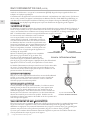
CONNECTING THE GAS
Some rangetop units may have the regulator mounted
internally as seen in Figure A. There is a short flex hose
which extends below the rear of the rangetop. This
short flex hose has a connection end with 1/2”NPT
internal thread AND 3/4”NPT external threads. The
installer must connect a gas supply hose at this location.
Other units have the regulator located externally with
a short flex hose at the rear of the rangetop as shown
in Figure B. The regulator is shipped loose in the
accessory box with other items. The regulator must
be connected to the provided short flex hose by the installer, and
then the gas supply hose to the inlet side of the regulator. Make a
note of the flow arrow embossed on the regulator itself. The arrow
points toward the range. The gas inlet of the regulator is 1/2”NPT
thread.
Connect to the gas supply using a mininum 3/4” inside diameter
(1”OD) flexible (semi-rigid) stainless steel gas hose (not included)
with appropriate fittings to prevent gas starvation. This
hose should be no more that 36” [91.4 cm] in length. Use the
appropriate thread sealant on all connections, except flare fittings.
The supply line must not interfere with the rear of the rangetop.
Use caution when pushing the rangetop against the back wall, so
that you do not kink or crimp the flex hose as this could result in a
gas leak.
CONVERSION KITS
In the event your Hestan appliance needs to be converted from
NG to LP, or vice-versa, you will need to contact Hestan Customer
Service to arrange a service call. This conversion should only be
performed by a qualified technician.
HIGH ALTITUDE KITS
If you live in a high altitude area, 2,000 ft. [610 m] or more above sea level, your appliance may
require different orifices for proper combustion and performance. You will need to contact Hestan
Customer Service to arrange a service call. High Altitude kits must be installed by a qualified
technician. Please have your model and serial number information ready when you call.
1/2”NPT
INTERNAL THREAD
FIGURE A: INTERNAL REGULATOR
3/4”NPT
EXTERNAL THREAD
1/2” NPT THREAD
FIGURE B: EXTERNAL REGULATOR
GAS CONNECTION
(CONTINUED)

©2019 Hestan Commercial Corporation
10
EN
GAS CONNECTION
(CONTINUED)
GAS CONNECTION - NATURAL GAS (NG)
To ensure proper heating performance of this appliance, verify that the gas line supply pressure is
adequate. The appliance is supplied with a gas pressure regulator already installed. This regulator
is set for a supply (inlet) pressure of 7-14 inch WC [1.74-3.48 kPa] to maintain 5 inch WC [1.24 kPa]
nominal outlet (manifold) pressure.
Ensure that the service pipe supplying the appliance is fitted with a shut-off valve conveniently
positioned and easily accessible as an emergency gas shut-off.
GAS CONNECTION - LIQUID PROPANE (LP)
If you purchased an LP version of your appliance, it will be supplied with a gas pressure regulator
already installed. This regulator is set to maintain 10 inch WC [2.49 kPa] nominal outlet (manifold)
pressure. Ensure that the service pipe supplying the appliance is fitted with a shut-off valve
conveniently positioned and easily accessible as an emergency gas shut-off.
When connecting to LP gas, verify the tank is equipped with its own high pressure regulator. The
pressure of the gas supplied to the appliance must be 11-14 inch WC [2.74-3.48 kPa].
LEAK TESTING
GENERAL
Although all gas connections on your Hestan appliance are leak tested at the factory prior to
shipment, a complete gas tightness check must be performed at the installation site due to possible
movement in shipment, or excessive pressure unknowingly being applied to parts of the unit.
Immediately check if the smell of gas is detected. Leak testing of the appliance shall be conducted
according to these instructions:
BEFORE TESTING
DO NOT SMOKE WHILE LEAK TESTING.
• Never leak test with an open flame.
• Make a soap solution of one part liquid detergent and one part water for leak testing purposes.
• Apply the solution to the gas fittings and flex hose by using a spray bottle or a brush.
TO TEST
• Make sure all control knobs are in the “OFF” position.
• Apply the soap solution to all fittings and flex hose.
• Turn the gas supply on.
• Check all connections from the supply line up to regulator connection at the rear of the
appliance.
• Soap bubbles will appear where a leak is present. If a leak is present, immediately turn off gas
supply, tighten any leaking fittings, turn the gas supply back on, and recheck.
• If you cannot stop a gas leak, turn off the gas supply and call the dealer where you purchased
your appliance.
• Do not use the appliance until all connections have been checked and do not leak.
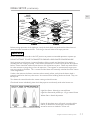
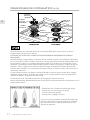
FINAL SETUP
Remove any final packaging materials, and protective film from all exterior areas. Install any loose
items like sealed burner heads, cooking grates, etc. Ensure the sealed burner heads are properly
installed and seated on the burner base as shown below. There are notches on the burner base and
cross ring to help with alignment. The outer burner head features a long slot on the top of the head
which aligns with the spark igniter. Assembly of the single-flow burner head is similar.

©2019 Hestan Commercial Corporation
11
EN
FINAL SETUP
(CONTINUED)
Before testing operation of the appliance, verify the leak check was performed and the electrical
power has been restored to the unit. Turn the gas shut-off valve to the open position.
NOTICE
All the control knobs must be in the OFF position to prevent unintended operation at power up.
DO NOT ATTEMPT TO USE THE RANGETOP DURING A PROLONGED POWER FAILURE.
Verify ignition at each burner. Igniter will make a clicking sound until the flame lights within 4
seconds, then the clicking will stop. Check flame characteristics at each burner per the descriptions
below. Flames should be stable and not dance or lift off the burner ports. Flame may need to burn
for a few minutes to purge the gas lines of impurities. These appear as intermittent orange tips or
even tiny sparks in the flame. This is normal and the flame will eventually stabilize like those shown
in the image below.
If after a few minutes the flames continue to burn mostly yellow, verify that the burner head is
properly installed on the base, then retest. Use caution when handling the burner heads. They can
be very hot.
Turn down the control knob to the simmer setting to check function.
Check each burner individually, then check they operate satisfactorily with other burners on.
Light blue flame - Natural gas normal flame
Light blue flame with yellow tips - LP gas normal flame
Yellow flame - Needs adjustment
If after all the above tests still result in mostly yellow
flames, or the burners do not light, contact Hestan
customer service to schedule a service call.
BURNER
RING
BURNER
HEAD
BURNER
BASE
IGNITER
INNER
BURNER
HEAD
OUTER
BURNER
HEAD
BEAUTY
RING
CROSS
RING
BURNER
BASE
DUAL FLOW
BURNER
SINGLE FLOW
BURNER

©2019 Hestan Commercial Corporation
12
EN
APPENDIX
TABLE 1 - BACKGUARD OPTIONS
RANGE MODEL BACKGUARD MODEL DESCRIPTION
KRT304 KBGIT30* BACKGUARD, ISLAND TRIM, 30”
KBGLB30 BACKGUARD, LOW BACK, 30”
KBGHS30 BACKGUARD, HIGH SHELF, 30”
KRT365 KBGIT36* BACKGUARD, ISLAND TRIM, 36”
KBGLB36 BACKGUARD, LOW BACK, 36”
KBGHS36 BACKGUARD, HIGH SHELF, 36”
KRT364GD KBGIT36* BACKGUARD, ISLAND TRIM, 36”
KBGLB36 BACKGUARD, LOW BACK, 36”
KBGHS36 BACKGUARD, HIGH SHELF, 36”
KRT485GD KBGIT48* BACKGUARD, ISLAND TRIM, 48”
KBGLB48 BACKGUARD, LOW BACK, 48”
KBGHS48 BACKGUARD, HIGH SHELF, 48”
KRT484GD KBGIT48* BACKGUARD, ISLAND TRIM, 48”
KBGLB48 BACKGUARD, LOW BACK, 48”
KBGHS48 BACKGUARD, HIGH SHELF, 48”
SERVICE
All warranty and non-warranty repairs should be performed by qualified service personnel. To
locate an authorized service agent in your area, contact your Hestan dealer, local representative, or
Hestan. Before you call, please have the model number and serial number information on hand.
Hestan Commercial Corporation
3375 E. La Palma Avenue
Anaheim, CA 92806
(888) 905-7463
GAS GRIDDLE
The gas griddle does not have flame/burner adjustments. Turn the control knob to HIGH, verify that
the griddle heats up. You may also notice a constant orange glow at the rear vents of the griddle
area. This is normal during operation of the griddle.
Turn all burners off when testing is complete.
FINAL SETUP
(CONTINUED)

FR
DÉFINITIONS DE SÉCURITÉ
CECI INDIQUE QUE L’INOBSERVATION DE CET
AVERTISSEMENT PEUT ENTRAÎNER DES BLESSURES GRAVES
VOIRE MORTELLES.
CECI INDIQUE QUE L’INOBSERVATION DE CET
AVERTISSEMENT PEUT ENTRAÎNER DES BLESSURES
MINEURES OU MODÉRÉES.
CECI INDIQUE QUE L’INOBSERVATION DE CET
AVERTISSEMENT PEUT ENTRAÎNER DES DOMMAGES DE
L’APPAREIL OU DES DÉGÂTS MATÉRIELS.
LISEZ ATTENTIVEMENT ET COMPLÈTEMENT CES INSTRUCTIONS
AVANT D’INSTALLER OU D’UTILISER VOTRE APPAREIL AFIN DE RÉDUIRE
LES RISQUES D’INCENDIE, DE BRÛLURE OU D’AUTRES BLESSURES.
CONSERVER CE MANUEL POUR RÉFÉRENCE FUTURE.
PRÉCAUTION
AVIS
INSTALLATEUR: LAISSER CE MANUEL AVEC LE PROPRIÉTAIRE DE L’APPAREIL.
PROPRIÉTAIRE: CONSERVEZ CE MANUEL POUR RÉFÉRENCE FUTURE.
Ne pas entreposer ou utiliser d’essence ou tout autre liquide ou gaz inflammable à proximité de
cet appareil ou de tout autre appareil.
EN PRÉSENCE D’UNE ODEUR DE GAZ:
1. Ne tenter d’allumer aucun appareil.
2. Ne toucher à aucun commutateur électrique.
3. N’utiliser aucun téléphone dans l’immeuble.
4. Appeler immédiatement le fournisseur de gazà partir d’un téléphone situé à l’extérieur
del’immeuble. Suivre les instructions dufournisseur de gaz.
5. S’il est impossible de joindre le fournisseur degaz, appeler le service des incendies.
L ’installation et la réparation doivent être effectuées par un installateur ou une agence
deréparation ayant les qualifications requises oupar le fournisseur de gaz.
LE NON-RESPECT À LA LETTRE DE CES INSTRUCTIONS PEUT CAUSER
UN INCENDIE OU UNE EXPLOSION, QUI POURRAIT ENTRAÎNER DES
DOMMAGES MATÉRIELS, DES BLESSURES OU LA MORT.
©2018 Hestan Commercial Corporation

FR
© 2019 Hestan Commercial Corporation
1
S’il est bien entretenu, cet appareil Hestan procurera un service sûr et fiable pendant de nombreuses
années. Lorsqu’on se sert de cet appareil, les pratiques élémentaires suivantes en matière de sécurité
doivent être adoptées.
IMPORTANT: Conservez ces instructions à l’intention de l’Inspecteur local des services du gaz ou de
l’électricité.
INSTALLATEUR: Veuillez laisser ces instructions d’installation au propriétaire.
PROPRIÉTAIRE: Veuillez conserver ces instructions d’installation pour référence future.
Cette table de cuisson N’EST PAS conçue pour être installée dans des maisons préfabriquées (mobiles)
ou dans des véhicules récréatifs. N’installez PAS cette table de cuisson à l’extérieur.
PRÉCAUTIONS DE SÉCURITÉ - AVANT DE COMMENCER
RISQUE DE CHOC ÉLECTRIQUE
Débranchez l’alimentation avant d’installer ou d’entretenir l’appareil. Avant de
le mettre sous tension, assurez-vous que toutes les commandes sont en position
«OFF». Ne pas le faire peut entraîner un choc électrique ou la mort.
MISE À LA TERRE ÉLECTRIQUE
Cet appareil doit être mis à la terre. La mise à la terre réduit le risque de
choc électrique en cas de court-circuit. Lisez la section BRANCHEMENTS
ÉLECTRIQUES de ce manuel pour des instructions complètes.
Cet appareil est pourvu d’une fiche à trois broches don’t une mise à la terre
assurant une protection contre les chocs électriques. La prise dans laaquelle elle est branchée doit être
correctement mise à la terre. Ne pas couper ni enlever la broche de mise à la terre de la fiche.
ALIMENTATION ÉLECTRIQUE
L’appareil doit avoir son propre circuit distinct - 120 VAC, monophasé, 60 Hz, avec une ampérage
nominale de 15 ampères. Demandez à l’installateur de vous montrer où se trouve le disjoncteur
électrique afin de savoir comment couper l’alimentation de cet appareil. Il incombe à l’utilisateur de
faire raccorder l’appareil par un électricien agréé conformément à tous les codes locaux, ou en l’absence
de ces codes, conformément au Code National de l’Électricité. Lisez la section BRANCHEMENTS
ÉLECTRIQUES du cet manuel pour tous le détails.
TABLE DES MATIÈRES
1 PRÉCAUTIONS DE SÉCURITÉ - AVANT DE COMMENCER
2 NUMÉROS DE MODÈLE
3 PLAQUE SIGNALÉTIQUE
3 RESPECT DE LA RÉGLEMENTATION ET DES CODES EN VIGUEUR
3 EMPLACEMENT ET INSTALLATION / VENTILATION
7 DOSSERET ET ACCESSOIRES
8 BRANCHEMENTS ÉLECTRIQUES
8 RACCORDEMENT DE GAZ
10 PHASE FINALE DE L’INSTALLATION
12 SERVICE
12 APPENDICE

FR
© 2019 Hestan Commercial Corporation
2
NUMÉROS DE MODÈLE
MODÈLES DES TABLES DE CUISSON
NO. MODÈLE DESCRIPTION
DISJONCTEUR
REQUIS
KRT304-NG / -LP TABLE DE CUISSON 30 po À 4 BRÛLEURS 15 Ampères
KRT365-NG / -LP TABLE DE CUISSON 36 po À 5 BRÛLEURS 15 Ampères
KRT364GD-NG / -LP TABLE DE CUISSON 36 po À 4 BRÛLEURS ET PLAQUE CHAUFFANTE DE 12 PO 15 Ampères
KRT485GD-NG / -LP TABLE DE CUISSON 48 po À 5 BRÛLEURS ET PLAQUE CHAUFFANTE DE 12 PO 15 Ampères
KRT484GD-NG / -LP TABLE DE CUISSON 48 po À 4 BRÛLEURS ET PLAQUE CHAUFFANTE DE 24 PO 15 Ampères
KRT365
KRT304
KRT485GD
KRT364GD KRT484GD

FR
© 2019 Hestan Commercial Corporation
3
RESPECT DE LA RÉGLEMENTATION ET DES CODES EN VIGUEUR
L’installation de cet appareil de cuisson doit être effectuée conformément aux codes locaux. En l’absence
de tels codes, installer cet appareil conformément au National Fuel Gas Code ANSI Z223.1/NFPA 54, au
code Natural Gas and Propane Installation CSA B149.1 ou au Propane Storage and Handling Code B149.2.
Tous les composants électriques doivent mis à la terre conformément aux codes locaux ou, en l’absence de
tels codes, au National Electrical Code ANSI/NFPA 70 ou au Code national de l’électricité du Canada CSA
C22.1.
COMMUNAUTÉ DU MASSACHUSETTS
Le Communauté du Massachusetts exige que toutes les installations au gaz soient effectuées par
un plombier ou monteur d’installations au gaz titulaire d’une autorisation appropriée délivrée par le
Massachusetts. Toutes les installations à demeure fonctionnant au propane ou au gaz naturel exigent la
pose d’un robinet manuel de gaz à poignée en T sur la conduite d’alimentation en gaz de l’appareil. Le
tuyau de raccordement flexible de gaz ne doit pas dépasser 36 po [91.4 cm].
PROPOSITION 65 DE CALIFORNIE – MISE EN GARDE
AVERTISSEMENT Ce produit peut vous exposer à des produits chimiques, y compris le
monoxyde de carbone, qui est reconnu dans l’État de Californie pour causer des malformations
congénitales ou d’autres problèmes de reproduction.
Pour plus d’informations, visitez www.P65Warnings.ca.gov.
PLAQUE SIGNALÉTIQUE
La plaque signalétique donne des informations importantes sur
cet appareil Hestan telles que les numéros de série et de modèle,
le type de gaz et la pression d’admission, les caractéristiques
électriques, la cote BTU pour chaque type de brûleur et les
dégagements minima d’installation.
La plaque signalétique se trouve sous l’unité.
Si un entretien est nécessaire, contactez le service clientèle de
Hestan avec les informations sur le modèle et le numéro de série
figurant sur la plaque.
DÉBALLAGE ET PLACEMENT
Retirez le carton extérieur et les matériaux d’emballage de la palette d’expédition. Ne retirez pas le film
plastique recouvrant les surfaces en acier inoxydable. Ce film protège la finition contre les rayures jusqu’à
ce que l’appareil soit installé dans sa position finale.
L’unité est peu lourde et doit être manipulée avec soin. Utilisez un équipement de sécurité approprié,
tel que des gants, et au moins 2 personnes pour mettre l’appareil en position pour éviter les blessures et
éviter d’endommager le sol ou l’appareil lui-même.
EMPLACEMENT ET INSTALLATION / VENTILATION
PLAQUE SIGNALÉTIQUE

FR
© 2019 Hestan Commercial Corporation
4
EMPLACEMENT ET INSTALLATION / VENTILATION
(SUITE)
PRÉPARATION
Avant de déplacer la table de
cuisson, enlevez les grilles, les
chapeaux de brûleurs et tout autre
objet non fixé.
La table de cuisson doit être
montée sur une plate-forme stable,
tel qu’illustré ici et dans les pages
suivantes. La plate-forme doit
inclure une découpe de 6 po x 12 po
[15,2 x 30,5 cm] à l’arrière gauche
pour permettre les connexions
électriques et de gaz. La plate-
forme doit également être de
niveau pour garantir une surface
de cuisson uniforme, en particulier
pour les modèles dotés d’une
plaque chauffante. La plate-forme
doit avoir une épaisseur minimale
de 3/4po [19 cm] pour supporter le
poids de l’unité. Pour les grandes
unités de 48 po [1,2m] et plus,
un élément structurel central à
l’intérieur du meuble, sous la plate-forme, peut s’avérer nécessaire.
DÉGAGEMENTS DE GAZ ET
D’APPROVISIONNEMENT ÉLECTRIQUE
Si ce n’est pas déjà fait, posez un robinet d’arrêt de gaz
dans un endroit facilement accessible pour l’entretien de la
table de cuisson. Assurez-vous que tous les utilisateurs de
l’appareil savent où se trouve cette fermeture et comment
couper le gaz. Toute ouverture dans le mur ou le plancher
derrière l’appareil doit être scellée. Les dégagements
d’installation sur les pages suivantes indiquent où les zones
« G » et « E » doivent être situées.
ALIMENTATION
EN GAZ
VERS L'APPAREIL
ROBINET D’ARRÊT EN
POSITION OUVERTE
ARMOIRES
Pour éliminer le risque de brûlures ou d’incendie lorsqu’on se penche au-dessus des unités de surface
chauffées, il convient d’éviter d’utiliser l’espace de rangement offert par les armoires situés au-dessus des
unités de surface. Si on doit prévoir un espace de rangement, le risque peut être réduit en installant la
hotte d’évacuation requise de façon à ce qu’elle dépasse horizontalement d’au moins 5 po [12,7 cm] du
fond des armoires.
12 po
[30]
6 po
[15]
PLATE-FORME 3/4 po
[19cm] D’ÉPAISSEUR

FR
© 2019 Hestan Commercial Corporation
5
EMPLACEMENT ET INSTALLATION / VENTILATION
(SUITE)
W
V
G
E
9-1/2 po
[24,1]
10 po
[25,4]
2 po
[5,1]
DE GAZ
28-1/2 po
[72,4]
D'OUVERTURE
ALIMENTATION
PLATE-FORME
EMPLACEMENT
RECOMMANDÉ DU
ROBINET D'ARRÊT
ÉLECTRIQUE
18 po [45,7]
MIN.
7-1/2 po [19] MAX.
HAUTEUR
DÉGAGEMENT MIN.
PAR RAPPORT À LA
SURFACE LATÉRALE
COMBUSTIBLE LA
PLUS PROCHE
12 po
[30,5]
HAUT DE
L'APPAREIL
VUE DE FACE
SURFACE
DE CUISSON
PLANCHER
VUE DE CÔTÉ
LES DIMENSIONS ENTRE CROCHETS [ ] SONT EN CM.
37-1/8 po
[94,3]
À LA SURFACE
DE CUISSON
[71,6]
13 po [33]
[72,4]
DOSSERET BAS
MAX.
28-1/2 po
28-3/16 po
MATÉRIAUX
COMBUSTIBLES
FINI
DÉGAGEMENTS D'INSTALLATION AVEC DOSSERET BAS
7-1/2 po
[19] MAX.
HAUTEUR
D'OUVERTURE
24-1/2 po [62] MAX.
PLATE-FORME
HOTTE DE VENTILATION
MATÉRIAUX
COMBUSTIBLES
NIVELLEMENT
La table de cuisson doit être de niveau, en particulier les modèles comportant une plaque chauffante.
Soulevez à la hauteur désirée en plaçant des cales sous l’unité au besoin.
PRÉCAUTION
Le dessus de l’appareil doit être au même niveau ou plus haut que
les surfaces des plans de travail contigus. Le fait de ne pas ajuster
la hauteur peut exposer les armoires contigus à une chaleur
excessive qui pourrait endommager les armoires ou le plan de
travail.
REF 1,12 po
[2,84 cm]
HAUT DE L'APPAREIL
SURFACE DE CUISSON
MODÈLES DES
TABLES DE
CUISSON
W
V (MIN)
KRT304 30” [76.2] 30” [76.2]
KRT365 36” [91.4] 30” [76.2]
KRT364GD 36” [91.4] 30” [76.2]
KRT485GD 48” [121.9] 30” [76.2]
KRT484GD 48” [121.9] 30” [76.2]
REMARQUES:
* LES ZONES OMBRÉES INDIQUENT LES ENDROITS OÙ LES
MATÉRIAUX COMBUSTIBLES SON PROHIBÉS.
*
LE DESSUS DE L'APPAREIL DOIT ÊTRE AU MÉME NIVEAU OU PLUS
HAUT QUE LES SURFACES DES PLANS DE TRAVAIL CONTIGUS.
*
«G» INDIQUE LA ZONE DE RACCORDEMENT DE GAZ SUR LE MUR
ARRIÈRE. MONTER LE ROBINET D'ARRÊT AUSSI HAUT QUE
POSSIBLE DANS CETTE ZONE POUR EN FACILITER L'ACCÈS
QUAND LA CUISINIÈRE EST EN PLACE.
*
«E» EST LA ZONE D'ALIMENTATION ÉLECTRIQUE.
*
«W» INDIQUE L'OUVERTURE DESTINÉE À L'APPAREIL.
* «V» INDIQUE LE DÉGAGEMENT MIN. PAR RAPPORT À LA HOTTE DE VENTILATION REQUISE.
La page est en cours de chargement...
La page est en cours de chargement...
La page est en cours de chargement...
La page est en cours de chargement...
La page est en cours de chargement...
La page est en cours de chargement...
La page est en cours de chargement...
La page est en cours de chargement...
-
 1
1
-
 2
2
-
 3
3
-
 4
4
-
 5
5
-
 6
6
-
 7
7
-
 8
8
-
 9
9
-
 10
10
-
 11
11
-
 12
12
-
 13
13
-
 14
14
-
 15
15
-
 16
16
-
 17
17
-
 18
18
-
 19
19
-
 20
20
-
 21
21
-
 22
22
-
 23
23
-
 24
24
-
 25
25
-
 26
26
-
 27
27
-
 28
28


Hestan KRT304NG Le manuel du propriétaire
- Catégorie
- Cuisinières
- Taper
- Le manuel du propriétaire
- Ce manuel convient également à
dans d''autres langues
- English: Hestan KRT304NG Owner's manual
Documents connexes
-
Hestan KRT364GDNG Guide d'installation
-
-
-
-
-
-
-
-
-
Hestan KRD364GD-NG Guide d'installation