
OWNER’S MANUAL
© 2015 MILLER Electric Mfg. Co.
FORM: OM-269 520-A 2015−04
Rolling Inductor Stand 301 258
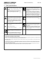
1. Safety Symbol Definitions
DANGER! − Indicates a hazardous situation which, if not
avoided, will result in death or serious injury. The possible
hazards are shown in the adjoining symbols or explained in
the text
.
DANGER ! - Indique une situation dangereuse qui, si elle
n’est pas évitée, entraînera la mort ou des blessures
graves. Les éventuels risques sont représentés par les
symboles joints ou expliqués dans le texte.
Fsafe1 2013-10
Have only trained and qualified persons install, operate,
or service this unit. Read the safety information at the
beginning of these instructions and in each section. Call
your distributor if you do not understand the directions.
For WELDING SAFETY and EMF information, read own-
er’s manual(s).
Ne confiez l’installation, l’exploitation ou l’entretien de cet
appareil qu’à des personnes compétentes et qualifiées. Lire
les directives de sécurité au début de ces instructions et
dans chaque section. Appeler votre distributeur si vous
ne comprenez pas les directives. Lire le(s) manuel(s)
d’utilisateur pour des renseignements sur la SÉCURITÉ
DE SOUDAGE et les champs électromagnétiques.
Fsafe15 2013-10
Indicates a hazardous situation which, if not avoided,
could result in death or serious injury. The possible ha-
zards are shown in the adjoining symbols or explained in
the text.
Indique une situation dangereuse qui si on l’évite pas peut
donner la mort ou des blessures graves. Les dangers
possibles sont montrés par les symboles joints ou sont
expliqués dans le texte.
Fsafe2 2013-10
Beware of moving parts.
Porter des lunettes de sécurité avec écrans latéraux.
Fsafe8 2013-10
NOTICE
Indicates statements not related to personal injury.
Indique des déclarations pas en relation avec des blessu-
res personnelles.
Indicates special instructions.
Indique des instructions spécifiques.
Fsafe3 2013-10
Tipping equipment can cause injury and damage
equipment. Do not put any body part under unit while
lifting. Use adequate blocks as needed to support unit
while doing job.
Un appareil qui bascule peut s’endommager ou causer
des blessures. Lors du levage, ne pas laisser de parties
du corps sous l’appareil. Utiliser des cales appropriées
pour soutenir l’appareil.
Engsafe5 2013-10
Beware of electric shock from wiring. Disconnect input
power before installing this kit. Reinstall all panels and
covers.
Attention aux décharges électriques au contact des
câbles. Couper l’alimentation électrique avant d’installer
ce kit. Réinstaller tous les panneaux et couvercles.
Fsafe7 2013-10
CALIFORNIA PROPOSITION 65 WARNINGS
PROPOSITION CALIFORIENNE 65 AVERTISSEMENTS
Welding or cutting equipment produces fumes or gases which contain chemicals known to the State of California to cause birth defects and,
in some cases, cancer. (California Health & Safety Code Section 25249.5 et seq.)
This product contains chemicals, including lead, known to the state of California to cause cancer, birth defects, or other reproductive harm.
Wash hands after use.
Les équipements de soudage et de coupage produisent des fumées et des gaz qui contiennent des produits chimiques dont l’État de Ca-
lifornie reconnaît qu’ils provoquent des malformations congénitales et, dans certains cas, des cancers. (Code de santé et de sécurité de
Californie, chapitre 25249.5 et suivants)
Ce produit contient des produits chimiques, notamment du plomb, dont l’État de Californie reconnaît qu’ils provoquent des cancers, des
malformations congénitales ou d’autres problèmes de procréation. Se laver les mains après utilisation.
Fsafe4 2013-10

OM-269 520 Page 2
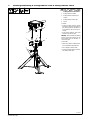
2. Installing/Uninstalling A Rolling Inductor From A Rolling Inductor Stand
267 565-B
! Turn Off induction power
source before connecting
Rolling Inductor to the stand.
1 Rolling Inductor Handles
2 Rolling Inductor Stand Top As-
sembly
3 Rolling Inductor Stand Clips
4 T-Bolt
To Install:
• Position Rolling Inductor upside
down above stand top assembly so
that Rolling Inductor handles are
in-line with the clips on the top as-
sembly.
• Push Rolling Inductor down until
handles snap into the clips.
NOTICE − When installed, the Rolling
Inductor should be centered on the
top assembly and the handles se-
cured in the clips.
To Uninstall:
• Make sure t-bolts are tightened be-
fore uninstalling Rolling Inductor.
• Place weight on feet of stand.
• Pull up on Rolling Inductor until han-
dles release from clips.
1
3
1
3
2
4

OM-269 520 Page 3
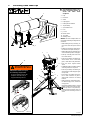
3. Positioning Stand Under Pipe
270 019-B
! Turn Off induction power source
before positioning Rolling In-
ductor and stand under
workpiece.
1 Pipe
2 Positioner
3 Stand
4 Pipe Support
5 Rolling Inductor Wheels
6 Top Assembly
7 Quick Release Pin
8 Lock
9 J-Hook
10 Bottom T-Bolt
11 Top T-Bolt
12 Warning Label
NOTICE − Be sure workpiece does not
move while positioning Rolling Inductor
and stand.
• While holding the top assembly, re-
move and retain the quick release
pin.
• Rotate top assembly to desired posi-
tion and re-insert quick release pin.
• With Rolling Inductor installed, place
stand in desired position under pipe.
• Hold top assembly and loosen bot-
tom T-bolt. Lift lock.
• Raise top assembly until Rolling In-
ductor wheels are in contact with
pipe, or until stand is fully extended.
• Push lock down. Tighten bottom
T-bolt.
• If additional height is needed, hold top
assembly and loosen top T-bolt.
• Raise top assembly until Rolling In-
ductor wheels contact the pipe. Tight-
en top T-bolt.
• If necessary, fine adjust stand posi-
tion so that center-line of joint is
aligned with center-line of Rolling
Inductor.
• After positioning, route Rolling Induc-
tor cable through J-hook, and secure
using zip-ties.
• To lower the Rolling Inductor, support
weight of head and loosen top t-bolt.
Lower top section. Keep head sup-
ported and loosen bottom t-bolt. Lift
lock and lower remaining section of
stand.
2
5
1
4
5
7
8
9
10
11
9
3
6
IMPROPER USE can injure,
and damage equipment.
Do not use stand to support the
workpiece. Use stand only to
support the Rolling Inductor.
269519-A
WARNING
12

OM-269 520 Page 4
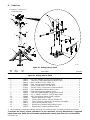
4. Parts List
270 112-B
. Hardware is common and not
available unless listed.
3
4
7
11
9
14
1
13
8
6
10
5
15
16
2
12
3
Figure 4-1. Rolling Inductor Stand
Description
Part
No.
Dia.
Mkgs.
Item
No.
Figure 4-1. Rolling Inductor Stand
Quantity
1 269173 Pin, Quick Release .375 Dia X 1.300 Usable LG 1.. .............. .. .....................
2 269165 Tube Assy, Small Welded Rolling Inductor Stand 1.. .............. .. ....................
3 269174 Bolt, T-handle 375-16 X 3.688 L Stl 2.. .............. .. ...............................
4 269169 Plate, Locking Rolling Inductor Stand 1.. .............. .. ..............................
5 271153 Spacer, Cable Mount .375 THK GFPC 1.. .............. .. .............................
6 271152 Support, Cable J−Hook Nylon 2.000in Bundle Blk 1.. .............. .. ....................
7 +269153 Assy, Welded Base Rolling Inductor Stand 1.. ............. .. ..........................
269519 Label, Warning Rolling Inductor Stand 1.................... .. .............................
8 269159 Tube Assy, Middle Welded Rolling Inductor Stand 1.. .............. .. ....................
9 269678 Clip, C .500ID X .938OD X .150THK Nylon w/tab 2.. .............. .. ....................
10 269406 Assy, Head Rolling Inductor Stand (Includes) 1.. .............. .. ........................
11 192362 Bracket, Mtg Nyl 1/2 Conduit 2.. .............. .... ....................................
12 269448 Stand−Off, No 10−32 X .250 Lg .375 Hex SST 2.. .............. .... .....................
13 269171 Foot, Push Rivet .59ODX.35H .04-.08THK .165 Mtg Blk 4.. .............. .... ............
14 269170 Spring, Rolling Inductor Stand 4.. .............. .... ...................................
15 269161 Bracket Assy, Welded Rolling Inductor Stand 1.. .............. .... ......................
16 269166 Bracket Assy, Top Rolling Inductor Stand 1.. .............. .... .........................
+ When ordering a component originally displaying a precautionary label, the label should also be ordered.
To maintain the factory original performance of your equipment, use only Manufacturer’s Suggested
Replacement Parts. Model and serial number required when ordering parts from your local distributor.
-
 1
1
-
 2
2
-
 3
3
-
 4
4


Miller PROHEAT ROLLING INDUCTOR STAND Le manuel du propriétaire
- Taper
- Le manuel du propriétaire
- Ce manuel convient également à
dans d''autres langues
Documents connexes
-
Miller PROHEAT ROLLING INDUCTOR Le manuel du propriétaire
-
-
Miller MJ010116G Le manuel du propriétaire
-
Miller MH150058G Le manuel du propriétaire
-
-
Miller PROHEAT 35 CE 907271, 907298, 907432 Le manuel du propriétaire
-
-
-
-