KOBE Brand Range Hood
Model No. / N
os
de modèles / Modelo No.
RA0230SQB
RA0236SQB
RA0242SQB
RA0248SQB
RA-02 SERIES – 18” HEIGHT
INSTALLATION INSTRUCTIONS
AND OPERATION MANUAL
MANUEL D'INSTALLATION
ET MODE D'EMPLOI
INSTRUCCIONES DE INSTALACIÓN
Y MANUAL DE OPERACIÓN

[ENGLISH] ..................................................................................................................................1
[FRENCH] .................................................................................................................................24
[SPANISH] ................................................................................................................................47

1
- READ AND SAVE THESE INSTRUCTIONS -
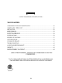
CONTENTS
IMPORTANT SAFETY INSTRUCTIONS .....................................................................................2
COMPONENTS OF PACKAGE...................................................................................................4
INSTALLATION ...........................................................................................................................5
OPERATION INSTRUCTIONS....................................................................................................9
MAINTENANCE ........................................................................................................................11
SPECIFICATIONS ....................................................................................................................13
MEASUREMENTS & DIAGRAMS .............................................................................................14
PARTS LIST ..............................................................................................................................15
CIRCUIT DIAGRAM ..................................................................................................................18
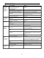
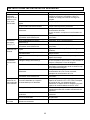
TROUBLE SHOOTING .............................................................................................................19
DISCLAIMER ............................................................................................................................20
WARRANTY .............................................................................................................................21
PRODUCT REGISTRATION .....................................................................................................23
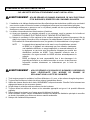
- READ ALL INSTRUCTIONS CAREFULLY BEFORE STARTING -
ALL WIRING MUST BE DONE BY A PROFESSIONAL AND IN
ACCORDANCE WITH NATIONAL AND LOCAL ELECTRICAL CODES.

2
IMPORTANT SAFETY INSTRUCTIONS
- PLEASE READ THIS SECTION CAREFULLY BEFORE INSTALLATION -
: TO REDUCE THE RISK OF FIRE, ELECTRIC SHOCK OR PERSONAL
INJURY, OBSERVE THE FOLLOWING:
1) Installation and electrical wiring must be done by qualified professionals and in accordance with all
applicable codes and standards, including fire-rated construction.
2) When cutting or drilling into wall or ceiling, be careful not to damage electrical wiring or other hidden
utilities.
3) Ducted fans must be vented to the outside.
a) Before servicing or cleaning unit, open the light panel and SWITCH POWER OFF AT SERVICE
PANEL.
b) Clean all grease laden surfaces frequently. To reduce the risk of fire and to disperse air
properly, make sure to vent air outside. DO NOT vent exhaust air into wall spaces, attics, crawl
spaces or garages.
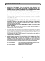
NOTE - This warranty is invalid without an authorized agent’s receipt or if unit is
damaged due to misuse, poor installation, improper use, mistreatment,
negligence or any other circumstances beyond the control of KOBE
RANGE HOODS authorized agents. Any repair carried out without the
supervision of KOBE RANGE HOODS authorized agents will
automatically void the warranty.
- KOBE RANGE HOODS will not be held responsible for any damages to
personal property or real estate or any bodily injuries whether caused
directly or indirectly by the range hood.
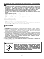
: TO REDUCE THE RISK OF PERSONAL INJURY IN THE EVENT OF A RANGE
TOP GREASE FIRE:
1. Keep all fan, baffle/spacer/filter/oil tunnel/oil container and grease-laden surfaces clean. Grease
should not be allowed to accumulate on fan, baffle/spacer/filter/oil tunnel/oil container.
2. Always turn hood ON when cooking.
3. Use high settings on cooking range ONLY when necessary.
4. Do not leave cooking range unattended when cooking.
5. Always use cookware and utensils appropriate for the type and amount of food prepared.
6. Use this unit only in the manner intended by the manufacturer.
7. Before servicing, switch power off at service panel and lock service panel (if possible) to prevent
power from switching on accidentally.
8. Clean ventilating fan frequently.

3
What to Do In The Event Of a Range Top Grease Fire
• SMOTHER FLAMES with a tight fitting lid, cookie sheet, or metal tray, and then turn off the burner.
KEEP FLAMMABLE OR COMBUSTIBLE MATERIAL AWAY FROM FLAMES. If the flames do not
go out immediately, EVACUATE THE AREA AND CALL THE FIRE DEPARTMENT or 911.
• NEVER PICK UP A BURNING PAN – You May Get Burned.
• DO NOT USE WATER, including wet dishcloths or towels – a violent steam blast will result.
• Use an extinguisher ONLY if:
a) You have a Class A, B, C extinguisher and know how to operate it.
b) The fire is small and contained in the area where it started.
c) The fire department has been called.
d) You can fight the fire with your back to an exit.
What to Do If You Smell Gas
-
Extinguish any open flame.
-
Do not try to turn on the lights or any type of appliance.
-
Open all doors and windows to disperse the gas. If you still smell gas, call the Gas Company and
Fire Department right away.
1) For general ventilation use only. Do not use to exhaust hazardous or explosive materials and
vapors.
2) To reduce the risk of fire, use only metal ductwork. Sufficient air is needed for proper combustion
and exhausting of gases through the flue (chimney) to prevent back drafting.
3) Follow the heating equipment manufacturer’s guideline and safety standards such as those
published by the National Fire Protection Association (NFPA), and the American Society for
Heating, Refrigeration and Air Conditioning Engineers (ASHRAE), and code authorities.
4) Activating any switch on may cause ignition or an explosion.
5) Due to the size and weight of this hood, two people installation is recommended.
ELECTRICAL SHOCK HAZARD – Can result in serious injury or death.
Disconnect appliance from electric power before servicing. If equipped,
the fluorescent light bulb contains small amounts of mercury, which
must be recycled or disposed of according to Local, State, and Federal
Codes.

4
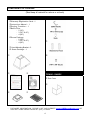
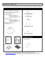
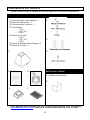
COMPONENTS OF PACKAGE
(Must keep all material for returns or refunds)
RANGE HOOD BOX
c
KOBE Range Hood – 1
d
Warranty Registration Card –1
e
Instructions Manual – 1
f
Ducting Transition – 1
g
Baffle Filter
- 2 (30”)
- 3 (36” & 42”)
- 4 (48”)
h
Screw Package
- 2 (30”)
- 3 (36” & 42”)
- 4 (48”)
i
Hood-Mounting Bracket – 2
j
Screw Package – 1
c
d e
f g
h
i
j
BOX 2 OF 2
ITEM NO.: RA02DC
k
Duct Cover
k
- FOR MORE INFORMATION, PLEASE VISIT OUR WEBSITE www.KOBERangeHoods.com OR
CONTACT KOBE RANGE HOODS AT (626) 775-8880.

5
INSTALLATION
PLEASE READ ENTIRE INSTRUCTIONS BEFORE PROCEEDING
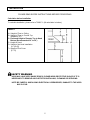
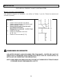
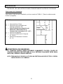
Calculation before Installation
To calculate installation, please refer to TABLE 1. (All calculation in inches.)
TABLE 1
A = Height of Floor to Ceiling
B = Height of Floor to Counter Top
(Standard: 36”)
C = Preferred Height of Counter Top to Hood
Bottom (Recommended 30” to 36”)
D = Height of Hood
E = Height of the Hood Installation
[A – (B+C)]
F = Height of Duct Cover
[E – D]
HOOD MAY HAVE VERY SHARP EDGES; PLEASE WEAR PROTECTIVE GLOVES IF IT IS
NECESSARY TO REMOVE ANY PARTS FOR INSTALLING, CLEANING OR SERVICING.
NOTE: BE CAREFUL WHEN USING ELECTRICAL SCREWDRIVER, DAMAGE TO THE HOOD
MAY OCCUR.

6
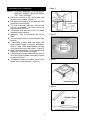
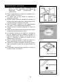
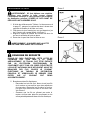
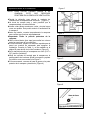
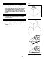
Preparation before Installation
NOTE: TO AVOID DAMAGE TO YOUR HOOD,
PREVENT DEBRIS FROM ENTERING
THE VENT OPENING.
Decide the location of the venting pipe from
the hood to the outside. (Figure 1)
A straight, short venting run will allow the hood
to perform more efficiently.
Try to avoid as many transitions, elbows, and
long run as possible. This may reduce the
performance of the hood.
Temporarily wire the hood to test for proper
operation before installing
Important: Peel any protective film off the
hood.
Use duct tape to seal the joints between pipe
sections.
If necessary, prepare back wall frame with
cross framing lumber for secure installation.
Refer to Table 1 and measurements on Page
14 to decide the level of the lumber. (Figure 2)
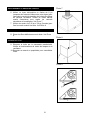
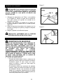
Attach ducting transition to hood exhaust with
eight (3/16” x 3/8”) screws (included).
Loosen hood-mounting brackets at the back of
the hood, adjust brackets and tighten screws
as shown in Figure 3.
If necessary, remove the rubber stand on the
back of the hood and discard. (Figure 4)
Figure 1
Figure 2
Figure 3
Figure 4

7
Hood Installation
CAUTION: If required to move the
cooking range to install the hood, turn off
the power on an electric range at the main
electrical box. SHUT OFF THE GAS
BEFORE MOVING A GAS RANGE.
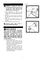
1. Using references in Table 1 and
measurements on Page 14, mark the leveling
locations point for hood-mounting bracket on
the wall.
2. Secure two mounting screws (not provided) to
the wall, leaving an 1/8” space from the wall.
(Figure 5)
3. Align the hood-mounting bracket to the
mounting screws on the wall and hang hood
into place.
4. Secure and tighten the mounting screws.
CAUTION: MAKE SURE HOOD IS
SECURE BEFORE RELEASING.
Wiring to Power Supply
RISK OF ELECTRICAL SHOCK. THIS RANGE
HOOD MUST BE PROPERLY GROUNDED.
MAKE SURE THIS IS DONE BY SPECIALIZED
ELECTRICIAN IN ACCORDANCE WITH ALL
APPLICABLE NATIONAL AND LOCAL
ELECTRICAL CODES. BEFORE CONNECTING
WIRES, SWITCH POWER OFF AT SERVICE
PANEL AND LOCK SERVICE PANEL TO
PREVENT POWER FROM BEING SWITCHED
ON ACCIDENTALLY.
5. Connect the electrical wires.
- Connect three wires (black, white and
green) to house wires and cap with wire
connectors. Connect according to color:
black to black, white to white, and green to
green as shown on Figure 6.
- If necessary to hide the electrical wire
connections, push wires back into the
wiring box. Access the wire connections
underneath the hood. Make sure wires do
not slip between motor or any moving parts
to prevent any damage.
Figure 5
Figure 6

8
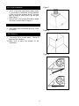
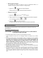
Duct Cover Installation
6. Use 8” round steel pipe (follow building codes
in your area) to connect the ducting transition
on the hood to the ductwork above. Use duct
tape to make all joints secure and air tight.
Refer Figure 7.
7. Use four 3/16” x 3/8” screws (included) to attach
duct cover to hood. Refer to Figure 8.
Install Accessories
8. Place baffle filters underneath the hood. Refer
to Figure 9.
Final Assembly
9. Turn power ON in control panel. Check all
lights and fan operation.
10. Make sure to leave this manual for the
homeowner.
Figure 7
Figure 8
Figure 9

9
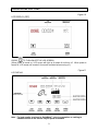
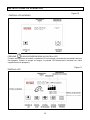
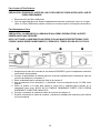
OPERATION INSTRUCTIONS
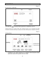
Figure 10
LCD DISPLAY (OFF)
PRESS
TO TURN ON/OFF THE LCD SCREEN
(When power is turned on, LCD screen will light up & remain lit until turn off. When power is
turned off, LCD screen will remain lit for several seconds before turning off.)
Figure 11
LCD DISPLAY
Note: For best results, turn hood to QuietMode™ prior to preparation or cooking to
establish airflow in the kitchen. Adjust speed as needed.

10
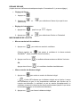
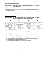
GENERAL SETUP
(During menu option, if a function is not chosen within 10 seconds, the icon will stop flashing &
menu option will end.
z
Setting Time
1. Press
until time icon flashes.
2. Press
or to select current time by hh:mm.
ƽ
Temperature Scale Setting
1. Press
until icon flashes.
2. Press
or to select Celsius or Fahrenheit.
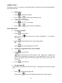
HOOD OPERATION
z
Turning Fan ON/OFF
1. Press
to turn fan ON.
(Each press of
will cycle the fan through QuietMode™, Low, Medium,
High, and off.)
2. Press
once will place fan on 3 minute delay shutoff.
OR
Press
twice will immediately turn fan OFF.
z
Turning ISC (Integrated Sensor Control) ON/OFF
1. Press
to turn ISC ON.
(
will indicate that the ISC system is ON. When gas, or higher than
normal room temperature is detected, fan will automatically turn ON. Fan will
turn to its highest speed and decrease speed until all gas and smoke are
eliminated.)
2. Press
to turn ISC OFF.
z
Turning Lights ON
(Light control is separate from ON/OFF control. Turning power off will not turn lights
off.)
1. Press
to turn halogen lights ON.
(Each press of
will cycle the light intensity through low, high, and off.)

11
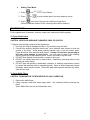
z
Setting Timer Mode
1. Press
until icon flashes.
2. Press
or to set the desire time in the timer mode by mm:ss.
3. Press
until none of the icons are flashing to begin timer.
(When countdown reaches 00:00, a warning sound will be emitted.)
MAINTENANCE
For the optimal level of operation, clean the range hood surface and baffles regularly.
To Clean Hood Surface
CAUTION: NEVER USE ABRASIVE CLEANERS, PADS, OR CLOTHS.
*** Regular care will help preserve its fine appearance.
1. Use only mild soap or detergent solutions. Dry surfaces using soft cloth.
2. If hood looks splotchy (stainless steel hood), use a stainless steel cleaner to clean the
surface of the hood. Avoid getting cleaning solution onto or into the control panel.
Follow directions of the stainless steel cleaner. Caution: Do not leave on too long as
this may cause damage to hood finish. Use soft towel to wipe off the cleaning
solution, gently rub off any stubborn spots. Use dry soft towel to dry the hood.
3. DO NOT allow deposits to accumulate or remain on the hood.
4. DO NOT use ordinary steel wool or steel brushes. Small bits of steel may adhere to the
surface and cause rusting.
5. DO NOT allow salt solutions, disinfectants, bleaches, or cleaning compounds to remain
in contact with stainless steel for extended periods. Many of these compounds contain
chemicals, which may be harmful. Rinse with water after exposure and wipe dry with a
clean lint free cloth.
To Clean Baffle Filters
CAUTION: DRAIN BAFFLE FILTERS BEFORE OIL WILL OVERFLOW.
1. Remove the baffle filters.
2. Using a sponge, wash with warm soapy water. Dry completely before returning into
place.
(Note: Baffle Filters are top rack dishwasher safe.)

12
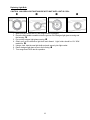
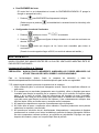
Replacing Light Bulb
CAUTION: HALOGEN LIGHT UNIT MAY BE HOT! WAIT UNTIL UNIT IS COOL.
c
cc
c
d
dd
d
e
ee
e
f
ff
f
1. Make sure all controls are off, and range hood is unplugged.
2. Place the flat-headed screwdriver into the groove of the halogen light glass covering and
the housing.
c
cc
c
3. Pop out the halogen light glass covering. d
dd
d
4. Gently pull out the defective light bulb and discard. Light bulbs should be 12V 20W
maximum.
e
ee
e
5. Using a cloth, hold the new light bulb and push securely into light socket.
6. Return halogen light glass cover to the housing.
f
ff
f
7. Turn range hood ON to test for operation.

13
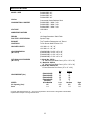
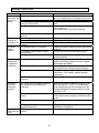
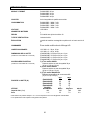
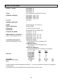
SPECIFICATIONS
MODEL / SIZE
RA0230SQB / 30”
RA0236SQB / 36"
RA0242SQB / 42”
RA0248SQB / 48”
COLO
R
Commercial Grade Stainless Steel
CONSUMPTION / AMPERE
RA0230SQB – 300W / 3.0A
RA0236SQB – 300W / 3.0A
RA0242SQB – 320W / 3.0A
RA0248SQB – 320W / 3.0A
VOLTAGE
120V 60Hz
NUMBER OF MOTORS
1
DESIGN
18-Gauge Seamless / Satin Finish
FAN TYPE: CENTRIFUGAL
Squirrel Cage
EXHAUST
Top Transition Rectangular to 8” Round
CONTROLS
Touch Screen Multi Function LCD
HALOGEN LIGHTS
12V 20W x 2 – 30”, 36”
12V 20W x 3 – 42”, 48”
HOOD DIMENSION
(W x D x H)
(RA0230SQB) 29-3/4” x 24” x 18”
(RA0236SQB) 35-3/4” x 24” x 18”
(RA0242SQB) 41-3/4” x 24” x 18”
(RA0248SQB) 47-3/4” x 24” x 18”
OPTIONAL ACCESSORIES
(W x D x H)
1) Model No. SSP30
30” Stainless Steel Back Panel (30” x 1/10” x 32”)
2) Model No. SSP36
36” Stainless Steel Back Panel (36” x 1/10” x 32”)
3) Model No. RA02DC-24
1-Piece Extension Duct Cover (15” x 12” x 24”)
HOOD WEIGHT (lbs)
Net
Gross
(R
A
0230SQB)
55 75
(R
A
0236SQB)
62 82
(R
A
0242SQB)
68 90
(R
A
0248SQB)
75 97
(RA02DC)
5 7
SPEED
QuietMode¥
¥¥
¥
Low Medium High
Air Capacity (cfm)*
400 600 800 1000
Sone
1.4* 3.5 7.0 8.0
*In House Test Static Pressure “0”. One sone is equivalent to the sound of a refrigerator at 40 decibels.
**Specifications subject to change without notice.

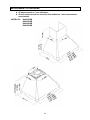
14
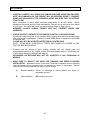
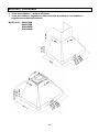
MEASUREMENTS & DIAGRAMS
All measurements in ( ) are millimeters.
All inch measurements are converted from millimeters. Inch measurements
are estimated.
MODEL NO.: R
A
0230SQB
RA0236SQB
RA0242SQB
RA0248SQB

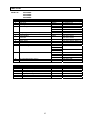
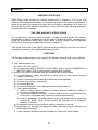
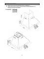
15
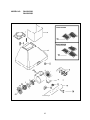
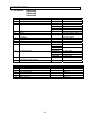
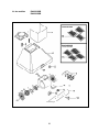
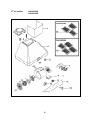
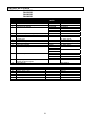
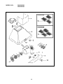
PARTS LIST
MODEL NO.: R
A
0230SQB
RA0236SQB
RA0242SQB
RA0248SQB
NO. DESCRIPTION MODEL /SIZE PART NO.
1 Ducting Transition FA-12001-0506-01 (B001-2)
2 Duct Cover RA02DC 12-56000-012-51
3 Mounting Bracket C1-0221-0092
4 Hood Casing RA0230SQB 10-5630B-51
RA0236SQB 10-5636B-51
RA0242SQB 10-5642B-51
RA0248SQB 10-5648B-51
5 Halogen Light Unit (12V 20W Max.) C1-0403-0101
6 Motor FA-12001-0302-01 (B001-4.5)
7 LCD Panel Box
LCD Panel
LCD001 FA-12001-0404-A
FA-12001-0404-B
8 Capacitor FA-12001-0401-01
9 Safety Screen FA-12001-0602-01 (B001-4.2)
10 Processor Board Box C1-0501-0102
11 Processor Board LCD001 FA-12001-0404-C
12 Transformer Light RA0230SQB C1-0402-0120-40B
RA0236SQB
RA0242SQB C1-0402-0120-60B
RA0248SQB
13 Capacitor Panel RA0230SQB C1-0201-5630
RA0236SQB C1-0201-5636
RA0242SQB C1-0201-5642
RA0248SQB C1-0201-5648
14 ISC (Integrated Sensor Control) FA-12001-0402
15 Baffle Filter B101-2590-15
BLOWER ASSEMBL
Y
NO. DESCRIPTION MODEL /SIZE PART NO.
6-1 Screws (3/16” x 1/2”) B001-4.1
6-2 Left Locknut B001-4.3
6-3 Left Squirrel Cage B001-4.4
6-4 Right Squirrel Cage B001-4.6
6-5 Right Locknut B001-4.7
6-6 Air Chamber B001-4.8

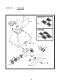
16
MODEL NO.: RA0230SQB
RA0236SQB

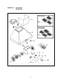
17
MODEL NO.: R
A
0242SQB
RA0248SQB

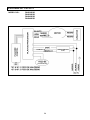
18
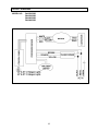
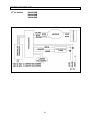
CIRCUIT DIAGRAM
MODEL NO.: R
A
0230SQB
RA0236SQB
RA0242SQB
RA0248SQB
La page est en cours de chargement...
La page est en cours de chargement...
La page est en cours de chargement...
La page est en cours de chargement...
La page est en cours de chargement...
La page est en cours de chargement...
La page est en cours de chargement...
La page est en cours de chargement...
La page est en cours de chargement...
La page est en cours de chargement...
La page est en cours de chargement...
La page est en cours de chargement...
La page est en cours de chargement...
La page est en cours de chargement...
La page est en cours de chargement...
La page est en cours de chargement...
La page est en cours de chargement...
La page est en cours de chargement...
La page est en cours de chargement...
La page est en cours de chargement...
La page est en cours de chargement...
La page est en cours de chargement...
La page est en cours de chargement...
La page est en cours de chargement...
La page est en cours de chargement...
La page est en cours de chargement...
La page est en cours de chargement...
La page est en cours de chargement...
La page est en cours de chargement...
La page est en cours de chargement...
La page est en cours de chargement...
La page est en cours de chargement...
La page est en cours de chargement...
La page est en cours de chargement...
La page est en cours de chargement...
La page est en cours de chargement...
La page est en cours de chargement...
La page est en cours de chargement...
La page est en cours de chargement...
La page est en cours de chargement...
La page est en cours de chargement...
La page est en cours de chargement...
La page est en cours de chargement...
La page est en cours de chargement...
La page est en cours de chargement...
La page est en cours de chargement...
La page est en cours de chargement...
La page est en cours de chargement...
La page est en cours de chargement...
La page est en cours de chargement...
La page est en cours de chargement...
La page est en cours de chargement...
-
 1
1
-
 2
2
-
 3
3
-
 4
4
-
 5
5
-
 6
6
-
 7
7
-
 8
8
-
 9
9
-
 10
10
-
 11
11
-
 12
12
-
 13
13
-
 14
14
-
 15
15
-
 16
16
-
 17
17
-
 18
18
-
 19
19
-
 20
20
-
 21
21
-
 22
22
-
 23
23
-
 24
24
-
 25
25
-
 26
26
-
 27
27
-
 28
28
-
 29
29
-
 30
30
-
 31
31
-
 32
32
-
 33
33
-
 34
34
-
 35
35
-
 36
36
-
 37
37
-
 38
38
-
 39
39
-
 40
40
-
 41
41
-
 42
42
-
 43
43
-
 44
44
-
 45
45
-
 46
46
-
 47
47
-
 48
48
-
 49
49
-
 50
50
-
 51
51
-
 52
52
-
 53
53
-
 54
54
-
 55
55
-
 56
56
-
 57
57
-
 58
58
-
 59
59
-
 60
60
-
 61
61
-
 62
62
-
 63
63
-
 64
64
-
 65
65
-
 66
66
-
 67
67
-
 68
68
-
 69
69
-
 70
70
-
 71
71
-
 72
72


Kobe RA0242SQB Manuel utilisateur
- Taper
- Manuel utilisateur
dans d''autres langues
- English: Kobe RA0242SQB User manual
- español: Kobe RA0242SQB Manual de usuario