Toro LX423 Lawn Tractor Manuel utilisateur
- Catégorie
- Tondeuses à gazon
- Taper
- Manuel utilisateur

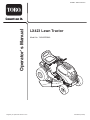
LX423 Lawn Tractor
Model No. 13AX60RG848
Register your product at www.Toro.com
769-04632 (1/13/09)
launaM s’rotarepO
Form No. 3362-179 Rev A

2
TABLE OF CONTENTS
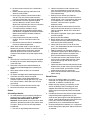
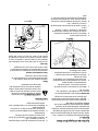
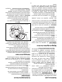
FINDING MODEL NUMBER
This Operator’s Manual is an important part of your new lawn tractor. It will help you assemble, prepare and maintain
the unit for best performance. Please read and understand what it says.
Before you start assembling your new equipment
equipment and copy the information from it in the space provided below. A sample model plate is
also illustrated below. You can locate the model plate by looking at the underside of the tractor’s seat.
This information will be necessary to use the manufacturer’s web site and/or help from a Toro Service
Dealer.
CUSTOMER SUPPORT
Please do NOT return the unit to the retailer without first contacting Customer Support.
maintenance of this unit, you can seek help from the experts. Choose from the options below:
Content Page
3
Safety Labels 7
Slope Gauge 9
Tractor Set-Up 10
Know Your Lawn Tractor 13
Operating Your Lawn Mower 16
Making Adjustments 19
Maintaining Your Lawn Tractor 20
Service 22
Off-Season Storage 26
Maintenance Chart 26
Troubleshooting 27
Specifications 28
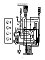
Electrical Diagram 29
Emissions Control Warranty Statement 30
Manufacturers Limited Warranty 32
Content Page
K
MODEL NUMBER SERIAL NUMBER DOM
THE TORO COMPANY
8111 LYNDALE AVE. SOUTH
BLOOMINGTON, MINNESOTA 55420-1196
TOLL FREE PHONE NUMBER: 1-888-384-9942 USA
TOLL FREE PHONE NUMBER: 1-888-848-4073 Canada
Copy the model number here:
Copy the serial number here:
6ISIT WWWTOROCOMFORMANYUSEFULSUGGESTIONS#LICKON#USTOMER#AREINTHE(OMEOWNERSSECTION
OFTHE4ORO3OLUTIONS#ENTERANDHELPISIMMEDIATELYAVAILABLE
)FYOUHAVEQUESTIONSCONCERNINGYOURTRACTORPLEASECALLUSAT53
OR#ANADA

3
SECTION 1: IMPORTANT SAFE OPERATION PRACTICES
WARNING: This symbol points out important safety instructions which, if not followed, could endanger
the personal safety and/or property of yourself and others. Read and follow all instructions in this manual
before attempting to operate this machine. Failure to comply with these instructions may result in personal
injury. When you see this symbol—heed its warning.
DANGER: This machine was built to be operated according to the rules for safe operation in this man-
ual. As with any type of power equipment, carelessness or error on the part of the operator can result in
serious injury. This machine is capable of amputating hands and feet and throwing objects. Failure to
observe the following safety instructions could result in serious injury or death.
California Proposition 65
Engine Exhaust, some of its constituents, and certain vehicle components contain or emit
chemicals known to State of California to cause cancer and birth defects or other reproductive harm.
Battery posts, terminals, and related accessories contain lead and lead compounds,
chemicals known to the State of California to cause cancer and reproductive harm. Wash hands after
handling.
General Operation
1. Read, understand, and follow all instructions on the
machine and in the manual(s) before attempting to
assemble and operate. Keep this manual in a safe
place for future and regular reference and for
ordering replacement parts.
2. Be familiar with all controls and their proper
operation. Know how to stop the machine and
disengage them quickly.
3. Never allow children under 14 years of age to oper-
ate this machine. Children 14 and over should read
and understand the instructions and safe operation
practices in this manual and on the machine and
should be trained and supervised by an adult.
4. Never allow adults to operate this machine without
proper instruction.
5. To help avoid blade contact or a thrown object
injury, keep bystanders, helpers, children and pets
at least 75 feet from the machine while it is in
operation. Stop machine if anyone enters the area.
6. Thoroughly inspect the area where the equipment
is to be used. Remove all stones, sticks, wire,
bones, toys, and other foreign objects which could
be picked up and thrown by the blade(s). Thrown
objects can cause serious personal injury.
7. Plan your mowing pattern to avoid discharge of
material toward roads, sidewalks, bystanders and
the like. Also, avoid discharging material against a
wall or obstruction which may cause discharged
material to ricochet back toward the operator.
8. Always wear safety glasses or safety goggles dur-
ing operation and while performing an adjustment
or repair to protect your eyes. Thrown objects
which ricochet can cause serious injury to the eyes.
9. Wear sturdy, rough-soled work shoes and close-
fitting slacks and shirts. Loose fitting clothes and
jewelry can be caught in movable parts. Never
operate this machine in bare feet or sandals.
10. Be aware of the mower and attachment discharge
direction and do not point it at anyone. Do not
operate the mower without the discharge cover or
entire grass catcher in its proper place.
11. Do not put hands or feet near rotating parts or
under the cutting deck. Contact with the blade(s)
can amputate hands and feet.
12. A missing or damaged discharge cover can cause
blade contact or thrown object injuries.
13. Stop the blade(s) when crossing gravel drives,
walks, or roads and while not cutting grass.
14. Watch for traffic when operating near or crossing
roadways. This machine is not intended for use on
any public roadway.
15. Do not operate the machine while under the
influence of alcohol or drugs.
16. Mow only in daylight or good artificial light.
17. Never carry passengers.
18. Disengage blade(s) before shifting into reverse.
Back up slowly. Always look down and behind
before and while backing to avoid a back-over
accident.
19. Slow down before turning. Operate the machine
smoothly. Avoid erratic operation and excessive
speed.
20. Disengage blade(s), set parking brake, stop engine
and wait until the blade(s) come to a complete stop
before removing grass catcher, emptying grass,
unclogging chute, removing any grass or debris, or
making any adjustments.

4
21. Never leave a running machine unattended.
Always turn off blade(s), place transmission in
neutral, set parking brake, stop engine and remove
key before dismounting.
22. Use extra care when loading or unloading the
machine into a trailer or truck. This machine should
not be driven up or down ramp(s), because the
machine could tip over, causing serious personal
injury. The machine must be pushed manually on
ramp(s) to load or unload properly.
23. Muffler and engine become hot and can cause a
burn. Do not touch.
24. Check overhead clearances carefully before driving
under low hanging tree branches, wires, door
openings etc., where the operator may be struck or
pulled from the machine, which could result in
serious injury.
25. Disengage all attachment clutches, depress the
brake pedal completely and shift into neutral before
attempting to start engine.
26. Your machine is designed to cut normal residential
grass of a height no more than 10”. Do not attempt
to mow through unusually tall, dry grass (e.g.,
pasture) or piles of dry leaves. Dry grass or leaves
may contact the engine exhaust and/or build up on
the mower deck presenting a potential fire hazard.
27. Use only accessories and attachments approved
for this machine by the machine manufacturer.
Read, understand and follow all instructions
provided with the approved accessory or
attachment.
28. Data indicates that operators, age 60 years and
above, are involved in a large percentage of riding
mower-related injuries. These operators should
evaluate their ability to operate the riding mower
safely enough to protect themselves and others
from serious injury.
29. If situations occur which are not covered in this
manual, use care and good judgment. Contact your
customer service representative for assistance.
Slope Operation
Slopes are a major factor related to loss of control and
tip-over accidents which can result in severe injury or
death. All slopes require extra caution. If you cannot
back up the slope or if you feel uneasy on it, do not mow
it.
For your safety, use the slope gauge included as part of
this manual to measure slopes before operating this
machine on a sloped or hilly area. If the slope is greater
than 15 degrees as shown on the slope gauge, do not
operate this machine on that area or serious injury
could result.
Do:
1. Mow up and down slopes, not across. Exercise
extreme caution when changing direction on
slopes.
2. Watch for holes, ruts, bumps, rocks, or other
hidden objects. Uneven terrain could overturn the
machine. Tall grass can hide obstacles.
3. Use slow speed. Choose a low enough speed
setting so that you will not have to stop or shift while
on the slope. Tires may lose traction on slopes
even though the brakes are functioning properly.
Always keep machine in gear when going down
slopes to take advantage of engine braking action.
4. Follow the manufacturer’s recommendations for
wheel weights or counterweights to improve
stability.
5. Use extra care with grass catchers or other
attachments. These can change the stability of the
machine.
6. Keep all movement on the slopes slow and gradual.
Do not make sudden changes in speed or direction.
Rapid engagement or braking could cause the front
of the machine to lift and rapidly flip over backwards
which could cause serious injury.
7. Avoid starting or stopping on a slope. If tires lose
traction, disengage the blade(s) and proceed
slowly straight down the slope.
Do Not:
1. Do not turn on slopes unless necessary; then, turn
slowly and gradually downhill, if possible.
2. Do not mow near drop-offs, ditches or
embankments. The mower could suddenly turn
over if a wheel is over the edge of a cliff, ditch, or if
an edge caves in.
3. Do not try to stabilize the machine by putting your
foot on the ground.
4. Do not use a grass catcher on steep slopes.
5. Do not mow on wet grass. Reduced traction could
cause sliding.
6. Do not shift to neutral and coast downhill. Over-
speeding may cause the operator to lose control of
the machine resulting in serious injury or death.
7. Do not tow heavy pull behind attachments (e.g.
loaded dump cart, lawn roller, etc.) on slopes
greater than 5 degrees. When going down hill, the
extra weight tends to push the tractor and may
cause you to loose control (e.g. tractor may speed
up, braking and steering ability are reduced,
attachment may jack-knife and cause tractor to
overturn).
Children
1. Tragic accidents can occur if the operator is not
alert to the presence of children. Children are often
attracted to the machine and the mowing activity.
They do not understand the dangers. Never
assume that children will remain where you last
saw them.
a. Keep children out of the mowing area and in
watchful care of a responsible adult other than
the operator.

5
b. Be alert and turn machine off if a child enters
the area.
c. Before and while backing, look behind and
down for small children.
d. Never carry children, even with the blade(s)
shut off. They may fall off and be seriously
injured or interfere with safe machine operation.
e. Use extreme care when approaching blind
corners, doorways, shrubs, trees or other
objects that may block your vision of a child who
may run into the path of the machine.
f. To avoid back-over accidents, always
disengage the cutting blade(s) before shifting
into Reverse. If equipped, the “Reverse Caution
Mode” should not be used when children or
others are around.
g. Keep children away from hot or running
engines. They can suffer burns from a hot
muffler.
h. Remove key when machine is unattended to
prevent unauthorized operation.
2. Never allow children under 14 years of age to
operate this machine. Children 14 and over should
read and understand the instructions and safe
operation practices in this manual and on the
machine and should be trained and supervised by
an adult.
Towing
1. Tow only with a machine that has a hitch designed
for towing. Do not attach towed equipment except
at the hitch point.
2. Follow the manufacturers recommendation for
weight limits for towed equipment and towing on
slopes.
3. Never allow children or others in or on towed
equipment.
4. On slopes, the weight of the towed equipment may
cause loss of traction and loss of control.
5. Always use extra caution when towing with a
machine capable of making tight turns (e.g. “zero-
turn” ride-on mower). Make wide turns to avoid
jack-knifing.
6. Travel slowly and allow extra distance to stop.
7. Do not shift to neutral and coast downhill.
Service
Safe Handling of Gasoline:
1. To avoid personal injury or property damage use
extreme care in handling gasoline. Gasoline is
extremely flammable and the vapors are
explosive. Serious personal injury can occur when
gasoline is spilled on yourself or your clothes which
can ignite. Wash your skin and change clothes
immediately.
a. Use only an approved gasoline container.
b. Never fill containers inside a vehicle or on a
truck or trailer bed with a plastic liner. Always
place containers on the ground away from your
vehicle before filling.
c. When practical, remove gas-powered
equipment from the truck or trailer and refuel it
on the ground. If this is not possible, then refuel
such equipment on a trailer with a portable
container, rather than from a gasoline
dispenser nozzle.
d. Keep the nozzle in contact with the rim of the
fuel tank or container opening at all times until
fueling is complete. Do not use a nozzle lock-
open device.
e. Extinguish all cigarettes, cigars, pipes and other
sources of ignition.
f. Never fuel machine indoors.
g. Never remove gas cap or add fuel while the
engine is hot or running. Allow engine to cool at
least two minutes before refueling.
h. Never over fill fuel tank. Fill tank to no more
than ½ inch below bottom of filler neck to allow
space for fuel expansion.
i. Replace gasoline cap and tighten securely.
j. If gasoline is spilled, wipe it off the engine and
equipment. Move machine to another area.
Wait 5 minutes before starting the engine.
k. To reduce fire hazards, keep machine free of
grass, leaves, or other debris build-up. Clean
up oil or fuel spillage and remove any fuel
soaked debris.
l. Never store the machine or fuel container inside
where there is an open flame, spark or pilot light
as on a water heater, space heater, furnace,
clothes dryer or other gas appliances.
m. Allow a machine to cool at least five minutes
before storing.
General Service
1. Never run an engine indoors or in a poorly
ventilated area. Engine exhaust contains carbon
monoxide, an odorless, and deadly gas.
2. Before cleaning, repairing, or inspecting, make
certain the blade(s) and all moving parts have
stopped. Disconnect the spark plug wire and
ground against the engine to prevent unintended
starting.
3. Periodically check to make sure the blades come to
complete stop within approximately (5) five
seconds after operating the blade disengagement
control. If the blades do not stop within the this time
frame, your machine should be serviced
professionally by an authorized Service Dealer.
4. Check brake operation frequently as it is subjected
to wear during normal operation. Adjust and service
as required.

6
5. Check the blade(s) and engine mounting bolts at
frequent intervals for proper tightness. Also,
visually inspect blade(s) for damage (e.g.,
excessive wear, bent, cracked). Replace the
blade(s) with the original equipment manufacturer’s
(O.E.M.) blade(s) only, listed in this manual. “Use of
parts which do not meet the original equipment
specifications may lead to improper performance
and compromise safety!”
6. Mower blades are sharp. Wrap the blade or wear
gloves, and use extra caution when servicing them.
7. Keep all nuts, bolts, and screws tight to be sure the
equipment is in safe working condition.
8. Never tamper with the safety interlock system or
other safety devices. Check their proper operation
regularly.
9. After striking a foreign object, stop the engine,
disconnect the spark plug wire(s) and ground
against the engine. Thoroughly inspect the
machine for any damage. Repair the damage
before starting and operating.
10. Never attempt to make adjustments or repairs to
the machine while the engine is running.
11. Grass catcher components and the discharge
cover are subject to wear and damage which could
expose moving parts or allow objects to be thrown.
For safety protection, frequently check components
and replace immediately with original equipment
manufacturer’s (O.E.M.) parts only, listed in this
manual. “Use of parts which do not meet the
original equipment specifications may lead to
improper performance and compromise safety!”
12. Do not change the engine governor settings or
over-speed the engine. The governor controls the
maximum safe operating speed of the engine.
13. Maintain or replace safety and instruction labels, as
necessary.
14. Observe proper disposal laws and regulations for
gas, oil, etc. to protect the environment.
15. According to the Consumer Products Safety
Commission (CPSC) and the U.S. Environmental
Protection Agency (EPA), this product has an
Average Useful Life of seven (7) years, or 270
hours of operation. At the end of the verage Useful
Life have the machine inspected annually by an
authorized service dealer to ensure that all
mechanical and safety systems are working
properly and not worn excessively. Failure to do so
can result in accidents, injuries or death.
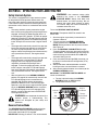
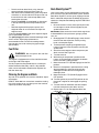
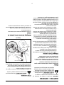
Spark Arrestor
WARNING: This machine is equipped
with an internal combustion engine and
should not be used on or near any
unimproved forest-covered, brushcovered
or grass-covered land unless the engine’s
exhaust system is equipped with a spark
arrester meeting applicable local or state
laws (if any).
If a spark arrester is used, it should be maintained in
effective working order by the operator. In the State of
California the above is required by law (Section 4442 of
the California Public Resources Code). Other states
may have similar laws. Federal laws apply on federal
lands.
A spark arrester for the muffler is available through your
nearest engine authorized service dealer .
Do not modify engine
To avoid serious injury or death, do not modify engine
in any way. Tampering with the governor setting can
lead to a runaway engine and cause it to operate at
unsafe speeds. Never tamper with factory setting of
engine governor.
Notice Regarding Emissions
Engines which are certified to comply with California
and federal EPA emission regulations for SORE (Small
Off Road Equipment) are certified to operate on regular
unleaded gasoline, and may include the following
emission control systems: Engine Modification (EM),
Oxidizing Catalyst (OC), Secondary Air Injection (SAI)
and Three Way Catalyst (TWC) if so equipped.
WARNING: YOUR RESPONSIBILITY: Restrict the use of this power machine to persons who read,
understand and follow the warnings and instructions in this manual and on the machine.

7
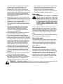
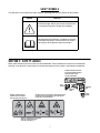
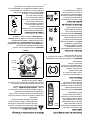
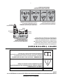
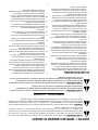
SECTION 2: SAFETY LABELS
Safety labels found on your lawn tractor are illustrated below. Always follow their instructions and heed their
warnings. If you discover a safety label is scratched, damaged or missing, order a replacement immediately.
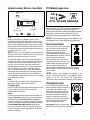
SAFETY SYMBOLS
This operator’s manual describes safety symbols and pictographs that may appear on this product.
Symbol Meaning
SAFETY ALERT SYMBOL —
Indicates Danger, Warning or Caution. May be used
in conjunction with other symbols or pictographs.
WARNING – READ OPERATOR’S MANUAL —
Read theOperator’s Manual(s) and follow all warning
and safety instructions. Failure to do so can result in
seriousinjury to the operator and/or bystanders.
WARNING! BEFORE PRESSING
BUTTON TO ENGAGE REVERSE
MOW FUNCTION, CHECK
FOR NO BYSTANDERS.
STOP
ENGINE
REVERSE
MOW
FORWARD
MOW
START
ENGINE
WARNING! THROWN OBJECTS
HAZARD: KEEP BYSTANDERS
AWAY TO AVOID FLYING OBJECTS.
WARNING! THROWN OBJECTS HAZARD:
KEEP DISCHARGE DOOR DOWN
TO AVOID FLYING OBJECTS.
WARNING! BODILY INJURY HAZARD: AVOID BODILY HARM
BY KEEPING AWAY FROM MOVING PARTS AND KEEPING
GUARDS IN PLACE AND WORKING.

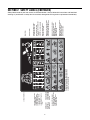
8
123 4 5
< 15 °
1. 2. 3.
WARNING! READ
OPERATOR’S
MANUAL BEFORE
USING MACHINE.
WARNING! THROWN OBJECTS HAZARD:
REMOVE OBJECTS THAT COULD
BE THROWN BY THE BLADE.
KEEP BYSTANDERS AWAY.
WARNING! BODILY INJURY HAZARD:
NEVER CARRY CHILDREN, EVEN
WHEN BLADE IS OFF.
LOOK DOWN AND BEHIND BEFORE
AND WHILE BACKING.
WARNING! LOSS OF TRACTION HAZARD:
IF MACHINE STOPS GOING UPHILL,
STOP BLADE AND BACK DOWN SLOWLY.
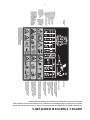
OPERATIONAL INSTRUCTIONS:
1. DISENGAGE BLADE
2. ENGAGE PARKING BRAKE
3. ADJUST THROTTLE TO FAST
4. TURN KEY / START ENGINE,
FORWARD MOW
5. CHOKE - ADJUST THROTTLE
TO FAST
PARKING BRAKE INSTRUCTIONS:
1. PRESS BRAKE PEDAL, LOCK.
ENGAGE REVERSE MOWING
1. MAKE SURE NO BYSTANDERS ARE
PRESENT
2. TURN KEY COUNTER-CLOCKWISE
DISENGAGE REVERSE MOWING
1. TURN KEY CLOCKWISE
BRAKE PEDAL
ACCELATOR PEDAL
CONSOLE FUNCTIONS
WARNING! TIPPING HAZARD:
MOW ONLY UP & DOWN SLOPES
UNDER 15 DEGREES.
DO NOT MOW SIDE TO SIDE.
AVOID SHARP TURNS.
WARNING! CUTTING HAZARD: AVOID BODILY HARM BY
KEEPING AWAY FROM MOVING PARTS AND KEEPING
GUARDS IN PLACE AND WORKING.
WARNING! REMOVE
KEY FROM IGNITION
BEFORE SERVICING
MACHINE.
SECTION 2: SAFETY LABELS (CONTINUED)
Safety labels found on your lawn tractor are illustrated below. Always follow their instructions and heed their
warnings. If you discover a safety label is scratched, damaged or missing, order a replacement immediately.

9
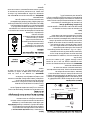
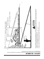
SECTION 3: SLOPE GAUGE
Use this page as a guide to determine slopes where you may not operate safely. Do not operate your lawn tractor
on such slopes.
15°
SIGHT AND HOLD THIS LEVEL WITH A VERTICAL TREE
A POWER POLE
A CORNER OF A BUILDING
OR A FENCE POST
F
O
L
D
O
N
D
O
T
T
E
D
L
I
N
E
,
R
E
P
R
E
S
E
N
T
I
N
G
A
1
5
°
S
L
O
P
E
DANGER
Do not mow on inclines with a slope in excess of 15 degrees (a rise of approximately 2-1/2 feet every 10 feet). A riding mower could
overturn and cause serious injury. If operating a walk-behind mower on such a slope, it is extremely difficult to maintain your footing
and you could slip, resulting in serious injury.
Operate RIDING mowers up and down slopes, never across the face of slopes.
Operate WALK-BEHIND mowers across the face of slopes, never up and down slopes.

10
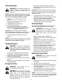
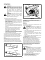
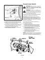
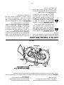
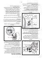
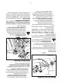
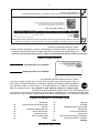
SECTION 4: TRACTOR SET-UP
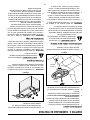
Attaching The Steering Wheel
1. If the steering wheel for your tractor did not come
attached, the hardware for attaching it has been
packed within the steering wheel, beneath steering
wheel cap. Carefully pry off the steering wheel cap
and remove the hardware.
2. With the wheels of the tractor pointing straight
forward, place the steering wheel over the steering
shaft.
3. Place the washer (with the cupped side down) over
the steering shaft and secure with the hex bolt. See
Figure 1.
Figure 1
4. Place the steering wheel cap over the center of the
steering wheel and push downward until it “clicks”
into place.
Connecting the Battery Cables
CAUTION: When attaching battery cables, always
connect the POSITIVE (Red) wire to its terminal first,
followed by the NEGATIVE (Black) wire.
For shipping reasons, both battery cables on your
equipment may have been left disconnected from the
terminals at the factory. To connect the battery cables,
proceed as follows:
NOTE: The positive battery terminal is marked Pos.
(+). The negative battery terminal is marked Neg. (–).
1. Remove the plastic cover, if present, from the
positive battery terminal and attach the red cable to
the positive battery terminal (+) with the bolt and
hex nut. See Figure 2.
2. Remove the plastic cover, if present, from the
negative battery terminal and attach the black cable
to the negative battery terminal (–) with the bolt and
hex nut. See Figure 2.
3. Position the red rubber boot over the positive
battery terminal to help protect it from corrosion.
Figure 2
NOTE: If the battery is put into service after the date
shown on top/side of battery, charge the battery as
instructed on page 23 of this manual prior to operating
the tractor.
Tire Pressure
WARNING: Never exceed the maximum
inflation pressure shown on the sidewall of the
tire.
The tires on your unit may be over-inflated for shipping
purposes. Reduce the tire pressure before operating
the tractor. Recommended operating tire pressure is
approximately 10 p.s.i. for the rear tires and 14 p.s.i. for
the front tires. Check sidewall of tire for maximum p.s.i.
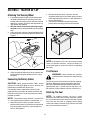
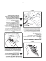
Attaching The Seat
NOTE: For shipping reasons, the seat is either
fastened to the tractor seat’s pivot bracket with a plastic
tie, or mounted backward to the pivot bracket. In either
case, free the seat from its shipping position being
careful not to bend or kink the wiring harness and follow
the instructions below to attach it.
Cap
Washer
Hex Bolt
Steering Shaft

11
1. Remove the two hex screws and nuts from the seat
pivot bracket.
2. Align the front holes of the seat mounting bracket
with the holes in the seat pivot bracket on your
tractor and secure with previously removed hex
screws and nuts. See Figure 3.
3. To adjust the position of the seat loosen the knob
on the bottom of the seat. See Figure 3. Slide the
seat forward or backward as desired. Retighten the
knob.
Figure 3
Attaching the PTO Lever
NOTE: Your tractor’s PTO lever may have already
been attached at the factory.
Tools Required
(1) 1/2" socket wrench
1. Position the PTO lever on the PTO shaft and
secure with the hex lock nut. See .
Figure 4
2. Place the PTO lever cap over the hex nut and push
downward until it “clicks” into place.
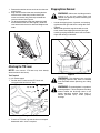
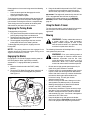
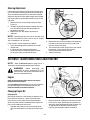
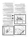
Shipping Brace Removal
WARNING: Make sure the riding mower’s
engine is off, set the parking brake and
remove the ignition key before removing the
shipping brace
.
• Locate the shipping brace, if present, and warning
tag found on the right side of the cutting deck. See
Figure 5.
• While holding the discharge chute with your left
hand, remove the shipping brace with your right
hand by grasping it between your thumb and index
finger and rotating it clockwise.
Figure 5
WARNING: The shipping brace, used for
packaging purposes only, must be removed
and discarded before operating your riding
mower.
WARNING: The mowing deck is capable of
throwing objects. Failure to operate the riding
mower without the discharge cover in the
proper operating position could result in
serious personal injury and/or property
damage.
PTO Lever
Hex Nut
Cap
PTO
Shaft

12
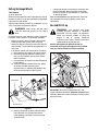
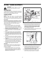
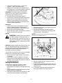
Setting the Gauge Wheels
Tools Required
(2) 9/16" wrenches
Select the height position of the cutting deck by placing
the deck lift lever in any of the six different cutting height
notches on the right fender.
Adjust the deck wheels so that they are between ¼-inch
and ½-inch above the ground as follows.
WARNING: Keep hands and feet away
from the discharge opening of the cutting
deck.
Place the tractor on a firm and level surface, preferably
pavement, refer to Figure 6, and proceed as follows:
• Place the tractor’s deck lift handle in the normally
mowing height setting, then check the gauge
wheels for contact or excessive clearance with the
surface below. There should be approximately 1/2"
clearance.
• If the wheels contact the surface adjust as follows:
a. Raise the deck lift handle to its highest setting.
b. Remove the gauge wheels by removing the
lock nuts and shoulder screws which secure
them to the deck.
c. Place the deck lift handle in the desired mowing
height setting.
d. Insert the shoulder screw with the rear gauge
wheel into the index hole that leaves
approximately 1/2" between the bottom of the
wheel and the pavement. See Figure 6.
Figure 6
e. Note the position of the index hole used; then
install the other rear gauge wheel into the
corresponding index hole of the other gauge
wheel brackets.
• If the gauge wheels have excessive clearance with
the surface below, lower the wheels to the index
hole that provides the approximate 1/2" clearance
as described above.
Refer to Leveling the Deck on page 20 of this manual for
more detailed instructions regarding various deck
adjustments.
Gas and Oil Fill-up
WARNING: Use extreme care when
handling gasoline. Gasoline is extremely
flammable and the vapors are explosive.
Never fuel machine indoors or while the
engine is hot or running. Extinguish
cigarettes, cigars, pipes, and other sources of
ignition before filling the fuel tank.
Service the engine with gasoline and oil as
instructed in the separate engine manual packed
with your tractor. Read instructions carefully.
Figure 7
IMPORTANT: You tractor is shipped with oil in the
engine. However, you MUST check the oil level before
operating. Refer to the separate engine manual packed
with your tractor.
Lock Nut
Shoulder Screw
Gauge Wheel
Fuel Tank

13
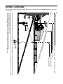
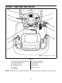
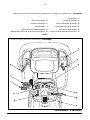
SECTION 5: KNOW YOUR LAWN TRACTOR
Figure 8
NOTE: Any reference in this manual to the RIGHT or LEFT side of the tractor is observed from operator’s position.
A Systems Indicator Monitor/Hour Meter G Throttle / Choke Control
B PTO (Blade Engage) Lever H Ignition Switch Module
C Parking Brake Lever I Brake Pedal
D Cruise Control Lever J Drive Pedal
E Shift Lever K Deck Lift Lever
F Cup Holder
S
LO
W
A
G
K
J
I
NOTE: Steering Wheel not shown for clarity.
D
B
C
H
F
E

14
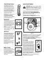
Throttle/Choke Control
The throttle/choke control is
located on the right side of the
tractor’s dash panel. This lever
controls the speed of the engine
and, when pushed all the way
forward, closes the choke for cold
starting. When set in a given
position, the throttle will maintain
a uniform engine speed.
IMPORTANT: When operating the
tractor with the cutting deck
engaged, be certain that the
throttle/choke control is always in
the FAST (rabbit) position.
Brake Pedal
The brake pedal is located on the
right front side of the tractor
above the drive pedal along the
running board. The brake pedal
can be used for sudden stops or
setting the parking brake.
NOTE: The brake pedal must
be fully pressed to activate the
safety interlock switch when
starting the tractor
.
Shift Lever
The shift lever is located on the
left side of the fender and has
three positions, FORWARD,
NEUTRAL and REVERSE. The
brake pedal must be depressed
and the tractor must not be in
motion when the moving shift
lever. See Figure 8.
IMPORTANT: Never force the shift
lever. Doing so may result in
serious damage to the tractor’s
transmission.
Deck Lift Lever
Found on your tractor’s right
fender, the deck lift lever is used
to change the height of the
cutting deck. To use, move the
lever to the left, then place in the
notch best suited for your
application.
Ignition Switch Module
WARNING: Never leave a running machine
unattended. Always disengage the PTO,
move the shift lever into Neutral, set the
parking brake, stop the engine and remove
the key to prevent unintended starting.
To start the engine, insert the key into the ignition
switch and turn clockwise to the START position.
Release the key into the NORMAL MOWING MODE
position once the engine has fired.
To stop the engine, turn the ignition key
counterclockwise to the STOP position. SeeFigure 9 .
Figure 9
IMPORTANT: Prior to operating the tractor, refer to Safety
Interlock System on page 16 and Reverse Caution Mode on
page 16 of this manual for detailed instructions
regarding the Ignition Switch Module and operating the
tractor in REVERSE CAUTION MODE.
Drive Pedal
The drive pedal is located on the
right side of the tractor, along the
running board. Press the upper
portion of the drive pedal forward to
cause the tractor to travel forward.
Press the lower portion of the drive
pedal with the ball of your right foot
(NOT your heel) to cause the tractor
to travel in reverse. Ground speed is
also controlled with the drive pedal.
The further forward or rearward that
the pedal is pivoted, the faster the
tractor will travel. The pedal will
return to its original position when it’s not pressed.
IMPORTANT: Always set the parking brake when
leaving the tractor unattended.
CI00171
N
F
R
Start
Position
Stop
Position
Normal
Mowing
Mode

15
Systems Indicator Monitor / Hour Meter
LCD
When the ignition key is rotated out of the STOP
position but not into the START position, the systems
indicator monitor displays the battery’s output, in volts,
on its LCD for approximately five seconds, after which it
displays the hours of tractor operation. Once the tractor
is started, the monitor continually displays the hours of
tractor operation on its LCD.
NOTE: Hours of tractor operation are recorded any
time the ignition key is rotated out of the STOP position,
regardless of whether the engine is started.
The Indicator Monitor will also remind the operator of
maintenance intervals for changing the engine oil. The
LCD will alternately flash the recorded hours, “CHG”
and “OIL” for five minutes, after every 50 hours of
recorded operation elapse. The maintenance interval
lasts for two hours (from 50-52, 100-102, 150-152,
etc.). The LCD will also flash as described above for
five minutes every time the tractor’s engine has been
started during this maintenance interval. Before the
interval expires, change the crankcase oil as instructed
on page 26 of this manual.
Brake
If the Brake light illuminates when attempting to start
the tractor’s engine, press the brake pedal.
PTO (Blade Engage)
If the PTO light illuminates when attempting to start the
tractor’s engine, move the PTO lever into the
disengaged (OFF) position.
Battery
It is normal for the Battery light to illuminate while the
engine is cranking during start-up, but if it illuminate’s
during operation, while the engine is running, the
battery is in need of a charge or the engine’s charging
system is not generating sufficient amperage. Refer to
the MAINTAINING YOUR LAWN TRACTOR section of this
manual for the proper battery charging procedure or
have the charging system checked by an authorized
Toro service dealer.
PTO (Blade Engage) Lever
The PTO (Blade Engage) lever is located on the left
side of the dash, next to the steering wheel. Move the
PTO (Blade Engage) lever forward to engage the
power to the cutting deck or other (separately available)
attachments; move the PTO (Blade Engage) lever
rearward to disengage the power to the attachments.
NOTE: The PTO (Blade Engage) lever must be in the
disengaged (OFF) position when starting the engine.
Cruise Control Lever
The cruise control lever is located on
the tractor dash panel, below the
steering wheel. Push the cruise
control lever downward while
traveling forward at a desired speed.
While holding the lever down, release
pressure from the drive pedal.
This will engage the cruise control
and allow the tractor to remain at that
speed without applying pressure to
the drive pedal. Press the brake
pedal or the drive pedal to deactivate cruise control.
Refer to page 17 for detailed instructions regarding
cruise control.
NOTE: Cruise control cannot be engaged at the
tractor’s fastest ground speed. If the operator should
attempt to do so, the tractor will automatically
decelerate to the fastest optimal mowing ground speed.
Parking Brake Lever
To set the parking brake, fully press
the brake pedal and push the parking
brake lever down. Hold the lever
down while taking your foot off the
brake pedal. Both the parking lever
and the brake pedal will then stay
pressed. To release the parking
brake, press the brake pedal slightly.
The parking brake lever will then
return to its original position.
IMPORTANT: Always set the parking
brake when leaving the tractor unattended.
Battery
LCD
PTO
(Blade Engage)
Parking Brake
42.0
PTO / BLADE ENGAGE
ON
OFF
PTO
P

16
SECTION 6: OPERATING YOUR LAWN TRACTOR
Safety Interlock System
This tractor is equipped with a safety interlock system
for the protection of the operator. Before each use,
check the safety interlock system for proper operation.
If the interlock system should ever malfunction, do not
operate the tractor. Contact an authorized Toro service
dealer.
• The safety interlock system prevents the engine
from cranking or starting unless the parking brake is
engaged, and the PTO (Blade Engage) lever is in
the disengaged (OFF) position. To check for proper
operation, move the PTO (Blade Engage) lever into
the engaged (ON) position and release the parking
brake. Attempts to start the tractor’s engine should
fail.
• The engine will automatically shut off if the operator
leaves the seat before engaging the parking brake.
To check for proper operation, start the tractor’s
engine, release the parking brake and momentarily
raise yourself from the seat. The engine should
stall.
• The engine will automatically shut off if the operator
leaves the tractor’s seat with the PTO (Blade
Engage) lever in the engaged (ON) position,
regardless of whether the parking brake is
engaged. To check for proper operation, start the
tractor’s engine, move the PTO (Blade Engage)
lever in the engaged (ON) position and momentarily
raise yourself from the seat. The engine should
stall.
• With the ignition key in the NORMAL MOWING
position, the engine will automatically shut off if the
PTO (Blade Engage) lever is moved into the
engaged (ON) position with the drive pedal in
position for Reverse travel. To check for proper
operation, start the tractor’s engine with the ignition
key in the NORMAL MOWING position, move the
PTO (Blade Engage) lever in the engaged (ON)
position, and place the shift lever into REVERSE.
The engine should stall.
WARNING: Do not operate the tractor if the
interlock system is malfunctioning. This
system was designed for your safety and
protection.
Reverse Caution Mode
The REVERSE CAUTION MODE position of the key
switch module allows the tractor to be operated in
reverse with the blades (PTO) engaged.
IMPORTANT: Mowing in reverse is not recommended.
WARNING: Use extreme caution while
operating the tractor in the REVERSE
CAUTION MODE. Always look down and
behind before and while backing. Do not
operate the tractor when children or others
are around. Stop the tractor immediately if
someone enters the area.
To use the REVERSE CAUTION MODE:
IMPORTANT:The operator MUST be seated in the
tractor seat.
1. Start the engine as previously instructed in this
Operator’s Manual.
2. Turn the key from the NORMAL MOWING
(Green) position to the REVERSE CAUTION
MODE (White) position of the key switch module.
See Figure 10.
3. Press the REVERSE PUSH BUTTON (Orange,
Triangular Button) at the top, right corner of the key
switch module. The red indicator light at the top, left
corner of the key switch module will be ON while
activated. See Figure 10.
4. Once activated (indicator light ON), the tractor can
be driven in reverse with the cutting blades (PTO)
engaged.
5. Always look down and behind before and while
backing to make sure no children are around.
6. After resuming forward motion, return the key to the
NORMAL MOWING position.
IMPORTANT: The REVERSE CAUTION MODE will
remain activated until:
a. The key is placed in either the NORMAL
MOWING position or STOP position.
b. The operator leaves the seat.
Figure 10
Start
Position
Stop
Position
R
everse
Push Button
Reverse
Caution Mode
Position
Indicator
Light

17
Starting the Engine
WARNING: Do not operate the tractor if the
interlock system is malfunctioning. This
system was designed for your safety and
protection.
NOTE: Service the engine with gasoline and oil as
instructed in the separate engine manual packed
with your tractor. Read instructions carefully.
1. Insert the tractor key into the ignition switch
module.
2. Place the PTO (Blade Engage) lever in the
disengaged (OFF) position.
3. Engage the tractor’s parking brake.
4. Activate the choke control.
5. Turn the ignition key clockwise to the START
position. After the engine starts, release the key. It
will return to the NORMAL MOWING position.
IMPORTANT: Do NOT hold the key in the START
position for longer than ten seconds at a time. Doing so
may cause damage to your engine’s electric starter.
6. After the engine starts, deactivate the choke
control.
NOTE: Do NOT leave the choke control on while
operating the tractor. Doing so will result in a "rich" fuel
mixture and cause the engine to run poorly.
Stopping the Engine
WARNING: If you strike a foreign object,
stop the engine and remove the ignition key.
Thoroughly inspect the machine for any
damage. Repair the damage before restarting
and operating.
1. If the blades are engaged, place the PTO/Blade
Engage lever in the disengaged (OFF) position.
2. Position the throttle control between half-throttle
and the FAST (rabbit) position.
3. Turn the ignition key counterclockwise to the STOP
position.
4. Remove the key from the ignition switch to prevent
unintended starting.
Driving The Tractor
WARNING: Avoid sudden starts, ex-
cessive speed and sudden stops.
WARNING: Do not leave the seat of the
tractor without first placing the PTO/Blade
Engage lever in the disengaged (OFF)
position, pressing the brake pedal and
engaging the parking brake. If leaving the
tractor unattended, also turn the ignition key
off and remove the key.
• Briefly depress the brake pedal to release the
parking brake. Move the throttle lever into the FAST
(rabbit) position.
IMPORTANT: Do NOT use the shift lever to change the
direction of travel when the tractor is in motion. Always
use the brake pedal to bring the tractor to a complete
stop before shifting.
• To move forward, place the shift lever in the
FORWARD position, then slowly depress the drive
pedal until the desired speed is achieved.
• To move in reverse, place the shift lever in the
REVERSE position, check that the area behind is
clear then slowly depress the drive pedal.
Driving On Slopes
Refer to the SLOPE GAUGE on page 9 to help determine
slopes where you may operate the tractor safely.
WARNING: Do not mow on inclines with a
slope in excess of 15 degrees (a rise of
approximately 2-1/2 feet every 10 feet). The
tractor could overturn and cause serious
injury.
• Mow up and down slopes, NEVER across.
• Exercise extreme caution when changing direction
on slopes.
• Watch for holes, ruts, bumps, rocks, or other
hidden objects. Uneven terrain could overturn the
machine. Tall grass can hide obstacles.
• Avoid turns when driving on a slope. If a turn must
be made, turn down the slope. Turning up a slope
greatly increases the chance of a roll over.
• Avoid stopping when driving up a slope. If it is
necessary to stop while driving up a slope, start up
smoothly and carefully to reduce the possibility of
flipping the tractor over backward.
Setting The Cruise Control
WARNING: Never engage cruise control
while traveling in Reverse.
1. Slowly press the drive pedal until the desired speed
is achieved.
2. Lightly press the cruise control lever.
3. While continuing to hold the cruise lever down, lift
your foot from the drive pedal (you should feel the
cruise latch engage).
4. Once engaged, the cruise control lever and the
drive pedal will lock in the “down” position, and the
tractor will maintain the same forward speed.
NOTE: Cruise control can not be set at the tractor’s
fastest ground speed. If the operator should attempt to
do so, the tractor will automatically decelerate to the
fastest optimal mowing ground speed.

18
Disengage the cruise control using one of the following
methods:
• Press the brake pedal to disengage the cruise
control and stop the tractor.
• Lightly press the drive pedal.
To change to the reverse direction when operating with
cruise control, press the brake pedal to disengage the
cruise control and bring the tractor to a complete stop.
Then slowly press the rear portion of the drive pedal
with the ball of your foot to travel in reverse.
Engaging the Parking Brake
To engage the parking brake:
1. Fully press the brake pedal and hold it while gently
pushing the parking brake lever downward.
2. Hold the parking brake lever down while removing
your foot from the brake pedal.
3. Once engaged, the parking brake lever and the
brake pedal will lock in the “down” position.
To disengage the parking brake, slightly press the
brake pedal.
NOTE: The parking brake must be engaged if the
operator leaves the seat with the engine running or the
engine will automatically shut off.
Engaging the Blades
Engaging the PTO (Blade Engage) transfers power to
the cutting deck or other (separately available)
attachments. To engage the blades, proceed as
follows:
1. Move the throttle control to the FAST (rabbit)
position.
2. Grasp the PTO (Blade Engage) lever and pivot it all
the way forward into the engaged (ON) position.
See Figure 11.
Figure 11
3. Keep the throttle/choke control in the FAST (rabbit)
position for the most efficient use of the cutting
deck or other (separately available) attachments
IMPORTANT: The engine will automatically shut off if the
PTO is engaged with the shift lever in position for
reverse travel and the ignition key in the NORMAL
MOWING position. Refer to Safety Interlock System on
page 16.
Using the Deck Lift Lever
To raise the cutting deck, move the deck lift lever to the
left, then place it in the notch best suited for your
application.
Mowing
WARNING: To help avoid blade contact or
a thrown object injury, keep bystanders,
helpers, children and pets at least 75 feet
from the machine while it is in operation. Stop
machine if anyone enters the area.
The following information will be helpful when using the
cutting deck with your tractor.
WARNING: Plan your mowing pattern to
avoid discharge of materials toward roads,
sidewalks, bystanders and the like. Also,
avoid discharging material against a wall or
obstruction which may cause discharged
material to ricochet back toward the operator.
• Do not mow at high ground speed, especially if a
mulch kit or grass collector is installed.
• For best results it is recommended that the first two
laps be cut with the discharge thrown towards the
center. After the first two laps, reverse the direction
to throw the discharge to the outside for the
balance of cutting. This will give a better
appearance to the lawn.
• Do not cut the grass too short. Short grass invites
weed growth and yellows quickly in dry weather.
• Mowing should always be done with the throttle
control in the FAST (rabbit) position.
• Under heavy conditions it may be necessary to go
over the cut area a second time to get a clean cut.
• Do NOT attempt to mow heavy brush and weeds
and extremely tall grass. Your tractor is designed to
mow lawns, NOT clear brush.
• Keep the blades sharp and replace the blades
when worn. Refer to Cutting Blades on page 23 of this
manual for proper blade sharpening instructions.
Engaged
Disengaged
PTO
Lever
NOTE: Steering wheel not shown for clarity.

19
SECTION 7: MAKING ADJUSTMENTS
WARNING: Never attempt to make any
adjustments while the engine is running,
Seat Adjustment
To adjust the position of the seat loosen the knob on the
bottom of the seat. See Figure 3. Slide the seat forward
or backward as desired. Retighten the knob.
Leveling the Deck
NOTE: Check the tractor’s tire pressure before
performing any deck leveling adjustments. Refer to
Tires on page 22 for information regarding tire pressure.
Front To Rear
The front of the cutting deck is supported by a stabilizer
bar that can adjusted to level the deck from front to rear.
The front of the deck should be between 1/4-inch and
3/8-inch lower than the rear of the deck. Adjust if
necessary as follows:
1. With the tractor parked on a firm, level surface,
place the deck lift lever in the top notch (highest
position) and rotate the blade nearest the discharge
chute so that it is parallel with the tractor.
2. Measure the distance from the front of the blade tip
to the ground and the rear of the blade tip to the
ground.
3. The first measurement taken should be between
1/4" and 3/8" less than the second measurement.
4. Determine the approximate distance necessary for
proper adjustment and proceed, if necessary, to the
next step.
5. From the front of the tractor, loosen the outermost
hex lock nut on the end of the deck hanger rod. See
Figure 12.
6. Tighten the inner hex nut against the front hanger
bracket to raise the front of the deck; loosen the hex
nut to lower the front of the deck. See Figure 12.
7. Retighten the outer lock nut against the inner hex
nut when proper adjustment is achieved.
Side to Side
If the cutting deck appears to be mowing unevenly, a
side to side adjustment can be performed. Adjust if
necessary as follows:
1. With the tractor parked on a firm, level surface,
place the deck lift lever in the top notch (highest
position) and rotate both blades so that they are
perpendicular with the tractor.
Figure 12
2. Measure the distance from the outside of the left
blade tip to the ground and the distance from the
outside of the right blade tip to the ground. Both
measurements taken should be equal. If they’re
not, proceed to the next step.
3. Loosen, but do NOT remove, the hex bolt on the left
deck hanger bracket. See Figure 13.
Figure 13
4. Balance the deck by using a wrench to turn the
adjustment gear (See Figure 13) up or down.
5. The deck is properly balanced when both blade tip
measurements taken earlier are equal.
6. Retighten the hex bolt on the left deck hanger
bracket when proper adjustment is achieved.
!DJUSTMENT'EAR
(EX"OLT

20
Steering Adjustment
If the tractor turns tighter in one direction than the other,
or if the ball joints are being replaced due to damage or
wear, the steering drag links may need to be adjusted.
Adjust the drag links so that equal lengths are threaded
into the ball joint on the left side and the ball joint on the
right side:
1. Remove the hex nut on the top of ball joint. See
Figure 14
2. Thread the ball joint clockwise to shorten the drag
link. Thread the ball joint counterclockwise to
lengthen the drag link.
3. Replace hex nut after proper adjustment is
achieved.
NOTE: Threading the ball joints too far onto the drag
links will cause the front tires to "toe-in" too far. Proper
toe-in is between 1/16" and 5/16".
Front tire toe-in can be measured as follows:
1. Place the steering wheel in position for straight
ahead travel
2. In front of the axle, measure the distance
horizontally from the inside of the left rim to the
inside of the right rim. Note the distance.
Figure 14
3. Behind the axle, measure the distance horizontally
from the inside of the left rim to the inside of the
right rim. Note the distance.
4. The measurement taken in front of the axle should
be between 1/16" and 5/16" less than the
measurement taken behind the axle.
5. Adjust if necessary.
SECTION 8: MAINTAINING YOUR LAWN TRACTOR
NOTE: Refer to Maintenance Chart on page 26 for a
reference of recommended maintenance intervals.
WARNING: Before performing any
maintenance or repairs, disengage PTO, set
parking brake, stop engine and remove key to
prevent unintended starting.
Engine
Refer to the separate engine manual for engine
maintenance instructions.
Check engine oil level before each use as instructed in
the separate engine manual packed with your unit.
Read and follow instructions carefully.
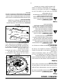
Changing Engine Oil
Draining the Oil
Running the engine for a few minutes to allow the oil in
the crankcase to warm up. Warm oil will flow more
freely and carry away more of the enigne sediment
which may have settled at the bottom of the crankcase.
Use care to avoid burns from hot oil.
• Pop open the protective cap on the end of the oil
drain valve to expose the oil drain port. See Figure
15 .
Figure 15
• Remove the oil fill cap/dipstick from the oil fill tube.
• Push oil drain hose (packed with unit) onto the oil
drain port. Route the opposite end of the hose into
an appropriate oil collection container with a
capacity great enough to collect the used oil.
Hex Nut
Ball
Joint
Drag Link
Oil Drain
Hose
Drain Port
Oil Fill
La page est en cours de chargement...
La page est en cours de chargement...
La page est en cours de chargement...
La page est en cours de chargement...
La page est en cours de chargement...
La page est en cours de chargement...
La page est en cours de chargement...
La page est en cours de chargement...
La page est en cours de chargement...
La page est en cours de chargement...
La page est en cours de chargement...
La page est en cours de chargement...
La page est en cours de chargement...
La page est en cours de chargement...
La page est en cours de chargement...
La page est en cours de chargement...
La page est en cours de chargement...
La page est en cours de chargement...
La page est en cours de chargement...
La page est en cours de chargement...
La page est en cours de chargement...
La page est en cours de chargement...
La page est en cours de chargement...
La page est en cours de chargement...
La page est en cours de chargement...
La page est en cours de chargement...
La page est en cours de chargement...
La page est en cours de chargement...
La page est en cours de chargement...
La page est en cours de chargement...
La page est en cours de chargement...
La page est en cours de chargement...
La page est en cours de chargement...
La page est en cours de chargement...
La page est en cours de chargement...
La page est en cours de chargement...
La page est en cours de chargement...
La page est en cours de chargement...
La page est en cours de chargement...
La page est en cours de chargement...
La page est en cours de chargement...
La page est en cours de chargement...
La page est en cours de chargement...
La page est en cours de chargement...
-
 1
1
-
 2
2
-
 3
3
-
 4
4
-
 5
5
-
 6
6
-
 7
7
-
 8
8
-
 9
9
-
 10
10
-
 11
11
-
 12
12
-
 13
13
-
 14
14
-
 15
15
-
 16
16
-
 17
17
-
 18
18
-
 19
19
-
 20
20
-
 21
21
-
 22
22
-
 23
23
-
 24
24
-
 25
25
-
 26
26
-
 27
27
-
 28
28
-
 29
29
-
 30
30
-
 31
31
-
 32
32
-
 33
33
-
 34
34
-
 35
35
-
 36
36
-
 37
37
-
 38
38
-
 39
39
-
 40
40
-
 41
41
-
 42
42
-
 43
43
-
 44
44
-
 45
45
-
 46
46
-
 47
47
-
 48
48
-
 49
49
-
 50
50
-
 51
51
-
 52
52
-
 53
53
-
 54
54
-
 55
55
-
 56
56
-
 57
57
-
 58
58
-
 59
59
-
 60
60
-
 61
61
-
 62
62
-
 63
63
-
 64
64


Toro LX423 Lawn Tractor Manuel utilisateur
- Catégorie
- Tondeuses à gazon
- Taper
- Manuel utilisateur
dans d''autres langues
- English: Toro LX423 Lawn Tractor User manual