Best IS170 Manuel utilisateur
- Catégorie
- Hottes
- Taper
- Manuel utilisateur
Ce manuel convient également à

BEST BY BROAN P.O. Box 140 Hartford, WI 53027
ENGLISH......................................3
FRANÇAIS..................................15
ESPAÑOL...................................27
Model IS170


- 3 -
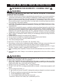
READ AND SAVE THESE INSTRUCTIONS
WARNING
TO REDUCE THE RISK OF FIRE, ELECTRIC SHOCK, OR INJURY TO PERSONS,
OBSERVE THE FOLLOWING:
1. Use this unit only in the manner intended by the manufacturer. If you have questions,
contact the manufacturer at the address or telephone number listed in the warranty.
2. Before servicing or cleaning unit, switch power off at service panel and lock service
panel to prevent power from being switched on accidentally. When the service
disconnecting means cannot be locked, securely fasten a prominent warning device,
such as a tag, to the service panel.
3. Installation work and electrical wiring must be done by a qualified person(s) in accor-
dance with all applicable codes and standards, including fire-rated construction codes
and standards.
4. Sufficient air is needed for proper combustion and exhausting of gases through the flue
(chimney) of fuel burning equipment to prevent backdrafting. Follow the heating equip-
ment manufacturer’s guidelines and safety standards such as those published by the
National Fire Protection Association (NFPA), and the American Society for Heating,
Refrigeration and Air Conditioning Engineers (ASHRAE), and the local code authorities.
5. When cutting or drilling into wall or ceiling, do not damage electrical wiring and other
hidden utilities.
6. Ducted fans must always be vented to the outdoors.
7. Do not use this unit with any separate solid-state speed control device.
8. To reduce the risk of fire, use only metal ductwork.
9. This unit must be grounded.
TO REDUCE THE RISK OF A RANGE TOP GREASE FIRE:
A. Never leave surface units unattended at high settings. Boilovers cause smoking and
greasy spillovers that may ignite. Heat oils slowly on low or medium settings.
B. Always turn hood ON when cooking at high heat or when flambeing food (i.e. Crepes
Suzette, Cherries Jubilee, Peppercorn Beef Flambe’).
C. Clean ventilating fans frequently. Grease should not be allowed to accumulate on fan or
filter.
D. Use proper pan size. Always use cookware appropriate for the size of the surface
element.
WARNING
TO REDUCE THE RISK OF INJURY TO PERSONS IN THE EVENT OF A RANGE TOP
GREASE FIRE, OBSERVE THE FOLLOWING:*
1. SMOTHER FLAMES with a close-fitting lid, cookie sheet, or metal tray, then turn off the
burner. BE CAREFUL TO PREVENT BURNS. If the flames do not go out immediately,
EVACUATE AND CALL THE FIRE DEPARTMENT.
2. NEVER PICK UP A FLAMING PAN - You may be burned.
3. DO NOT USE WATER, including wet dishcloths or towels - violent steam explosion will
result.
4. Use an extinguisher ONLY if:
A. You know you have a Class ABC extinguisher and you already know how to operate
it.
B. The fire is small and contained in the area where it started.
C. The fire department is being called.
D. You can fight the fire with your back to an exit.
* Based on “Kitchen Fire Safety Tips” published by NFPA.
!
INTENDED FOR DOMESTIC COOKING ONLY
!

- 4 -
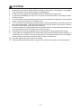
!
CAUTION
1. To reduce risk of fire and to properly exhaust air, be sure to duct air outside. Do not vent
exhaust air into spaces within walls or ceilings or into attics, crawl spaces, or garages.
2. Take care when using cleaning agents or detergents.
3. Avoid using food products that produce flames under the Range Hood.
4. For general ventilating use only. Do not use to exhaust hazardous or explosive mate-
rials and vapors.
5. To avoid motor bearing damage and noisy and/or unbalanced impellers, keep drywall
spray, construction dust, etc. off power unit.
6. Your hood motor has a thermal overload which will automatically shut off the motor if it
becomes overheated. The motor will restart when it cools down. If the motor continues
to shut off and restart, have the hood serviced.
7. For best capture of cooking impurities, the bottom of the hood should be a minimum of
24" and a maximum of 30" above the cooking surface.
8. 3 installers are recommended because of the large size and weight of this hood.
9. This product is equipped with a thermostat which may start blower automatically. To
reduce the risk of injury and to prevent power from being switched on accidentally,
switch power off at service panel and lock or tag service panel.
10. Use with approved cord-connection kit only.
11. Please read specification label on product for further information and requirements.

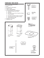
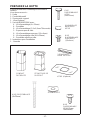
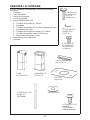
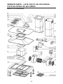
PREPARE THE HOOD
Unpack hood and check contents.
You should receive:
1 - Hood
1 - Decorative Flue Assembly
1 - Support Frame
1 - Glass Frame (Optional)
1 - Parts Bag (B080810504) containing:
4 - Mounting Screws (6 x 70mm)
4 - Washers
8 - Mounting Screws (3,9 x 9,5mm Pan Head)
3 - Glass Brackets
8 - Brackets Mounting Screws (3,9 x 6mm)
6 - Glass Mounting Screws (M4 x 20mm)
6 - Glass Adhesive Pads
1 - Installation Instructions
1 - Warranty Card
4 MOUNTING
SCREWS
(6x70mm)
SUPPORT
FRAME
DECORATIVE
FLUE
GLASS FRAME
(Optional)
4 WASHERS
8 MOUNTING
SCREWS
(3,9x9,5mm
Pan Head)
3 GLASS
BRACKETS
6 GLASS
MOUNTING
SCREWS
(M4x20mm)
6 GLASS
ADHESIVE
PADS
8 BRACKETS
MOUNTING
SCREWS
(3,9x6mm)

- 6 -
MOUNTING
SCREWS
(6x70mm)
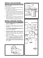
INSTALL THE DUCTWORK
NOTE: To reduce the risk of fire, use only
metal ductwork.
1.Decide where the ductwork will run between
the hood and the outside.
2. A straight, short duct run will allow the hood
to perform most efficiently.
3. Long duct runs, elbows, and transitions will
reduce the performance of the hood. Use
as few of them as possible. Larger ducting
may be required for best performance with
longer duct runs.
4. Install a roof or wall cap. Connect round
metal ductwork to cap and work back to-
wards hood location. Use duct tape to seal
the joints between ductwork sections.
HOOD
ROUND
ELBOW
ROUND
DUCT
ROOF CAP
DECORA-
TIVE
FLUE
TOP VIEW OF SUPPORT FRAME
24” TO 30” ABOVE
COOKING SURFACE
SUPPORT
FRAME
OPENINGS
EAVE
VENT
CROSS FRAMING
9-13/16”
9-13/16”
INSTALL SUPPORT SYSTEM
1. At hood location, install 2 x 4 cross framing
between ceiling joists using dimensions
shown on center.
2. Finish the ceiling surface. Be sure to mark
the location of the ceiling joists and cross
framing.
3. Position the support frame as shown. The
UP ARROW should point towards the
ceiling after installation.
4. Secure the support frame to joists and cross
framing with four screws (6x70mm) and
washers provided. Make sure screws are
driven into center of joists and framing for
maximum strength.
5. Adjust the overall height of the support
frame. Loosen and re-tighten the screws
in the height adjustment slots as
necessary. Note that the hood height is 14-
3/16” (360mm) and that the bottom of the
hood must be 24” min. and 30” max. above
the cooktop.
6” ADAPTER
CEILING
JOISTS
CROSS FRAMING
HEIGHT
ADJUSTMENT
SLOTS
SUPPORT
FRAME
9
13
/16”
DRYWALL
WASHERS
(Ø6.4mm)
FRONT

- 7 -
14-3/16”
min 24”
max 30”
HEIGHT
ADJUSTEMENT
SLOTS
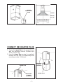
CONNECT DECORATIVE FLUE
1. Secure the upper flue to the support frame
with the mounting screws 3.9x6mm (air
vents must be up).
2. Insert the lower flue moving it completely
towards the top and fix it temporarily with
mounting screws (3.9x6mm).
UPPER FLUE
MOUNTING
SCREWS
(3.9x9.5mm)
RETAINING
SCREWS
(3.9x6mm)
LOWER FLUE

- 8 -
Non-ducted recirculation configuration
Purchase a Non-ducted recirculation KIT
from your dealer (Model NDIS170).
1. Insert the non-ducted recirculation plenum
through the support frame openings.
Secure the non-ducted recirculation
plenum using two (2) brackets and four (4)
mounting screws (3.9x9.5mm).
Fix a flexible duct to the duct connector of
the non-ducted recirculation plenum.
2. Secure the upper flue to the support frame
with the mounting screws 3.9x9.5mm (air
vents must be up).
3. Insert the lower flue moving it completely
towards the top and fix it temporarily with
mounting screws (3.9x6 mm).
UPPER FLUE
MOUNTING
SCREWS
(3.9x9.5mm)
RETAINING
SCREWS
(3.9x6mm)
LOWER FLUE
NON-DUCTED
RECIRCULATION
PLENUM
FLEXIBLE
DUCT
DUCT
CONNECTOR
BRACKETS
MOUNTING
SCREWS
(3.9x9.5mm)

- 9 -
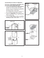
INSTALLATION OF GLASS
FRAME (Optional)
Purchase a Glass Frame from your dealer
(Model GSIS170).
1. Fit the glass frame above the hood.
2. Fit the supplied adhesive pads on the glass
frame in correspondence to its fixing screws
in order to prevent the glass from breaking.
3. Fix the (3) supplied brackets to the hood
with mounting screws (3.9x6mm).
4. Adjust the position of the glass frame and
fix it by means the mounting screws
(M4x20mm).
Please be very careful not to hit the glass
with any objects made of porcelain, metal,
glass or anything else that is very heavy.
GLASS FRAME
SUPPLIED
BRACKETS
ADHESIVE
PADS
MOUNTING SCREWS (M4x20mm)
CONNECT DUCTWORK
1. Position the hood near the lower part of
the support frame and connect the duct to
the duct collar.
2. Use 6" round metal duct to connect the
duct collar on the hood to the ductwork
above.
3. Use duct tape to make all joints secure and
air tight.
DUCT 6”
DUCT COLLAR
MOUNTING SCREWS
(3.9x6mm)

- 10 -
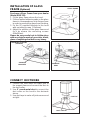
MOUNT HOOD TO SUPPORT
FRAME
1. Install the hood to support frame by (6)
mounting screws (3.9x9.5mm), minding
that the controls are on the proper side.
2. Make electrical connections (refer to the
section “WIRING”).
3. Remove the two temporary fixing screws
of the lower flue and set it in place on the
hood.
MOUNTING
SCREWS
(3.9X9.5MM)
WIRING
Note: This range hood must be properly
grounded. The unit should be installed by a
qualified electrician in accordance with all
applicable national and local electrical
codes.
1. Remove the wiring box cover. Remove a
knockout from the wiring box.
2. Feed 6" of power cable through the knock-
out opening and secure cable to the wiring
box with an appropriate connector.
3. Make electrical connections. Connect
white to white, black to black and green to
green.
4. Replace wiring box cover and screws.
Make sure that wires are not pinched
between cover and box.
WIRING BOX
COVER
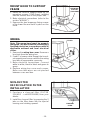
NON-DUCTED
RECIRCULATION FILTER
INSTALLATION
1. Purchase a charcoal filter (FILTER
SQUARE - cod.B03300488) from your
dealer.
2. Install the charcoal filter by pressing the 2
tabs on the filter down into the special
housing and rotating upward.
CHARCOAL
FILTER

- 11 -
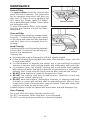
MAINTENANCE
Grease Filters
The grease filters should be cleaned after
every 30 hours of operation. This range hood
has an operation timer which will alert you
after every 30 hours of use by lighting a red
LED above the “blower speed 0-1 button”.
Use a warm detergent solution. Grease filters
are dishwasher safe.
To take off the grease filters: at the handle,
push the stop inwards and pull the filters
downwards.
Charcoal Filter
The charcoal filter should be changed every
6 months. To remove the filter press inward
on the clamp and rotate the filter downward
until the 2 tabs can be removed from the
housing.
Hood Cleaning
Stainless steel is one of the easiest materials
to keep clean. Occasional care will help pre-
serve its fine appearance.
Cleaning tips:
O Hot water with soap or detergent is all that is usually needed.
O Follow all cleaning by rinsing with clear water. Wipe dry with a clean, soft cloth
to avoid water marks.
O For discolorations or deposits that persist, use a non-scratching household
cleanser or stainless steel polishing powder with a little water and a soft cloth.
O For stubborn cases, use a plastic scouring pad or soft bristle brush together
with cleaser and water. Rub lightly in direction of polishing lines or "grain" of the
stainless finish. Avoid using too much pressure which may mar the surface.
O DO NOT allow deposits to remain for long periods of time.
O DO NOT use ordinary steel wool or steel brushes. Small bits of steel may
adhere to the surface causing rust.
O DO NOT allow salt solutions, disinfectants, bleaches, or cleaning compounds
to remain in contact with stainless steel for extended periods. Many of these
compounds contain chemicals which may be harmful. Rinse with water after
exposure and wipe dry with a clean cloth.
Painted surfaces should be cleaned with warm water and mild detergent only.
Glass Cleaning
Use a soft cloth and a glass cleaning solution only!
DO NOT use abrasive cloths, steel wool, or scouring pads.
DO NOT use strong cleaning solutions or abrasive powders.
GREASE FILTERS
TABS
CLAMP

- 12 -
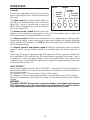
OPERATION
Controls
The hood is operated using the (5) push-but-
tons located at eye-level, on the front edge of
the hood.
The light switch turns the halogen lights on
and off. Push the light switch once to turn the
lights ON - push a second time to turn the
lights ON to a brighter level - push a third time
to turn the lights OFF.
The blower on-off / speed 1 switch turns the
blower on to its lowest running speed. To turn OFF the blower, push in and hold
this blower switch for approximately 2 seconds.
The blower speed 2 switch turns the blower on to medium-low running speed.
Pressing this switch a second time sets a timer which keeps the blower operating
at this speed for 10 minutes. The LED will blink during this time and the blower will
shut off automatically.
The blower speed 3 and blower speed 4 switches operate the same as blower
speed 2 switch except: Blower speed 3 is medium-high and blower speed 4 is
high.
After every 30 hours of operation, the LED above the “blower speed 1 switch” will
be illuminated (RED) and blink for 30 seconds after turning off the blower. This is
a reminder to clean the grease filters. Once the grease filters are cleaned and
installed, press in and hold the “light switch” button for approximately 2 seconds
during the blink of the LED.
HEAT SENTRY™
Your hood is equipped with a HEAT SENTRY™ thermostat. This thermostat is a
device that will turn on or speed up the blower if it senses excessive heat above
the cooking surface.
1) If blower is OFF - it turns blower ON to HIGH speed.
2) If blower is ON at a lower speed setting - it turns blower up to HIGH speed.
When the temperature level drops to normal, the blower will return to its original
setting.
WARNING
The HEAT SENTRY thermostat can start the blower even if the hood is turned
OFF. When this occurs, it is impossible to turn the blower OFF with its switch.
If you must stop the blower, do it from the main electrical panel.
BLOWER
ON-OFF /
SPEED 1
0-1
23
4
LED
LED
LED
LED
BLOWER
SPEED 4
LIGHT
SWITCH
BLOWER
SPEED 2
BLOWER
SPEED 3

- 13 -
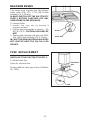
FUSE REPLACEMENT
SWITCH OFF THE ELECTRICITY SUPPLY.
To lift the lower flue.
Open the electrical box.
Replace with the same type of fuse (5x20mm,
5A, 125V).
ELECTRICAL
BOX
FUSE
HALOGEN BULBS
This range hood requires four (4) halogen
bulbs (max 20W, 12V, TYPE MR16 bulb
shielded, GU 5.3 Base).
ALWAYS SWITCH OFF THE ELECTRICITY
SUPPLY BEFORE CARRYING OUT ANY
OPERATIONS ON THE APPLIANCE.
To change bulbs:
1. Loosen the ring nut by turning it
counterclockwise.
2. Pull the bulb downwards to remove - DO
NOT ROTATE. CAUTION: BULB MAY BE
HOT!
3. Replace with halogen bulb type max 20W,
12V, MR16 bulb shielded, GU 5.3 Base.
IN CASE THE NEW HALOGEN BULB DOES
NOT LIGHT UP ONCE IT IS ON, CALL FOR
SERVICE.
BULB
RING NUT

- 14 -
WARRANTY
BROAN ONE YEAR LIMITED WARRANTY
Broan warrants to the original consumer purchaser of its products that such products will be free from defects in materials
or workmanship for a period of one year from the date of original purchase. THERE ARE NO OTHER WARRANTIES,
EXPRESS OR IMPLIED, INCLUDING, BUT NOT LIMITED TO, IMPLIED WARRANTIES OR MERCHANT ABILITY OR
FITNESS FOR A PARTICULAR PURPOSE.
During this one-year period, Broan will, at its option, repair or replace, without charge, any product or part which is found to
be defective under normal use and service.
THIS WARRANTY DOES NOT EXTEND TO FLUORESCENT LAMP STARTERS, TUBES, HALOGEN AND
INCANDESCENDT BULBS. This warranty does not cover (a) normal maintenance and service or (b) any products or parts
which have been subject to misuse, negligence, accident, improper maintenance or repair (other than by Broan), faulty
installation or installation contrary to recommended installation instructions.
The duration of any implied warranty is limited to the one-year period as specified for the express warranty. Some states do
not allow limitation on how long an implied warranty lasts, so the above limitation may not apply to you.
BROAN’S OBLIGATION TO REPAIR OR REPLACE, AT BROAN’S OPTION, SHALL BE THE PURCHASER’S SOLE AND
EXCLUSIVE REMEDY UNDER THIS WARRANTY. BROAN SHALL NOT BE LIABLE FOR INCIDENTAL, CONSEQUEN-
TIAL OR SPECIAL DAMAGES ARISING OUT OF OR IN CONNECTION WITH PRODUCT USE OR PERFORMANCE.
Some states do not allow the exclusion or limitation of incidental or consequential damages, so the above limitation or
exclusion may not apply to you.
This warranty gives you specific legal rights, and you may also have other rights, which vary from state to state. This warranty
supersedes all prior warranties.
To qualify for warranty service, you must (a) notify Broan at the address stated below or telephone: 1-800-637-1453, (b) give
the model number and part identification and (c) describe the nature of any defect in the product or part. At the time of requesting
warranty service, you must present evidence of the original purchase date.
BEST BY BROAN, P.O. Box 140 Hartford, Wisconsin 53027

- 15 -
LISEZ ET CONSERVEZ CES INSTRUCTIONS
AVERTISSEMENTS
POUR REDUIRE LES RISQUES D’INCENDIE, DE DECHARGES ELECTRIQUES OU
DE DOMMAGES AUX PERSONNES, OBSERVEZ LES INSTRUCTIONS SUIVANTES:
1. N’utilisez cet appareil que comme cela est indiqué par le constructeur. Si vous avez des
problèmes, contactez le fabriquant à l’adresse ou au numéro de téléphone indiqués dans
la garantie.
2. Avant de pourvoir à l’entretien ou au nettoyage de votre appareil, éteignez-le au tableau
des commandes ou bloquez le tableau des commandes afin d’éviter de le mettre en marche
accidentellement. Si vous ne pouvez pas bloquer le système permettant d’éteindre votre
appareil, appliquez un avertissement extérieur d’une façon sure, comme par exemple un
panneau, sur le tableau des commandes.
3. L’assemblage et la connexion électrique doivent être faits par des personnes qualifiées
en respectant les normes et règlements en vigueur, y compris les normes et règlements
concernant les possibilités d’incendie.
4. Il est indispensable qu’il y ait suffisamment d’air pour que la combustion et l’évacuation des
gaz à travers le tuyau du brûleur du combustible ait lieu sans retour de flamme. Suivez
les indications données par le fabricant du brûleur ainsi que les normes de sécurité comme
celles qui sont publiées par l’Association Nationale pour la Protection contre les Incendies
National Fire Protection Association (NFPA) et la American Society for Heating, Refrigeration
and Air Conditioning Engineers (ASHRAE), et les autorités locales en matière de normes.
5. Quand vous coupez ou percez des trous dans le mur ou le plafond, n’abîmez pas les fils
électriques ou autres.
6. Le ventilateur canalisé doit toujours évacuer l’air vers l’extérieur.
7. N’utilisez pas cet appareil avec un appareil contrôlant la vitesse à état solide.
8. Afin de diminuer tout risque d’incendie n’utilisez que des conduits en métal.
9. Votre appareil doit être relié à la terre.
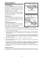
ATTENTION - POUR REDUIRE LES RISQUES D’INCENDIE DES MATIERES GRASSES
QUI SONT EN TRAIN DE CUIRE:
A. Ne laissez jamais ni vos éléments chauffants, ni vos casseroles ou poêles sur le feu
sans les contrôler si vous réglez l’apport de chaleur sur une position élevée. Si vos
casseroles ou poêles débordent cela provoque de la vapeur et des éclaboussures de
graisse qui peuvent prendre feu. Chauffez les huiles lentement à feu bas ou moyen.
B. Faites toujours fonctionner votre hotte quand vous cuisez à des températures élevées
ou quand vous cuisinez des plats flambés. (par ex. crêpes Suzette, Cerises “Jubilé”,
Steack au poivre flambé).
C. Nettoyez régulièrement les ailes de vos ventilateurs. Ne permettez pas que la graisse
s’accumule sur le ventilateur ou sur le filtre.
D. Utilisez des casseroles de taille appropriée. Utilisez toujours des ustensiles de cuisson
dont la taille est appropriée à la surface de votre élément de cuisson.
AVERTISSEMENTS
POUR REDUIRE LES RISQUES DE DOMMAGES AUX PERSONNES AU CAS OÙ VOTRE
CUISINIERE PRENDRAIT FEU, OBSERVEZ LES INSTRUCTIONS SUIVANTES:*
1. ETEINDRE LES FLAMMES à l’aide d’un couvercle le plus hermétique possible, une
plaque à gâteaux, ou un plateau en métal, puis éteindre le brûleur. ATTENTION à NE
PAS VOUS BRÛLER. Si les flammes ne s’éteignent pas immédiatement, SORTEZ ET
APPELEZ LES POMPIERS.
2. NE PRENEZ JAMAIS EN MAIN UNE POÊLE OU UNE CASSEROLE QUI A PRIS FEU
- Vous pourriez vous brûler.
3. N’UTILISEZ PAS D’EAU, ni torchons ou serviettes mouillés - vous provoqueriez une
violente explosion de vapeur.
SEULEMENT POUR UTILISATION DOMESTIQUE
!
!

- 16 -
4. Utilisez un extincteur SEULEMENT si:
A. Vous savez que vous avez un extincteur Classe ABC, et vous en connaissez déjà le
mode d’emploi.
B. Ce n’est pas un très gros incendie et qu’il se limite à l’endroi où il a explosé.
C. Vous êtes en train d’avertir les pompiers.
D. Vous avez la possibilité d’essayer d’éteindre l’incendie en ayant le dos tourné vers
une issue.
* D’après les “Suggestions concernant la Sécurité contre les incendies des cuisines”
publiées par NFPA.
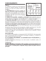
ATTENTION
1. Pour réduire tout risque d’incendie et pour évacuer correctement l’air, assurez-vous de
prévoir un conduit de ventilation extérieur. Ne videz pas l’air dans les espaces limités
par des murs ou des plafonds, les combles, les passages étroits ou les garages.
2. Faites très attention quand vous utilisez des produits de nettoyage ou des détergents.
3. Évitez d’utiliser des aliments pouvant s’enflammer sous la Range Hood.
4. N’utilisez cet appareil que pour une ventilation générale. Ne l’utilisez pas pour évacuer
des matières ou des vapeurs dangereuses ou qui peuvent exploser.
5. Pour éviter de causer des dommages au moteur et de rendre les rotors bruyants et/ou
non équilibrés, évitez que les sprays pour murs secs, la poussière de construction
entrent en contact avec la partie électrique.
6. Le moteur de votre hotte a un thermostat qui éteindra automatiquement le moteur s’il est
surchauffé. Le moteur se remettra en marche lorsqu’il se sera refroidi. Si le moteur
continue à s’éteindre et à se remettre en marche, faites vérifier votre hotte.
7. Pour mieux capturer les impuretés de cuisine, le bas de votre hotte devrait être à une
distance minimum de 24” et à une distance maximum de 30” au-dessus du plan de
cuisson.
8. Vu que cette hotte est grande et lourde, il est recommandé de confier l’installation de
cette hotte à 3 personnes.
9. Ce produit est doté d’un thermostat qui active automatiquement le moteur. Pour
réduire le risque de dommages et éviter l’activation accidentelle, positionner l’interrupteur
du panneau de service sur la position OFF et bloquer le panneau de service ou mettre
un avertissement externe, par exemple une plaquette.
10. Utiliser uniquement avec un kit de connexion pour alimentation homologué.
11. Nous vous recommandons de lire l’étiquette indiquant les caractéristiques de votre
hotte pour de plus amples informations et exigences.
!

- 17 -
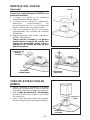
PREPAREZ LA HOTTE
Enlever la hotte dans l’emballage et controller le
contenu.
Vous devez recevoir :
1 - Hotte
1 - Conduit décoratif
1 - Structure de support
1 - Vitre (Optione)
1 - Sachet (B080810504) avec:
4 - Vis d’assemblage (6 x 70mm)
4 - Rondelles
8 - Vis d’assemblage (3,9 x 9,5mm Tête ronde)
3 - Equerres pour la vitre
8 - Vis d’assemblage equerres (3,9 x 6mm)
6 - Vis d’assemblage vitre (M4 x 20mm)
6 - Rondelles adhesives vitre
1 - Instructions pour l’installation
1 - Garantie
4 VIS D’ASSEMBLAGE
(6x70mm)
STRUCTURE DE
SUPPORT
CONDUIT
DECORATIF
VITRE (Optional)
4 RONDELLES
8 VIS
D’ASSEMBLAGE
(3,9x9,5mm
Tête ronde)
3 EQUERRES
POUR LA VITRE
6 VIS
D’ASSEMBLAGE
VITRE
(M4x20mm)
6 RONDELLES
ADHESIVES
VITRE
8 VIS
D’ASSEMBLAGE
EQUERRES
(3,9x6mm)

- 18 -
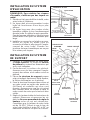
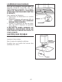
INSTALLATION DU SYSTEME
D’EVACUATION
REMARQUE: Pour réduire les risques
d’incendie, n’utilisez que des tuyaux en
métal.
1. Décidez où le tuyau doit être installé, entre
votre hotte et l’extérieur.
2. Un tuyau droit et court permettra à votre
hotte de fonctionner d’une façon plus
efficace.
3. Un tuyau long avec des coudes et des
transitions réduira le bon fonctionnement
de votre hotte. En utiliser le moins possible.
Pour de longues utilisations, il faut un tuyau
d’évacuation d’air ayant un diamètre plus
large.
4. Installez un couvercle sur le toit ou au mur.
Reliez un tuyau en métal rond au
couvercle et faites-le aller jusqu’à l’empla-
cement de votre hotte. Rendez les
jonctions du tuyau hermétiques au moyen
d’un ruban pour tuyaux.
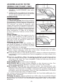
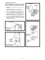
INSTALLATION DU SYSTEME
DE SUPPORT
1. Installez, à l’emplacement de votre hotte,
un cadre croisé de 2 x 4 entre les solives
du plafond en suivant les dimensions qui
vous sont indiquées.
2. Perfectionnez la surface du plafond.
Assurez-vous de bien marquer l’empla-
cement des solives et du cadre croisé au
plafond.
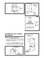
3. Placez la structure de support comme
cela est indiqué. Après avoir fait la fixation,
la flèche doit braquer sur le plafond.
4. Fixez la structure de support aux solives et
au cadre croisé au moyen des quatre vis
(6x70mm) et rondelles qui vous sont
fournies. Assurez-vous que les vis soient
bien centrées dans les solives et dans le
cadre croisé de sorte que le tout soit bien
solide.
5. Réglez la hauteur totale de la structure de
support. Désserrez et resserrez les vis
dans les fissures permettant de régler la
hauteur selon ce qui est nécessaire.
Considérez que la hauteur de votre hotte
est de 14-3/16” (36cm) et que le bas de
votre hotte doit être à entre 24” et 30” au
maximum au-dessus du plan de cuisson.
COUVERCLE DU TOIT
TUYAU ROND
HOTTE
CONDUIT
DÉCORATIF
TROU
D’ÉVA-
CUATION
COUDE ROND
6” (15cm)
ADAPTATEUR
DE 24”(61cm) À 30”
(76cm) AU-DESSUS
DU PLAN DE CUISSON
9-13/16”
(25cm)
OUVERTURE
DE LA
STRUCTURE
DE SUPPORT
STRUCTURE
DE SUPPORT
PARTIE
FRONTAL
SURFACE DU
PLAFOND
CADRE CROISÉ
SOLIVES
DU
PLAFOND
FISSURE POUR
RÉGLAGE EN
HAUTEUR
VIS
D’ASSEMBLAGE
(6x70mm)
RONDELLES
(Ø6.4mm)

- 19 -
FISSURE POUR
RÉGLAGE EN
HAUTEUR
14-3/16”
(36cm)
min 24”
max 30”
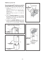
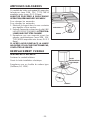
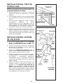
ASSEMBLAGE DU CONDUIT
DECORATIF
Modèle avec tuyau d’évacuation
1. Fixer le conduit supérieur à la structure
de support à l’aide des vis d’assemblage
3.9x9.5mm (les prises d’air doivent être
tournées vers le haut).
2. Installer le conduit inférieur pour qu’il
touche le plafond et le fixer provisoirement
à l’aide des vis d’assemblage (3.9x6mm).
CONDUIT DECORATIF
SUPERIEUR
VIS
D’ASSEMBLAGE
(3.9x9.5mm)
VIS D’ASSEMBLAGE
(3.9x6mm)
CONDUIT
DECORATIF
INFERIEUR
VUE DE HAUT DU CADRE CROISÉ
9-13/16” (25cm)
CADRE CROISÉ
9-13/16”
(25cm)

- 20 -
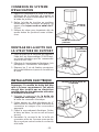
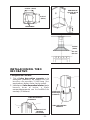
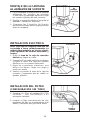
Modèle recyclant l’air
Procurez-vous un KIT version recyclant l’air
(Modele NDIS170) chez votre fournisseur.
1. Enfiler le déflecteur de l’air par les
ouvertures.
Fixer le déflecteur au moyens de 2
equerres et 4 vis d’assemblage
(3.9x9.5mm).
Fixer un tuyau souple à la bride du
déflecteur.
2. Fixer le conduit supérieur à la structure
de support à l’aide des vis d’assemblage
3.9x9.5mm (les prises d’air doivent être
tournées vers le haut).
3. Installer le conduit inférieur pour qu’il
touche le plafond et le fixer provisoirement
à l’aide des vis d’assemblage (3.9x6mm).
CONDUIT DECORATIF SUPERIEUR
VIS
D’ASSEMBLAGE
(3.9x9.5mm)
VIS
D’ASSEMBLAGE
(3.9x6mm)
CONDUIT DECORATIF
INFERIEUR
DEFLECTEUR
TUYAU
SOUPLE
BRIDE DU
DEFLECTEUR
EQUERRES
VIS
D’ASSEMBLAGE
(3.9x9.5mm)
La page charge ...
La page charge ...
La page charge ...
La page charge ...
La page charge ...
La page charge ...
La page charge ...
La page charge ...
La page charge ...
La page charge ...
La page charge ...
La page charge ...
La page charge ...
La page charge ...
La page charge ...
La page charge ...
La page charge ...
La page charge ...
La page charge ...
La page charge ...
La page charge ...
La page charge ...
La page charge ...
La page charge ...
-
 1
1
-
 2
2
-
 3
3
-
 4
4
-
 5
5
-
 6
6
-
 7
7
-
 8
8
-
 9
9
-
 10
10
-
 11
11
-
 12
12
-
 13
13
-
 14
14
-
 15
15
-
 16
16
-
 17
17
-
 18
18
-
 19
19
-
 20
20
-
 21
21
-
 22
22
-
 23
23
-
 24
24
-
 25
25
-
 26
26
-
 27
27
-
 28
28
-
 29
29
-
 30
30
-
 31
31
-
 32
32
-
 33
33
-
 34
34
-
 35
35
-
 36
36
-
 37
37
-
 38
38
-
 39
39
-
 40
40
-
 41
41
-
 42
42
-
 43
43
-
 44
44


Best IS170 Manuel utilisateur
- Catégorie
- Hottes
- Taper
- Manuel utilisateur
- Ce manuel convient également à
dans d''autres langues
- English: Best IS170 User manual
- español: Best IS170 Manual de usuario