Miller Coolmate V3 Le manuel du propriétaire
- Catégorie
- Système de soudage
- Taper
- Le manuel du propriétaire
Ce manuel convient également à

OWNER’S MANUAL
© 2009 MILLER Electric Mfg. Co.
OM‐618 194 463F
2009−01
CE And Non-CE Models
Use above FORM number when ordering extra manuals.
Coolmate™ V3
1. Specifications
Ref. ST-802 367-A
Recirculating Coolant System For Water-Cooled GTAW Torches And GMAW Guns
Use With Guns/Torches Rated Up To 600 Amperes
IP Rating: 23 − Not Intended For Use In Heavy Rain, Or Near Splashing Water
3 gal (11.4 L) Coolant Tank Capacity;
Maximum Cooling Capacity: 3,820 W (13,000 BTU/hr) @ 4.2 qt/min (4.0 L/min)
IEC Cooling Capacity: 1,420 W (4,840 BTU/hr) @ 1.1 qt/min (1 L/min)
IEC Cooling Capacity States That The Water Inlet Temperature Can Not Exceed 40° C Above Ambient
Temperature At A 1l/ Min Flow Rate.
Dimensions: 12-1/4 in (311 mm) Deep, 9-3/4 in (248 mm) Wide, 33 in (838 mm) High
Weight: 50 lb (23 kg)
115 Volt, 5.9 Amperes 60 Hertz, 4.7 Amperes 50 Hertz, Single−Phase Input Power
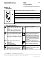
2. Safety Symbol Definitions
DANGER! − Indicates a hazardous situation which, if not
avoided, will result in death or serious injury. The possible
hazards are shown in the adjoining symbols or explained
in the text.
DANGER! − Indique une situation dangereuse qui si on
l’évite pas peut donner la mort ou des blessures graves.
Les dangers possibles sont montrés par les symboles
joints ou sont expliqués dans le texte.
Wear safety glasses with side shields.
Porter des lunettes de sécurité avec des protections laté-
rales.
Indicates a hazardous situation which, if not avoided,
could result in death or serious injury. The possible ha-
zards are shown in the adjoining symbols or explained in
the text.
Indique une situation dangereuse qui si on l’évite pas peut
donner la mort ou des blessures graves. Les dangers possi-
bles sont montrés par les symboles joints ou sont expliqués
dans le texte.
Have only trained and qualified persons install, operate,
or service this unit. Call your distributor if you do not un-
derstand the directions. For WELDING SAFETY and
EMF information, read owner’s manual(s).
L’installation, l’exploitation et l’entretien de cet appareil
doivent être confiés uniquement à des personnes quali-
fiées et convenablement formées. S’adresser à un distri-
buteur si l’on ne comprend pas les directives. Pour les
renseignements ayant trait à la SECURITE lors du sou-
dage et aux champs électromagnétiques, consulter les
manuels traitant les dévidoirs et les sources de courant
pour le soudage.
NOTICE
Indicates statements not related to personal injury.
Indique des déclarations pas en relation avec des blessu-
res personnelles.
Indicates special instructions.
Indique des instructions spécifiques.
Beware of moving parts. Keep guards and panels in
place, covers closed, and hands away from moving parts.
Attention aux pièces mobiles. Maintenir les dispositifs de
sécurité et les panneaux en place, les couvercles fermés
et garder les mains éloignées des pièces mobiles.
Beware of electric shock from wiring. Disconnect input
power before installing this kit. Reinstall all panels and
covers.
Prendre garde aux chocs électriques dus au câblage.
Avant d’installer cet ensemble, couper l’alimentation.
Réinstaller tous les panneaux et couvercles.
Recycle or dispose of used coolant in an environmentally
safe way.
Recycler ou éliminer tout liquide de refroidissement usé
conformément aux méthodes prescrites pour assurer la
protection de l’environnement.
3. Serial Number And Rating Label Location
The serial number and rating information for this product is located on the back panel. Use rating label to determine input power requirements and/or
rated output. For future reference, write serial number in space provided on cover of this manual.

OM-618 Page 2
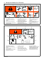
4. Warning Label Definitions For CE Products
S-180 663
1 2 3 4 5
6
7 8 9
1 Warning! Watch Out! There are
possible hazards as shown by the
symbols.
2 Electric shock from wiring can kill.
3 Disconnect input plug or power before
working on machine.
4 Moving parts, such as fans, can cut
fingers and hands and cause injury.
Keep away from moving parts.
5 Wear safety glasses with side shields.
6 Read the Owner’s Manual before
working on this machine.
7 Read the labels on the welding power
source, wire feeder, or other major
equipment for welding safety
information.
8 Recycle or dispose of used coolant in
an environmentally safe way.
9 Do not remove or paint over (cover)
the label.
4/96
S-178 910
=
043 810 (HF)
043 809 (AL)
100 h. std.
21 3
6
4
7
5
1 Warning! Watch Out! There are
possible hazards as shown by the
symbols.
2 Disconnect input plug or power before
working on machine.
3 Wear safety glasses with side shields.
4 Plugged filter or hoses cause
overheating and damage.
5 Read Owner’s Manual.
6 Check and clean filter every 100
hours; also check condition of hoses.
7 Use Low Conductivity Coolant No. 043
810 for High-Frequency assisted or
Gas Tungsten Arc Welding
applications. Use Aluminum Protecting
Coolant No. 043 809 where coolant
contacts aluminum parts or for Gas
Metal Arc Welding applications or
where High Frequency is not used.

OM-618 Page 3
5. Symbols And Definitions
. Some symbols are found only on CE products.
A
Amperes Alternating Current Voltage Input
Circulating Unit
With Coolant Pump
V
Volts
Water (Coolant) In-
put
Water (Coolant)
Output
Line Connection
Protective Earth
(Ground)
IP
Degree Of
Protection
I
1
Primary Current
Hz
Hertz
On Off
U
1
Primary Voltage Single Phase
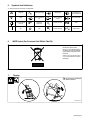
6. WEEE Label (For Products Sold Within The EU)
Do not discard product (where ap-
plicable) with general waste.
Reuse or recycle Waste Electrical
and Electronic Equipment (WEEE)
by disposing at a designated collec-
tion facility.
Contact your local recycling office
or your local distributor for further
information.
7. Tipping
! Do not move or operate unit
where it could tip.
Ref ST-802 055

OM-618 Page 4
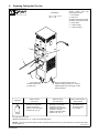
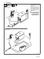
8. Preparing Cooling Unit For Use
Ref. ST-802 367-A
Fittings have 5/8-18 left-hand
threads. Connect hoses with
proper fittings as shown.
1 Flow Indicator
2 Filler Cover
Use table to select proper coolant,
and fill tank. Keep coolant level full.
3 Power Switch
4 Coolant In Fitting
5 Coolant Out Fitting
Tools Needed:
11/16 in
4
5
3
1
2
MILLER Low Conductivity
Coolant No. 043 810**;
Distilled Or Deionized Water
OK Above 32° F (0° C)
MILLER Low Conductivity
Coolant No. 043 810**; Or
MILLER Aluminum Protecting
Coolant No. 043 809**;
Distilled Or Deionized Water
OK Above 32° F (0° C)
GTAW Or Where
HF* Is Used
GMAW Or Where
HF* Is Not Used
Application
*HF: High Frequency Current
**MILLER coolants protect to -37° F (-38°C) and resist algae growth.
Coolant
MILLER Aluminum
Protecting Coolant
No. 043 809**
Where Coolant Contacts
Aluminum Parts
Some models have
Holes are provided in bottom edge of
wrapper for bolting unit (with 1/4 in, customer
supplied hardware) to a running gear or other
permanent location.
two labels instead of one
(see Parts List).
NOTICE − Use of any coolant other than those listed in the table voids the warranty on any parts that come in contact with the coolant
(pump, radiator, etc.).

OM-618 Page 5
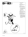
9. Connections
ST-802 368
To prevent overheating, make sure
cooling unit is positioned so airflow
is not restricted.
NOTICE − When using coolant sys-
tem with a welding power source
with a water valve, bypass water
valve on welding power source by
connecting directly to torch/gun to
avoid overheating, or damage to
coolant system.
! To prevent tipping when
placing unit on uneven or tilt-
ing surfaces, properly se-
cure the coolant system to a
wall, stationary support, or
equivalent rigid structure.
GTAW Connections
GMAW Connections

OM-618 Page 6
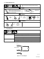
Turn Off and unplug unit.
1 Coolant Pump
2 Filter Cap
Place cloth or suitable container un-
der nut, and remove nut.
3 Strainer
Rinse strainer with clean water.
Reinstall parts. Remove cloth or
container, and reinstall wrapper.
. Relief valve is factory set at 60
psi (414 kPa), and normally
needs no adjustment: Only ad-
just if replacing motor.
4 Pressure Gauge
5 Relief Valve Adjustment
Screw
Connect gauge to Coolant Out fit-
ting as shown. Block or plug any
output fitting on gauge.
Turn On power, and adjust pres-
sure adjustment screw as needed.
Turn Off power. Disconnect gauge
and reinstall nut and wrapper.
. If replacing hoses, use hoses
compatible with ethylene gly-
col, such as Buna-n, Neo-
prene, or Hypalon. Oxy-acety-
lene hoses are not compatible
with any product containing
ethylene glycol.
3/8 in
Tools Needed:
10. Coolant Maintenance
ST-802 369-A
15/16, 3/4 in
1
3
2
5
Decrease Increase
4

OM-618 Page 7
11. Routine Maintenance
! Turn Off all power and unplug unit before maintaining.
1 Month
Blow Out Heat
Exchanger Fins
NOTICE − Clean coolant strainer. Severe condi-
tions may require more frequent cleaning (contin-
uous use, high/low temperatures, dirty environ-
ment, etc.). Failure to properly clean coolant
strainer voids pump warranty.
6 Months
Replace
Cracked
Hoses
Replace
Unreadable
Labels
Change
Coolant (If
Using Water)
12 Months
Change
Coolant (If
Using MILLER
Coolant)
12. Troubleshooting
Trouble Remedy
Coolant system does not work. Be sure input power cord is plugged in to energized receptacle.
Check line fuses or circuit breaker, and replace or reset if necessary.
Motor overheated. Unit starts running when motor has cooled.
Have Factory Authorized Service Agent check Power switch and motor.
Decreased or no coolant flow. Add coolant.
Check for clogged hoses or coolant filter.
Disconnect pump, and check for sheared coupling. Replace coupling if necessary.
SA-135 796-D
BLK
WHT
GRN/YEL
11
12
MOT
PLG1
INPUT POWER
S1
Figure 11-1. Circuit Diagram

OM-618 Page 8
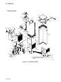
13. Parts List
802 364-D
. Hardware is common and
not available unless listed.
. Some models have two labels
instead of one (check your front
panel).
34/35
36/37
9
11
4B
8
8
33
21
5A
28
11
4A
5B
4B
2
10
5A
5B
4A
2
32
31
22
30
29
27
26
25
24
23
22
20
19
18
17
16
15
14
13
12
7
6
3
1
Figure 12-1. Complete Assembly

OM-618 Page 9
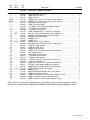
Description
Part
No.
Dia.
Mkgs.
043 009
Item
No.
Figure 12-1. Complete Assembly
Quantity
1 166 608 CAP, tank screw-on w/vent 1. . . . . . . . . . . . . . . . . . . . . . . . . . . . . . . . . . . . . . . . . . . . . . . . . . . . . . . . . .
2 194 179 TUBE, pick-up coolant 1. . . . . . . . . . . . . . . . . . . . . . . . . . . . . . . . . . . . . . . . . . . . . . . . . . . . . . . . . . . . . .
3 192 852 TANK, reservoir 1. . . . . . . . . . . . . . . . . . . . . . . . . . . . . . . . . . . . . . . . . . . . . . . . . . . . . . . . . . . . . . . . . . . .
4A,4B 194 174 TUBING, PVC .375 ID x .625 OD x 15.000 clear brd 2. . . . . . . . . . . . . . . . . . . . . . . . . . . . . . . .
5A,5B 174 044 TUBING, PVC .375 ID x .625 OD x 18.000 clear brd 2. . . . . . . . . . . . . . . . . . . . . . . . . . . . . . . .
6 196 515 RADIATOR, heat exchanger 1. . . . . . . . . . . . . . . . . . . . . . . . . . . . . . . . . . . . . . . . . . . . . . . . . . . . . . . . .
7 197 361 PUMP, coolant (includes) 1. . . . . . . . . . . . . . . . . . . . . . . . . . . . . . . . . . . . . . . . . . . . . . . . . . . . . . . . . . .
8 126 978 FITTING, hose brs barbed M 3/8tbg x 3/8NPT 2. . . . . . . . . . . . . . . . . . . . . . . . . . . . . . . . . . . . . . . . .
9 196 990 FITTING, hose brs barbed 1. . . . . . . . . . . . . . . . . . . . . . . . . . . . . . . . . . . . . . . . . . . . . . . . . . . . . . . . . .
10 134 795 COUPLER, drive pump 1. . . . . . . . . . . . . . . . . . . . . . . . . . . . . . . . . . . . . . . . . . . . . . . . . . . . . . . . . . . . .
11 194 173 HOSE, NPRN brd No. 1 x .375 ID x 21.000 black 1. . . . . . . . . . . . . . . . . . . . . . . . . . . . . . . . . . . . . .
12 MOT 173 263 MOTOR, 1/4hp 115VAC 50/60Hz 1425/1725RPM 1. . . . . . . . . . . . . . . . . . . . . . . . . . . . . . . .
13 166 570 BLADE, fan 9.000 5wg 38deg .500 bore CW AL 1. . . . . . . . . . . . . . . . . . . . . . . . . . . . . . . . . . . . . . . .
14 192 848 BRACKET, mtg motor/pump 1. . . . . . . . . . . . . . . . . . . . . . . . . . . . . . . . . . . . . . . . . . . . . . . . . . . . . . . . .
15 192 856 PLENUM, fan 1. . . . . . . . . . . . . . . . . . . . . . . . . . . . . . . . . . . . . . . . . . . . . . . . . . . . . . . . . . . . . . . . . . . . .
16 192 858 COVER, top 1. . . . . . . . . . . . . . . . . . . . . . . . . . . . . . . . . . . . . . . . . . . . . . . . . . . . . . . . . . . . . . . . . . . . . . .
17 PLG1 192 457 CABLE, power 11ft 5 in 16ga 3/c 1. . . . . . . . . . . . . . . . . . . . . . . . . . . . . . . . . . . . . . . . . . . . . .
18 139 042 BUSHING, strain relief .270/.470 ID x .804mtg hole 1. . . . . . . . . . . . . . . . . . . . . . . . . . . . . . . . . . . . .
19 192 854 CASE SECTION, wrapper 1. . . . . . . . . . . . . . . . . . . . . . . . . . . . . . . . . . . . . . . . . . . . . . . . . . . . . . . . . .
20 192 857 CASE SECTION, main 1. . . . . . . . . . . . . . . . . . . . . . . . . . . . . . . . . . . . . . . . . . . . . . . . . . . . . . . . . . . . .
21 192 449 LABEL, warning/caution 1. . . . . . . . . . . . . . . . . . . . . . . . . . . . . . . . . . . . . . . . . . . . . . . . . . . . . . . . . . . .
22 166 564 FILTER, in-line low profile 100 screen 3/8 hose bar 1. . . . . . . . . . . . . . . . . . . . . . . . . . . . . . . . . . . . .
23 168 254 CLIP, filter mounting 1. . . . . . . . . . . . . . . . . . . . . . . . . . . . . . . . . . . . . . . . . . . . . . . . . . . . . . . . . . . . . . . .
215 279 INDICATOR, flow (includes) 1. . . . . . . . . . . . . . . . . . . . . . . . . . . . . . . . . . . . . . . . . . . . . . . . . . . . . . . . . . . .
24 186 004 HOUSING, flow indicator 1. . . . . . . . . . . . . . . . . . . . . . . . . . . . . . . . . . . . . . . . . . . . . . . . . . . . . . . . . . . .
25 215 270 PADDLE, flow indicator 1. . . . . . . . . . . . . . . . . . . . . . . . . . . . . . . . . . . . . . . . . . . . . . . . . . . . . . . . . . . . .
26 166 566 O-RING, 1.301 ID x .070 CS 70 Duro Buna−N1. . . . . . . . . . . . . . . . . . . . . . . . . . . . . . . . . . . . . . . . .
27 186 005 LENS, flow indicator 1. . . . . . . . . . . . . . . . . . . . . . . . . . . . . . . . . . . . . . . . . . . . . . . . . . . . . . . . . . . . . . . .
28 166 560 RING, rtng ext .500 shaft x .042thk E style bowed 2. . . . . . . . . . . . . . . . . . . . . . . . . . . . . . . . . . . . . .
29 166 571 FITTING, coolant barbed 3/8tbg 5/8-18 female 2. . . . . . . . . . . . . . . . . . . . . . . . . . . . . . . . . . . . . . . . .
30 193 710 NAMEPLATE, (order by model and serial number) 1. . . . . . . . . . . . . . . . . . . . . . . . . . . . . . . . . . . . .
31 S1 177 396 SWITCH, rocker DPST 15A 250VAC 1. . . . . . . . . . . . . . . . . . . . . . . . . . . . . . . . . . . . . . . . . . . . .
32 +192 859 PANEL, front 1. . . . . . . . . . . . . . . . . . . . . . . . . . . . . . . . . . . . . . . . . . . . . . . . . . . . . . . . . . . . . . . . . . . . .
33 177 448 WEATHERSTRIPPING, adh .250 x .375 x 8.500 2. . . . . . . . . . . . . . . . . . . . . . . . . . . . . . . . . . . . . . .
34 134 327 LABEL, warning (with words) 1. . . . . . . . . . . . . . . . . . . . . . . . . . . . . . . . . . . . . . . . . . . . . . . . . . . . . . . .
35 180 663 LABEL, warning general precautionary (wordless for CE) 1. . . . . . . . . . . . . . . . . . . . . . . . . . . . . . . .
36 188 980 LABEL, caution incorrect coolant (with words) 1. . . . . . . . . . . . . . . . . . . . . . . . . . . . . . . . . . . . . . . . .
37 178 910 LABEL, caution incorrect coolant (wordless for CE) 1. . . . . . . . . . . . . . . . . . . . . . . . . . . . . . . . . . . . .
+When ordering a component originally displaying a precautionary label, the label should also be ordered.
BE SURE TO PROVIDE MODEL AND SERIAL NUMBER WHEN ORDERING REPLACEMENT PARTS.

Notes

242093‐A
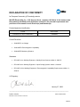
DECLARATION OF CONFORMITY
for European Community (CE marked) products.
MILLER Electric Mfg. Co., 1635 Spencer Street, Appleton, WI 54914 U.S.A. declares that
the product(s) identified in this declaration conform to the essential requirements and
provisions of the stated Council Directive(s) and Standard(s).
Product/Apparatus Identification:
Product Stock Number
COOLMATE V3 W/CE COMPLIANCE 043009012
Council Directives:
• 2006/95/EC Low Voltage
• 2004/108/EC Electromagnetic Compatibility
• 2006/42/EEC Machinery Directive
Standards:
• IEC 609741 Arc Welding Equipment Welding Power Sources: edition 3, 200507.
• IEC 609742 Arc Welding Equipment Liquid Cooling Systems: edition 1, 200206.
• IEC 6097410 Arc Welding Equipment Electromagnetic Compatibility Requirements: edition 1.1,
200410.
US Signatory:
January 27, 2009
__________________________________________________________________________
David A. Werba
Date of Declaration
MANAGER, PRODUCT DESIGN COMPLIANCE

Notes
-
 1
1
-
 2
2
-
 3
3
-
 4
4
-
 5
5
-
 6
6
-
 7
7
-
 8
8
-
 9
9
-
 10
10
-
 11
11
-
 12
12


Miller Coolmate V3 Le manuel du propriétaire
- Catégorie
- Système de soudage
- Taper
- Le manuel du propriétaire
- Ce manuel convient également à
dans d''autres langues
- English: Miller Coolmate V3 Owner's manual
Documents connexes
-
Miller Coolmate V3 Le manuel du propriétaire
-
-
-
-
Miller Coolmate 3 Le manuel du propriétaire
-
-
Miller ARCCOOL V3 Le manuel du propriétaire
-
-
-