
BEDIENUNG UND INSTALLATION
OPERATION AND INSTALLATION
UTILISATION ET INSTALLATION
GEBRUIK EN INSTALLATIE
OBSLUHA A INSTALACE
OBSŁUGA I INSTALACJA
ЭКСПЛУАТАЦИЯ И УСТАНОВКА
KEZELÉS ÉS TELEPÍTÉS
OBSLUHA A INŠTALÁCIA
Offener (druckloser) Warmwasser-Kleinspeicher| Open vented (non-pressurised) small water heater|
Petit chauffe-eau à écoulement libre (pression nulle)| Open (drukloze) kleine warmwaterboiler|
Malý beztlakový zásobníkový ohřívač vody | Bezciśnieniowy mały pojemnościowy ogrzewacz wody|
Открытый (безнапорный) компактный накопительный водонагреватель | Nyílt-rendszerű (nyomásmentes)
kisméretű melegvíztároló| Otvorený (beztlakový) malý zásobník na teplú vodu
» ESH 10 U-N Trend
» ESH 10 O-N Trend

2 | ESH 10 U-N Trend | ESH 10 O-N Trend www.stiebel-eltron.com
INHALT | BESONDERE HINWEISE
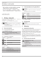
BESONDERE HINWEISE
- Das Gerät kann von Kindern ab 8 Jahren sowie
von Personen mit verringerten physischen,
sensorischen oder mentalen Fähigkeiten oder
Mangel an Erfahrung und Wissen benutzt
werden, wenn sie beaufsichtigt werden oder
bezüglich des sicheren Gebrauchs des Gerätes
unterwiesen wurden und die daraus resultie-
renden Gefahren verstanden haben. Kinder
dürfen nicht mit dem Gerät spielen. Reini-
gung und Benutzer-Wartung dürfen nicht von
Kindern ohne Beaufsichtigung durchgeführt
werden.
- Bei festem Anschluss an das Stromnetz über
eine Geräteanschlussdose muss das Gerät
über eine Trennstrecke von mindestens 3mm
allpolig vom Netzanschluss getrennt werden
können.
- Das Anschlusskabel darf bei Beschädigung
oder Austausch nur durch einen vom Her-
steller berechtigten Fachhandwerker mit dem
originalen Ersatzteil ersetzt werden.
- Schließen Sie das Gerät nicht über eine Zeit-
schaltuhr an.
- Befestigen Sie das Gerät wie in Kapitel „Ins-
tallation/ Montage“ beschrieben.
- Beim Aufheizen tropft das Ausdehnungswas-
ser aus dem Armaturenauslauf.
- Das Gerät darf nur mit einer offenen (drucklo-
sen) Armatur installiert werden.
- Setzen Sie das Gerät keinem Wasserdruck
aus.
- Der Auslauf der Armatur hat die Funktion
einer Belüftung. Kalk kann den Auslauf ver-
schließen und das Gerät unter Druck setzen.
- Verschließen Sie niemals den
Armaturenauslauf.
- Verwenden Sie nur spezielle Strahlregler für
drucklose Warmwasserspeicher.
- Verwenden Sie keinen Schlauch zur Verlänge-
rung des Armaturenauslaufs.
BESONDERE HINWEISE
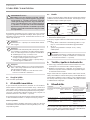
BEDIENUNG
1. Allgemeine Hinweise ����������������������������������������3
1.1 Sicherheitshinweise ��������������������������������������������� 3
1.2 Andere Markierungen in dieser Dokumentation ���������� 3
1.3 Maßeinheiten ����������������������������������������������������� 3
2. Sicherheit �����������������������������������������������������3
2.1 Bestimmungsgemäße Verwendung ������������������������� 3
2.2 Allgemeine Sicherheitshinweise ������������������������������ 3
2.3 Prüfzeichen ������������������������������������������������������� 4
3. Gerätebeschreibung �����������������������������������������4
3.1 Bedienung��������������������������������������������������������� 4
4. Reinigung, Pflege und Wartung ����������������������������4
5. Problembehebung �������������������������������������������5
INSTALLATION
6. Sicherheit �����������������������������������������������������5
6.1 Allgemeine Sicherheitshinweise ������������������������������ 5
6.2 Vorschriften, Normen und Bestimmungen ����������������� 5
7. Gerätebeschreibung �����������������������������������������5
7.1 Lieferumfang ����������������������������������������������������� 5
7.2 Zubehör ������������������������������������������������������������ 5
8. Vorbereitungen ����������������������������������������������� 5
8.1 Montageort ������������������������������������������������������� 5
9. Montage �������������������������������������������������������6
9.1 Montage des Gerätes ������������������������������������������� 6
9.2 Wasseranschluss ������������������������������������������������� 7
9.3 Elektrischer Anschluss ������������������������������������������ 7
10. Inbetriebnahme ����������������������������������������������7
10.1 Erstinbetriebnahme ��������������������������������������������� 7
10.2 Wiederinbetriebnahme ����������������������������������������� 8
11. Einstellungen �������������������������������������������������8
11.1 Temperaturbegrenzung einstellen ��������������������������� 8
12. Außerbetriebnahme �����������������������������������������8
13. Störungsbehebung �������������������������������������������8
14. Wartung �������������������������������������������������������8
14.1 Gerät entleeren �������������������������������������������������� 8
14.2 Gerät öffnen ������������������������������������������������������ 8
14.3 Gerät entkalken �������������������������������������������������� 9
14.4 Anschlusskabel austauschen ���������������������������������� 9
14.5 Schutzleiter prüfen ���������������������������������������������� 9
14.6 Temperaturfühler im Schutzrohr positionieren ����������� 9
15. Technische Daten ��������������������������������������������� 9
15.1 Maße und Anschlüsse ������������������������������������������ 9
15.2 Elektroschaltplan ����������������������������������������������� 10
15.3 Aufheizdiagramm ����������������������������������������������� 10
15.4 Landesspezifische Zulassungen und Zeugnisse ����������10
15.5 Extreme Betriebs- und Störfallbedingungen �������������� 10
15.6 Angaben zum Energieverbrauch ����������������������������10
15.7 Datentabelle ����������������������������������������������������� 11
GARANTIE | UMWELT UND RECYCLING
BEDIENUNG UND INSTALLATION
Offener (druckloser) Warmwasser-Kleinspeicher

BEDIENUNG
Allgemeine Hinweise
DEUTSCH
www.stiebel-eltron.com ESH 10 U-N Trend | ESH 10 O-N Trend | 3
- Entleeren Sie das Gerät wie in Kapitel „In-
stallation/ Wartung/ Gerät entleeren“
beschrieben.
BEDIENUNG
1. Allgemeine Hinweise
Die Kapitel „Besondere Hinweise“ und „Bedienung“ richten sich
an den Gerätebenutzer und den Fachhandwerker.
Das Kapitel „Installation“ richtet sich an den Fachhandwerker.
Hinweis
Lesen Sie diese Anleitung vor dem Gebrauch sorgfältig
durch und bewahren Sie sie auf.
Geben Sie die Anleitung ggf. an einen nachfolgenden
Benutzer weiter.
1.1 Sicherheitshinweise
1.1.1 Aufbau von Sicherheitshinweisen
!
SIGNALWORT Art der Gefahr
Hier stehen mögliche Folgen bei Nichtbeachtung des Si-
cherheitshinweises.
Hier stehen Maßnahmen zur Abwehr der Gefahr.
1.1.2 Symbole, Art der Gefahr
Symbol Art der Gefahr
Verletzung
Stromschlag
Verbrennung
(Verbrennung, Verbrühung)
1.1.3 Signalworte
SIGNALWORT Bedeutung
GEFAHR Hinweise, deren Nichtbeachtung schwere Verletzungen
oder Tod zur Folge haben.
WARNUNG Hinweise, deren Nichtbeachtung schwere Verletzungen
oder Tod zur Folge haben kann.
VORSICHT Hinweise, deren Nichtbeachtung zu mittelschweren oder
leichten Verletzungen führen kann.
1.2 Andere Markierungen in dieser Dokumentation
Hinweis
Allgemeine Hinweise werden mit dem nebenstehenden
Symbol gekennzeichnet.
Lesen Sie die Hinweistexte sorgfältig durch.
Symbol Bedeutung
Sachschaden
(Geräte-, Folge-, Umweltschaden)
Geräteentsorgung
Dieses Symbol zeigt Ihnen, dass Sie etwas tun müssen.
Die erforderlichen Handlungen werden Schritt für Schritt
beschrieben.
1.3 Maßeinheiten
Hinweis
Wenn nicht anders angegeben, sind alle Maße in Milli-
meter.
2. Sicherheit
2.1 Bestimmungsgemäße Verwendung
Das offene (drucklose) Gerät ist für die Erwärmung von Trinkwas-
ser bestimmt. Das Gerät kann eine Entnahmestelle versorgen.
Das Gerät ist für den Einsatz im häuslichen Umfeld vorgesehen.
Es kann von nicht eingewiesenen Personen sicher bedient wer-
den. In nicht häuslicher Umgebung, z.B. im Kleingewerbe, kann
das Gerät ebenfalls verwendet werden, sofern die Benutzung in
gleicher Weise erfolgt.
Eine andere oder darüber hinausgehende Benutzung gilt als nicht
bestimmungsgemäß. Zum bestimmungsgemäßen Gebrauch ge-
hört auch das Beachten dieser Anleitung sowie der Anleitungen
für eingesetztes Zubehör.
2.2 Allgemeine Sicherheitshinweise
WARNUNG Verbrennung
Die Armatur kann während des Betriebs eine Temperatur
von über 60°C annehmen.
Bei Auslauftemperaturen größer 43°C besteht Verbrü-
hungsgefahr.
!
WARNUNG Verletzung
Den Temperatur-Einstellknopf darf nur der Fachhand-
werker abziehen.
!
!

BEDIENUNG
Gerätebeschreibung
4 | ESH 10 U-N Trend | ESH 10 O-N Trend www.stiebel-eltron.com
!
WARNUNG Verletzung
Das Gerät kann von Kindern ab 8 Jahren sowie von Per-
sonen mit verringerten physischen, sensorischen oder
mentalen Fähigkeiten oder Mangel an Erfahrung und
Wissen benutzt werden, wenn sie beaufsichtigt werden
oder bezüglich des sicheren Gebrauchs des Gerätes un-
terwiesen wurden und die daraus resultierenden Gefah-
ren verstanden haben. Kinder dürfen nicht mit dem Gerät
spielen. Reinigung und Benutzer-Wartung dürfen nicht
von Kindern ohne Beaufsichtigung durchgeführt werden.
Falls Kinder oder Personen mit eingeschränkten körperlichen, sen-
sorischen oder geistigen Fähigkeiten das Gerät benutzen, empfeh-
len wir eine dauerhafte Temperaturbegrenzung. Die Begrenzung
kann der Fachhandwerker einstellen.
!
Sachschaden
Das Gerät und die Armatur sind vom Nutzer vor Frost zu
schützen.
!
Sachschaden
Setzen Sie das Gerät keinem Wasserdruck aus. Der Aus-
lauf der Armatur hat die Funktion einer Belüftung. Kalk
kann den Auslauf verschließen und das Gerät unter Druck
setzen.
Verschließen Sie niemals den Armaturenauslauf.
Verwenden Sie nur spezielle Strahlregler für druck-
lose Warmwasserspeicher.
Verwenden Sie keinen Schlauch zur Verlängerung
des Armaturenauslaufs.
!
Sachschaden
Das Anschließen des Gerätes über eine Zeitschaltuhr
verursacht ein unbeabsichtigtes Rücksetzen des Sicher-
heitstemperaturbegrenzers.
Schließen Sie das Gerät nicht über eine Zeitschaltuhr
an das Stromnetz an.
2.3 Prüfzeichen
Siehe Typenschild am Gerät.
3. Gerätebeschreibung
Das offene (drucklose) Gerät hält ständig den Wasserinhalt mit
der vorgewählten Temperatur bereit. Beim Aufheizen tropft das
Ausdehnungswasser durch die Entnahmearmatur. Das Gerät darf
nur mit Armaturen für offene (drucklose) Warmwasserspeicher
installiert werden (siehe Kapitel „Installation/ Gerätebeschrei-
bung/ Zubehör“).
Je nach Jahreszeit ergeben sich bei verschiedenen Kaltwasser-
temperaturen unterschiedliche maximale Mischwasser- und Aus-
laufmengen.
ThermoStop-Funktion
Die ThermoStop-Funktion (thermische Trennung) beim
ESH10U-NTrend verhindert eine Erwärmung der Armatur im
Standby-Betrieb.
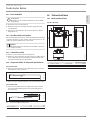
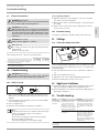
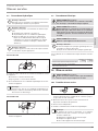
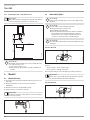
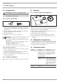
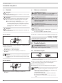
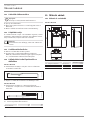
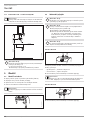
3.1 Bedienung
Die gewünschte Warmwasser-Auslauftemperatur können Sie am
Temperatur-Einstellknopf stufenlos einstellen. Während des Auf-
heizvorgangs leuchtet die Aufheizanzeige.
26�02�06�0154
ESH 10 U-N Trend
ESH 10 O-N Trend
1
2
2
1
1 Aufheizanzeige
2 Temperatur-Einstellknopf
Systembedingt können die Temperaturen vom Sollwert abwei-
chen.
• kalt. Bei dieser Einstellung ist das Gerät vor Frost ge-
schützt. Die Armatur und die Wasserleitung sind nicht
geschützt.
E ca. 40°C
e empfohlene Energiesparstellung (ca. 60°C), geringe
Wassersteinbildung
Hinweis
Der Fachhandwerker kann eine Temperaturbegrenzung
am Gerät vornehmen (siehe Kapitel „Installation/ Einstel-
lungen/ Temperaturbegrenzung einstellen“).
4. Reinigung, Pflege und Wartung
Verwenden Sie keine scheuernden oder anlösenden Reini-
gungsmittel. Zur Pflege und Reinigung des Gerätes genügt
ein feuchtes Tuch.
Kontrollieren Sie regelmäßig die Armatur. Kalk am Armatu-
renauslauf können Sie mit handelsüblichen Entkalkungsmit-
teln entfernen.
Fast jedes Wasser scheidet bei hohen Temperaturen Kalk aus.
Dieser setzt sich im Gerät ab und beeinflusst die Funktion und
Lebensdauer des Gerätes. Die Heizkörper sollten deshalb bei Be-
darf entkalkt werden. Der Fachhandwerker, der die örtliche Was-
serqualität kennt, nennt Ihnen den Zeitpunkt für eine Entkalkung.

INSTALLATION
Problembehebung
DEUTSCH
www.stiebel-eltron.com ESH 10 U-N Trend | ESH 10 O-N Trend | 5
5. Problembehebung
Problem Ursache Behebung
Das Gerät liefert kein
warmes Wasser.
Der Temperatur-Ein-
stellknopf ist auf „
•“
gestellt.
Schalten Sie das Gerät
durch Drehen des Tem-
peratur-Einstellknopfes
ein.
Am Gerät liegt keine
Spannung an.
Prüfen Sie den Stecker/
die Sicherungen in der
Hausinstallation.
Wasser kann nur mit
einer verminderten Zapf-
menge gezapft werden.
Der Strahlregler in der
Armatur ist verkalkt.
Entkalken / erneuern Sie
den Strahlregler.
Starke Siedegeräusche
im Gerät.
Das Gerät ist verkalkt.
Lassen Sie das Gerät
vom Fachhandwerker
entkalken.
Wenn Sie die Ursache nicht beheben können, rufen Sie den Fach-
handwerker. Zur besseren und schnelleren Hilfe teilen Sie ihm die
Nummer vom Typenschild mit (000000-0000-000000).
INSTALLATION
6. Sicherheit
Die Installation, Inbetriebnahme sowie Wartung und Reparatur
des Gerätes darf nur von einem Fachhandwerker durchgeführt
werden.
6.1 Allgemeine Sicherheitshinweise
Wir gewährleisten eine einwandfreie Funktion und Betriebssicher-
heit nur, wenn das für das Gerät bestimmte Original-Zubehör und
die originalen Ersatzteile verwendet werden.
6.2 Vorschriften, Normen und Bestimmungen
Hinweis
Beachten Sie alle nationalen und regionalen Vorschriften
und Bestimmungen.
7. Gerätebeschreibung
Das Gerät ist zur Versorgung einer Entnahmestelle für die Erwär-
mung von Kaltwasser bestimmt.
ESH 10 U-N Trend
Das offene (drucklose) Gerät ist nur für eine Untertischmontage
geeignet.
ESH 10 O-N Trend
Das offene (drucklose) Gerät ist nur für eine Übertischmontage
geeignet.
7.1 Lieferumfang
Mit dem Gerät werden geliefert:
- Wandaufhängung
- Montageschablone
7.2 Zubehör
Für die offene Betriebsweise sind die folgenden Armaturen als
Zubehör erhältlich:
Temperierarmaturen
- WST, WUT
Einhebel-Mischarmaturen
- MEW, MES, MEWC
Sensor-Armatur
- WEN
8. Vorbereitungen
Spülen Sie die Wasserleitung gut durch.
Wasserinstallation
Ein Sicherheitsventil ist nicht erforderlich.
Armaturen
Geschlossene Armaturen sind nicht zulässig.
Montieren Sie eine offene Armatur.
8.1 Montageort
!
Sachschaden
Die Installation des Gerätes darf nur in einem frostfreien
Raum erfolgen.
!
Sachschaden
Montieren Sie das Gerät an die Wand. Die Wand muss
ausreichend tragfähig sein.
Hinweis
Achten Sie darauf, dass das Gerät für Wartungsarbeiten
frei zugänglich ist.
Montieren Sie das Gerät senkrecht und in der Nähe der Entnah-
mestelle.

INSTALLATION
Montage
6 | ESH 10 U-N Trend | ESH 10 O-N Trend www.stiebel-eltron.com
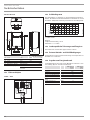
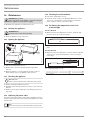
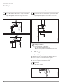
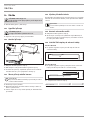
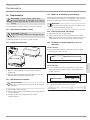
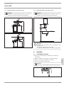
8.1.1 ESH 10 U-N Trend - Untertischmontage
Hinweis
Der ESH 10 U-N Trend ist nur für eine Untertischmontage
geeignet. Die Wasseranschlüsse des Gerätes zeigen nach
oben.
820
520-570
D0000047854
850
550-600
D0000047858
8.1.2 ESH 10 O-N Trend - Übertischmontage
Hinweis
Der ESH 10 O-N Trend ist nur für eine Übertischmontage
geeignet. Die Wasseranschlüsse des Gerätes zeigen nach
unten.
850 200-300
300
D0000047855
!
Sachschaden
Die höchstzulässige Länge der Verbindungsrohre (von der
Armatur zum Gerät) beträgt 1m.
Bei Verbindungsrohren >1m:
Installieren Sie in der Überlaufleitung einen Aufsatz-
rohrbelüfter.
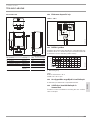
9. Montage
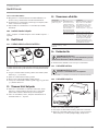
9.1 Montage des Gerätes
Zeichnen Sie die Bohrlöcher mit der beiliegenden Montage-
schablone an.
Bohren Sie die Löcher und setzen Sie geeignete Dübel ein.
Befestigen Sie die Wandaufhängung mit geeigneten
Schrauben.
Hängen Sie das Gerät auf die Wandaufhängung.
Hinweis
Sie können das überschüssige Anschlusskabel in das Ka-
beldepot legen.
26�02�06�0163

INSTALLATION
Inbetriebnahme
DEUTSCH
www.stiebel-eltron.com ESH 10 U-N Trend | ESH 10 O-N Trend | 7
9.2 Wasseranschluss
!
Sachschaden
Führen Sie alle Wasseranschluss- und Installationsarbei-
ten nach Vorschrift aus.
!
Sachschaden
Das Gerät kann undicht und funktionsunfähig werden.
Setzen Sie das Gerät keinem Wasserdruck aus.
Vertauschen Sie nicht die Wasseranschlüsse.
Stellen Sie die Durchflussmenge ein (siehe Anleitung
der Armatur). Beachten Sie die maximal zulässige
Durchflussmenge bei voll geöffneter Armatur (siehe
Kapitel „Installation/ Technische Daten/ Datenta-
belle“).
!
Sachschaden
Beim Festdrehen der Verschraubungen müssen Sie mit
einem geeigneten Schraubenschlüssel gegenhalten.
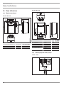
ESH 10 U-N Trend
D0000047852
Ordnen Sie die Farbkennzeichnung der Armaturen-Wasseran-
schlüsse und des Gerätes einander zu:
- Rechts blau = „Kaltwasser Zulauf“
- Links rot = „Warmwasser Auslauf“
Schrauben Sie die Wasseranschlüsse der Armatur fest an das
Gerät.
Hinweis
Achten Sie darauf, dass die Wasseranschlüsse bei der
Montage nicht geknickt werden. Vermeiden Sie Zugspan-
nung beim Einbau.
ESH 10 O-N Trend
D0000047853
Schrauben Sie die Wasseranschlüsse der Armatur fest an das
Gerät.
9.3 Elektrischer Anschluss
WARNUNG Stromschlag
Führen Sie alle elektrischen Anschluss- und Installati-
onsarbeiten nach Vorschrift aus.
WARNUNG Stromschlag
Bei festem Anschluss an das Stromnetz über eine Gerä-
teanschlussdose muss das Gerät über eine Trennstrecke
von mindestens 3mm allpolig vom Netzanschluss ge-
trennt werden können.
WARNUNG Stromschlag
Achten Sie darauf, dass das Gerät an den Schutzleiter
angeschlossen ist.
!
Sachschaden
Die auf dem Typenschild angegebene Spannung muss mit
der Netzspannung übereinstimmen.
Beachten Sie das Typenschild.
Folgende elektrische Anschlussmöglichkeiten sind zulässig:
ESH 10 U-N
Trend
ESH 10 O-N
Trend
Anschluss an eine frei zugängliche Schutzkon-
taktsteckdose mit entsprechendem Stecker
X X
Festanschluss an eine Geräteanschlussdose
mit Schutzleiter
X X
10. Inbetriebnahme
WARNUNG Stromschlag
Die Inbetriebnahme darf nur durch einen Fachhandwer-
ker unter Beachtung der Sicherheitsvorschriften erfol-
gen.
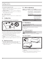
10.1 Erstinbetriebnahme
1. 2.
D0000049325
Öffnen Sie entweder das Warmwasser-Ventil der Armatur
oder stellen Sie den Einhandmischer auf „warm“, bis Wasser
blasenfrei austritt.
Stecken Sie den Stecker in die Schutzkontaktsteckdose oder
schalten Sie die Sicherung in der Hausinstallation ein.
Wählen Sie eine Temperatur.
Prüfen Sie die Dichtheit aller Wasserinstallationen.
Hinweis
Wenn die Reihenfolge (erst Wasser, dann Strom) nicht
eingehalten wird, spricht der Sicherheitstemperaturbe-
grenzer an.
Gehen Sie wie folgt vor:
Trennen Sie das Gerät vom Stromnetz.
Befüllen Sie das Gerät mit Wasser.
Verbinden Sie das Gerät mit dem Stromnetz.

INSTALLATION
Einstellungen
8 | ESH 10 U-N Trend | ESH 10 O-N Trend www.stiebel-eltron.com
10.1.1 Übergabe des Gerätes
Erklären Sie dem Benutzer die Funktion des Gerätes. Machen
Sie ihn mit dem Gebrauch vertraut.
Weisen Sie den Benutzer auf mögliche Gefahren hin, speziell
die Verbrühungsgefahr.
Übergeben Sie diese Anleitung und falls vorhanden die An-
leitungen vom Zubehör.
10.2 Wiederinbetriebnahme
Siehe Kapitel „Installation/ Inbetriebnahme/ Erstinbetriebnah-
me“.
11. Einstellungen
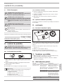
11.1 Temperaturbegrenzung einstellen
26�02�06�0152
Mit dem Hebel auf der Unterseite des Temperatur-Einstellknopfes
können Sie den Einstellbereich des Temperatur-Einstellknopfes auf
eine maximale Temperatur begrenzen.
Drehen Sie den Temperatur-Einstellknopf in Nullstellung (bis
Linksanschlag auf „•“).
Ziehen Sie den Temperatur-Einstellknopf ab.
Stellen Sie den Hebel auf die gewünschte maximale
Temperatur.
Montieren Sie den Temperatur-Einstellknopf in Nullstellung
(•
).
12. Außerbetriebnahme
Trennen Sie das Gerät vom Stromnetz, indem Sie den
Stecker ziehen oder die Sicherung in der Hausinstallation
ausschalten.
Entleeren Sie das Gerät (siehe Kapitel „Installation/ War-
tung/ Gerät entleeren“).
13. Störungsbehebung
Störung Ursache Behebung
Das Gerät liefert kein
warmes Wasser.
Das Gerät wurde nicht
mit Wasser befüllt
und an das Stromnetz
angeschlossen. Die
Reihenfolge der Inbe-
triebnahme wurde nicht
beachtet. Der Sicher-
heitstemperaturbegren-
zer hat ausgelöst.
Ziehen Sie den Netzstecker.
Füllen Sie das Gerät mit Was-
ser. Stecken Sie den Stecker
wieder in die Schutzkontakt-
steckdose (siehe Kapitel „Ins-
tallation/Inbetriebnahme“).
Der Sicherheitstem-
peraturbegrenzer hat
ausgelöst.
Beheben Sie die Fehlerursache.
Erneuern Sie ggf. den Tem-
peraturregler. Lassen Sie das
Gerät abkühlen. Wenn Sie das
Gerät spannungsfrei geschaltet
haben, wird der Sicherheits-
temperaturbegrenzer automa-
tisch zurückgesetzt.
Starke Siedegeräu-
sche im Gerät.
Das Gerät ist verkalkt. Entkalken Sie das Gerät.
14. Wartung
WARNUNG Stromschlag
Trennen Sie bei allen Arbeiten das Gerät allpolig vom
Stromnetz.
Demontieren Sie das Gerät bei Wartungsarbeiten.
14.1 Gerät entleeren
WARNUNG Verbrennung
Beim Entleeren kann heißes Wasser austreten.
Entleeren Sie das Gerät über die Anschlussstutzen.
14.2 Gerät öffnen
26�02�06�0153
Ziehen Sie den Temperatur-Einstellknopf ab.
Schrauben Sie die Schrauben unter dem Temperatur-Ein-
stellknopf heraus.
Öffnen Sie die Gerätekappe, indem Sie die Riegelschrauben
nach innen absenken und die Kappe aufschwenken und
abnehmen.

INSTALLATION
Technische Daten
DEUTSCH
www.stiebel-eltron.com ESH 10 U-N Trend | ESH 10 O-N Trend | 9
14.3 Gerät entkalken
!
Sachschaden
Behandeln Sie die Behälteroberfläche nicht mit Entkal-
kungsmitteln.
Demontieren Sie den Heizflansch.
Entfernen Sie durch vorsichtiges Klopfen den groben Kalk
vom Heizkörper.
Tauchen Sie den Heizkörper bis zur Flanschplatte in Entkal-
kungsmittel ein.
14.4 Anschlusskabel austauschen
Das Anschlusskabel darf nur von einem Fachhandwerker mit dem
originalen Ersatzteil ersetzt werden. Alternativ können Sie die
elektrische Leitung H05VV-F3x1,0 verwenden.
Hinweis
Der Kunststofffaden zum Halten der Formplatte darf nicht
entfernt werden.
14.5 Schutzleiter prüfen
Ziehen Sie den Temperatur-Einstellknopf ab.
Prüfen Sie den Schutzleiter (in Deutschland z.B. DGUVV3) an
einer Temperaturregler-Befestigungsschraube und an dem
Schutzleiterkontakt des Anschlusskabels.
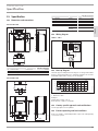
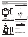
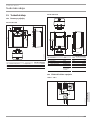
14.6 Temperaturfühler im Schutzrohr positionieren
ESH 10 U-N Trend
Führen Sie beim Austausch des Temperaturreglers den Tem-
peraturfühler in das Schutzrohr.
26�02�06�0219
185
Fixieren Sie den Temperaturfühler unter dem Erdungsstecker.
ESH 10 O-N Trend
Führen Sie beim Austausch des Temperaturreglers und des
Sicherheitstemperaturbegrenzers die Temperaturfühler in
das Schutzrohr.
L2
L1
D0000047948
L1 Temperaturregler
L2 Sicherheitstemperaturbegrenzer
L1 L2
ESH 10 O-N Trend 260 130
15. Technische Daten
15.1 Maße und Anschlüsse
ESH 10 U-N Trend
c06
c01
i13
506
22
140
366
70
276
296
100
200
D0000018561
ESH 10 U-N Trend
c01 Kaltwasser Zulauf Außengewinde G 3/8 A
c06 Warmwasser Auslauf Außengewinde G 3/8 A
i13 Wandaufhängung

INSTALLATION
Technische Daten
10 | ESH 10 U-N Trend | ESH 10 O-N Trend www.stiebel-eltron.com
ESH 10 O-N Trend
c01
i13
c06
70
a30
a20
100
22
a10
D0000018566
ESH 10 O-N Trend
a10 Gerät Höhe mm 506
a20 Gerät Breite mm 296
a30 Gerät Tiefe mm 276
c01 Kaltwasser Zulauf Außengewinde G 1/2 A
c06 Warmwasser Auslauf Außengewinde G 1/2 A
i13 Wandaufhängung
Höhe mm 386
Lochabstand
horizontal
mm 200
15.2 Elektroschaltplan
1/N/PE ~ 230V
LN
85�02�06�0001
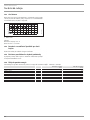
15.3 Aufheizdiagramm
Die Aufheizdauer ist abhängig von der Verkalkung und der Rest-
wärme. Die Aufheizzeit bei einem Kaltwasserzulauf mit 10°C und
maximaler Temperatureinstellung entnehmen Sie dem Diagramm.
35 40 45 50 55 60 65 70 75 80 85
0
5
10
15
20
25
D0000047118
x Temperatur in °C
y Dauer in min
Beispiel:
Temperatureinstellung = 65°C
Aufheizzeit = ca. 18min
15.4 Landesspezifische Zulassungen und Zeugnisse
Die Prüfzeichen sind auf dem Typenschild ersichtlich.
15.5 Extreme Betriebs- und Störfallbedingungen
Im Störfall kann in der Installation kurzzeitig eine Temperatur von
maximal 100 °C auftreten.
15.6 Angaben zum Energieverbrauch
Produktdatenblatt: Konventionelle Warmwasserbereiter nach
Verordnung (EU) Nr. 812/2013 und 814/2013
ESH 10 U-N
Trend
ESH 10 O-N
Trend
201391 201393
Hersteller STIEBEL ELTRON STIEBEL ELTRON
Lastprofil XXS XXS
Energieeffizienzklasse A A
Energetischer Wirkungsgrad % 37 38
Jährlicher Stromverbrauch kWh 500 491
Temperatureinstellung ab
Werk
°C 55 55
Schallleistungspegel dB(A) 15 15
Täglicher Stromverbrauch kWh 2,330 2,280

INSTALLATION
Technische Daten
DEUTSCH
www.stiebel-eltron.com ESH 10 U-N Trend | ESH 10 O-N Trend | 11
15.7 Datentabelle
ESH 10 U-N Trend ESH 10 O-N Trend
201391 201393
Hydraulische Daten
Nenninhalt l 10 10
Mischwassermenge 40 °C l 19 19
Elektrische Daten
Nennspannung V 230 230
Nennleistung kW 2 2
Nennstrom A 8,7 8,7
Absicherung A 10 10
Phasen 1/N/PE 1/N/PE
Frequenz Hz 50/60 50/60
Einsatzgrenzen
Temperatureinstellbereich °C 35-85 35-85
Max. zulässiger Druck MPa 0 0
Max. Durchflussmenge l/min 10 10
Energetische Daten
Bereitschaftsenergieverbrauch/ 24 h bei 65 °C kWh 0,32 0,31
Energieeffizienzklasse A A
Ausführungen
Schutzart (IP) IP24 D IP24 D
Montageart Untertisch X
Montageart Übertisch X
Bauart offen offen
Innenbehälter Werkstoff PP PP
Werkstoff Wärmedämmung EPS EPS
Gehäusematerial PS PS
Farbe weiß weiß
Anschlüsse
Wasseranschluss G 3/8 A G 1/2 A
Dimensionen
Höhe mm 506 506
Breite mm 296 296
Tiefe mm 276 276
Gewichte
Gewicht kg 5 5
GARANTIE | UMWELT UND RECYCLING
Garantie
Für außerhalb Deutschlands erworbene Geräte gelten nicht
die Garantiebedingungen unserer deutschen Gesellschaften.
Vielmehr kann in Ländern, in denen eine unserer Tochterge-
sellschaften unsere Produkte vertreibt, eine Garantie nur von
dieser Tochtergesellschaft erteilt werden. Eine solche Garantie
ist nur dann erteilt, wenn die Tochtergesellschaft eigene Ga-
rantiebedingungen herausgegeben hat. Darüber hinaus wird
keine Garantie erteilt.
Für Geräte, die in Ländern erworben werden, in denen keine
unserer Tochtergesellschaften unsere Produkte vertreibt, er-
teilen wir keine Garantie. Etwaige vom Importeur zugesicherte
Garantien bleiben hiervon unberührt.
Umwelt und Recycling
Bitte helfen Sie, unsere Umwelt zu schützen. Entsorgen Sie die
Materialien nach der Nutzung gemäß nationalen Vorschriften.

12 | ESH 10 U-N Trend | ESH 10 O-N Trend www.stiebel-eltron.com
CONTENTS | SPECIAL INFORMATION
SPECIAL INFORMATION
- The appliance may be used by children over 8
years of age and persons with reduced physi-
cal, sensory or mental capabilities or a lack of
experience and expertise, provided that they
are supervised or they have been instructed
on how to use the appliance safely and have
understood the potential risks. Children must
never play with the appliance. Children must
never clean the appliance or perform user
maintenance unless they are supervised.
- When permanently connected to the power
supply using a dedicated junction box, the ap-
pliance must be able to be isolated from the
mains power supply by an isolator that dis-
connects all poles with at least 3mm contact
separation.
- The power cable may only be replaced (for
example if damaged) by a qualified contrac-
tor authorised by the manufacturer, using an
original spare part.
- Never connect the appliance via a time switch.
- Secure the appliance as described in chapter
"Installation/ Installation".
- During heating, expansion water drips from
the tap outlet.
- The appliance must only be installed with an
open (non-pressurised) tap.
- Never subject the appliance to water pressure.
- The tap outlet has a vent function. Scale
build-up can block the outlet and subject the
appliance to pressure.
- Never seal the tap outlet.
- Only use special aerators for non-pressurised
water heaters.
- Never extend the tap outlet with a hose.
- Drain the appliance as described in chapter
"Installation/ Maintenance/ Draining the
appliance".
SPECIAL INFORMATION
OPERATION
1. General information ��������������������������������������� 13
1.1 Safety instructions ����������������������������������������������13
1.2 Other symbols in this documentation ����������������������13
1.3 Units of measurement �����������������������������������������13
2. Safety �������������������������������������������������������� 13
2.1 Intended use �����������������������������������������������������13
2.2 General safety instructions ����������������������������������� 13
2.3 Test symbols ����������������������������������������������������� 14
3. Appliance description ������������������������������������� 14
3.1 Operation ��������������������������������������������������������� 14
4. Cleaning, care and maintenance ������������������������� 14
5. Troubleshooting �������������������������������������������� 14
INSTALLATION
6. Safety �������������������������������������������������������� 15
6.1 General safety instructions �����������������������������������15
6.2 Instructions, standards and regulations �������������������15
7. Appliance description ������������������������������������� 15
7.1 Standard delivery ����������������������������������������������� 15
7.2 Accessories ������������������������������������������������������� 15
8. Preparation ������������������������������������������������� 15
8.1 Installation site �������������������������������������������������� 15
9. Installation �������������������������������������������������� 16
9.1 Appliance installation ������������������������������������������16
9.2 Water connection �����������������������������������������������16
9.3 Electrical connection ������������������������������������������� 17
10. Commissioning ��������������������������������������������� 17
10.1 Initial start-up ��������������������������������������������������� 17
10.2 Recommissioning ����������������������������������������������� 17
11. Settings ����������������������������������������������������� 17
11.1 Setting the temperature limit �������������������������������� 17
12. Appliance shutdown ��������������������������������������� 17
13. Troubleshooting �������������������������������������������� 17
14. Maintenance ������������������������������������������������ 18
14.1 Draining the appliance ���������������������������������������� 18
14.2 Opening the appliance ����������������������������������������� 18
14.3 Descaling the appliance ���������������������������������������18
14.4 Replacing the power cable �����������������������������������18
14.5 Checking the earth conductor ��������������������������������18
14.6 Positioning the temperature sensor in its protective
pipe ���������������������������������������������������������������� 18
15. Specification ������������������������������������������������ 19
15.1 Dimensions and connections ��������������������������������� 19
15.2 Wiring diagram ������������������������������������������������� 19
15.3 Heat-up diagram ������������������������������������������������ 19
15.4 Country-specific approvals and certifications ������������� 19
15.5 Extreme operating and fault conditions ������������������� 19
15.6 Energy consumption data �������������������������������������20
15.7 Data table �������������������������������������������������������� 20
GUARANTEE | ENVIRONMENT AND RECYCLING
OPERATION AND INSTALLATION
Open vented (non-pressurised) small water heater

OPERATION
General information
www.stiebel-eltron.com ESH 10 U-N Trend | ESH 10 O-N Trend | 13
ENGLISH
OPERATION
1. General information
The chapters "Special information" and "Operation" are intended
for both users and qualified contractors.
The chapter "Installation" is intended for qualified contractors.
Note
Read these instructions carefully before using the appli-
ance and retain them for future reference.
Pass on the instructions to a new user if required.
1.1 Safety instructions
1.1.1 Structure of safety instructions
!
KEYWORD Type of risk
Here, possible consequences are listed that may result
from failure to observe the safety instructions.
Steps to prevent the risk are listed.
1.1.2 Symbols, type of risk
Symbol Type of risk
Injury
Electrocution
Burns
(burns, scalding)
1.1.3 Keywords
KEYWORD Meaning
DANGER Failure to observe this information will result in serious
injury or death.
WARNING Failure to observe this information may result in serious
injury or death.
CAUTION Failure to observe this information may result in non-seri-
ous or minor injury.
1.2 Other symbols in this documentation
Note
General information is identified by the adjacent symbol.
Read these texts carefully.
Symbol Meaning
Material losses
(appliance damage, consequential losses and environmen-
tal pollution)
Appliance disposal
This symbol indicates that you have to do something. The ac-
tion you need to take is described step by step.
1.3 Units of measurement
Note
All measurements are given in mm unless stated oth-
erwise.
2. Safety
2.1 Intended use
This open vented (non-pressurised) appliance is designed for heat-
ing domestic hot water. The appliance can supply one draw-off
point.
The appliance is intended for domestic use. It can be used safely
by untrained persons. The appliance can also be used in non-do-
mestic environments, e.g. in small businesses, as long as it is
used in the same way.
Any other use beyond that described shall be deemed inappro-
priate. Observation of these instructions and of the instructions
for any accessories used is also part of the correct use of this
appliance.
2.2 General safety instructions
WARNING Burns
During operation, the tap can reach temperatures in ex-
cess of 60°C.
There is a risk of scalding at outlet temperatures in ex-
cess of 43°C.
!
WARNING Injury
Only a qualified contractor is permitted to remove the
temperature selector.
!
WARNING Injury
The appliance may be used by children over 8 years of
age and persons with reduced physical, sensory or men-
tal capabilities or a lack of experience and expertise,
provided that they are supervised or they have been
instructed on how to use the appliance safely and have
understood the potential risks. Children must never play
with the appliance. Children must never clean the ap-
pliance or perform user maintenance unless they are
supervised.
Where children or persons with limited physical, sensory or men-
tal abilities are allowed to use this appliance, we recommend a
permanent temperature limit. A qualified contractor can set this
limit.
!
!

OPERATION
Appliance description
14 | ESH 10 U-N Trend | ESH 10 O-N Trend www.stiebel-eltron.com
!
Material losses
The user should protect the appliance and its tap against
frost.
!
Material losses
Never subject the appliance to water pressure. The tap
outlet has a vent function. Scale build-up can block the
outlet and subject the appliance to pressure.
Never seal the tap outlet.
Only use special aerators for non-pressurised water
heaters.
Never extend the tap outlet with a hose.
!
Material losses
Connecting the appliance via a time switch will cause an
unintentional reset of the high limit safety cut-out.
Never connect the appliance to the power supply via
a time switch.
2.3 Test symbols
See type plate on the appliance.
3. Appliance description
This open vented (non-pressurised) appliance constantly main-
tains the water content at the pre-selected temperature. During
heating, expansion water drips from the tap. The appliance may
only be installed with taps for open vented (non-pressurised)
water heaters (see chapter "Installation/ Appliance description/
Accessories").
Subject to season, varying cold water temperatures can result in
different maximum amounts of mixed outlet water.
Thermostop function
The thermostop function (thermal separation) of the
ESH10U-NTrend prevents the tap becoming hot in standby mode.
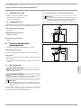
3.1 Operation
You can set any required DHW outlet temperature variably at the
temperature selector. The heat-up indicator illuminates during
the heat-up process.
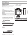
26�02�06�0154
ESH 10 U-N Trend
ESH 10 O-N Trend
1
2
2
1
1 Heat-up indicator
2 Temperature selector
Depending on the system, the actual temperatures may vary from
the set value.
• Cold. On this setting, the appliance is protected from frost.
The tap and the water line are not protected.
E Approx. 40°C
e Recommended energy saving setting (approx. 60°C),
minor scaling
Note
A qualified contractor can set a temperature limit on the
appliance (see chapter "Installation/ Settings/ Setting
the temperature limit").
4. Cleaning, care and maintenance
Never use abrasive or corrosive cleaning agents. A damp
cloth is sufficient for cleaning the appliance.
Check the tap regularly. You can remove limescale depos-
its at the tap outlet using commercially available descaling
agents.
Almost every type of water will deposit limescale at high temper-
atures. This settles inside the appliance and affects both perfor-
mance and service life. The heating elements should therefore be
descaled if necessary. A qualified contractor who is aware of the
local water quality will tell you when the next descaling is due.
5. Troubleshooting
Problem Cause Remedy
The appliance does not
supply hot water.
The temperature selector
is set to “
•”.
Switch the appliance ON
by turning the tempera-
ture selector.
No power at the appli-
ance.
Check the plug/ fuses in
the distribution board.
Water can only be drawn
at a reduced rate.
The aerator in the tap is
scaled up.
Descale/ replace the
aerator.
Loud boiling noises in-
side the appliance.
The appliance is scaled
up.
Have the appliance
descaled by a qualified
contractor.
If you cannot remedy the fault, contact your qualified contractor.
To facilitate and speed up your enquiry, please provide the serial
number from the type plate (000000-0000-000000).

INSTALLATION
Safety
www.stiebel-eltron.com ESH 10 U-N Trend | ESH 10 O-N Trend | 15
ENGLISH
INSTALLATION
6. Safety
Only a qualified contractor should carry out installation, commis-
sioning, maintenance and repair of the appliance.
6.1 General safety instructions
We guarantee trouble-free function and operational reliability only
if original accessories and spare parts intended for the appliance
are used.
6.2 Instructions, standards and regulations
Note
Observe all applicable national and regional regulations
and instructions.
7. Appliance description
The appliance is intended to heat cold water for supplying a single
draw-off point.
ESH 10 U-N Trend
The open vented (non-pressurised) appliance is only suitable for
undersink installation.
ESH 10 O-N Trend
The open vented (non-pressurised) appliance is suitable only for
oversink installation.
7.1 Standard delivery
The following are delivered with the appliance:
- Wall mounting bracket
- Installation template
7.2 Accessories
The following taps are available as accessories for open vented
operation:
Mixer taps
- WST, WUT
Mono-lever mixer taps
- MEW, MES, MEWC
Sensor tap
- WEN
8. Preparation
Flush the water line thoroughly.
Water installation
No safety valve is required.
Taps
Sealed unvented taps are not permitted.
Install a tap for open vented operation.
8.1 Installation site
!
Material losses
Install the appliance in a room free from the risk of frost.
!
Material losses
Mount the appliance on the wall. The wall must have
sufficient load bearing capacity.
Note
Ensure that the appliance is freely accessible for main-
tenance work.
Always install the appliance vertically and near the draw-off point.
8.1.1 ESH 10 U-N Trend - undersink installation
Note
The ESH 10 U-N Trend is designed exclusively for under-
sink installation. The water connections of the appliance
are at the top.
820
520-570
D0000047854
850
550-600
D0000047858

INSTALLATION
Installation
16 | ESH 10 U-N Trend | ESH 10 O-N Trend www.stiebel-eltron.com
8.1.2 ESH 10 O-N Trend - oversink installation
Note
The ESH 10 O-N Trend is designed exclusively for oversink
installation. The water connections of the appliance point
downwards.
850 200-300
300
D0000047855
!
Material losses
Connecting hose length (from tap to appliance) may not
exceed 1m.
For connecting hoses >1m:
Install a tube aerator attachment in the overflow
line.
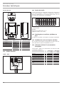
9. Installation
9.1 Appliance installation
Mark out the holes for drilling with the installation template
supplied.
Drill the holes and insert suitable rawl plugs.
Secure the wall mounting bracket using suitable screws.
Hang the appliance on the wall mounting bracket.
Note
Surplus cable can be stored in the cable compartment.
26�02�06�0163
9.2 Water connection
!
Material losses
Carry out all water connection and installation work in
accordance with regulations.
!
Material losses
The appliance may develop a leak and cease functioning.
Never subject the appliance to water pressure.
Never interchange the water connections.
Set the flow rate (see tap instructions). Observe the
maximum permissible flow rate with a fully opened
tap (see chapter "Installation/ Specification/ Data
table").
!
Material losses
When tightening the fittings, counterhold with a suitable
spanner.
ESH 10 U-N Trend
D0000047852
Match up the colour coding on the tap water connections and the
appliance:
- R.h. side blue = "Cold water inlet"
- L.h. side red = "DHW outlet"
Secure the water connections from the tap to the appliance.
Note
Ensure that the water connections are not kinked during
installation. Prevent any tensioning during installation.
ESH 10 O-N Trend
D0000047853
Secure the water connections from the tap to the appliance.

INSTALLATION
Commissioning
www.stiebel-eltron.com ESH 10 U-N Trend | ESH 10 O-N Trend | 17
ENGLISH
9.3 Electrical connection
WARNING Electrocution
Carry out all electrical connection and installation work
in accordance with relevant regulations.
WARNING Electrocution
When permanently connected to the power supply using
a dedicated junction box, the appliance must be able to
be isolated from the mains power supply by an isolator
that disconnects all poles with at least 3mm contact
separation.
WARNING Electrocution
Ensure that the appliance is earthed.
!
Material losses
The voltage specified on the type plate must match the
mains voltage.
Observe the type plate.
The following electrical connections are permissible:
ESH 10 U-N
Trend
ESH 10 O-N
Trend
Connection to a freely accessible standard
socket with matching plug
X X
Permanent connection to an appliance junc-
tion box with earth conductor
X X
10. Commissioning
WARNING Electrocution
Commissioning may only be carried out by a qualified
contractor in accordance with safety regulations.
10.1 Initial start-up
1. 2.
D0000049325
Either open the DHW valve of the tap or set the mono lever
mixer tap to "hot" until the water that flows out is free of air
bubbles.
Insert the plug into the standard socket or set the fuse/MCB
in the distribution board.
Select a temperature.
Check the entire hydraulic installation for tightness.
Note
If you fail to follow the correct sequence (first water, then
power), the high limit safety cut-out will trip.
Proceed as follows:
Disconnect the appliance from the power supply.
Fill the appliance with water.
Connect the appliance to the power supply.
10.1.1 Appliance handover
Explain the functions of the appliance to the user. Show the
user how to operate the appliance.
Make the user aware of potential dangers, especially the risk
of scalding.
Hand over these instructions and, if applicable, the instruc-
tions for any accessories.
10.2 Recommissioning
See chapter "Installation/ Commissioning/ Initial start-up".
11. Settings
11.1 Setting the temperature limit
26�02�06�0152
The lever underneath the temperature selector allows you to limit
the setting range of the temperature selector to a specific maxi-
mum temperature.
Turn the temperature selector to zero (fully anti-clockwise to
"•").
Pull off the temperature selector.
Adjust the lever to the required maximum temperature.
Install the temperature selector set to zero (•
).
12. Appliance shutdown
Isolate the appliance from the power supply by removing the
plug or by tripping the MCB in the distribution board.
Drain the appliance (see chapter "Installation/ Maintenance/
Draining the appliance").
13. Troubleshooting
Fault Cause Remedy
The appliance
does not supply
hot water.
The appliance was not filled
with water before being
connected to the power
supply. The correct com-
missioning sequence was
not observed. The high limit
safety cut-out has tripped.
Pull the plug from the power
socket. Fill the appliance with
water. Re-insert the plug into
the standard socket (see chap-
ter “Installation/ Commission-
ing”).
The high limit safety cut-out
has tripped.
Remedy the cause of the fault.
If necessary, replace the tem-
perature controller. Allow the
appliance to cool down. If you
have isolated the appliance
from the power supply, the high
limit safety cut-out will be reset
automatically.
Loud boiling
noises inside
the appliance.
The appliance is scaled up.
Descale the appliance.

INSTALLATION
Maintenance
18 | ESH 10 U-N Trend | ESH 10 O-N Trend www.stiebel-eltron.com
14. Maintenance
WARNING Electrocution
Before any work on the appliance, disconnect all poles
of the appliance from the power supply.
Dismantle the appliance for maintenance work.
14.1 Draining the appliance
WARNING Burns
Hot water may escape during draining.
Drain the appliance via its connectors.
14.2 Opening the appliance
26�02�06�0153
Pull off the temperature selector.
Remove the screws from underneath the temperature
selector.
Open the appliance cover by lowering the bolt screws in-
wards and pivot the cover upwards, then remove it.
14.3 Descaling the appliance
!
Material losses
Never treat the cylinder surface with descaling agents.
Remove the flanged immersion heater.
Carefully tap the heating element to remove coarse limescale
deposits.
Immerse the heating element up to the flange plate in desca-
ling agent.
14.4 Replacing the power cable
The power cable must only be replaced by a qualified contractor
with an original spare part. Alternatively, the H05VV-F3x1.0 cable
may be used.
Note
Never remove the plastic thread holding the profile plate.
14.5 Checking the earth conductor
Pull off the temperature selector.
Check the earth conductor (in Germany DGUVV3 for exam-
ple) across a temperature controller fixing screw and the
earth conductor contact of the power cable.
14.6 Positioning the temperature sensor in its
protective pipe
ESH 10 U-N Trend
When replacing the temperature controller, guide the tem-
perature sensor into its protective pipe.
26�02�06�0219
185
Secure the temperature sensor in place below the earthed
plug.
ESH 10 O-N Trend
When replacing the temperature controller and the high limit
safety cut-out, guide the temperature sensors into the pro-
tective pipe.
L2
L1
D0000047948
L1 Temperature controller
L2 High limit safety cut-out
L1 L2
ESH 10 O-N Trend 260 130

INSTALLATION
www.stiebel-eltron.com ESH 10 U-N Trend | ESH 10 O-N Trend | 19
ENGLISH
15. Specification
15.1 Dimensions and connections
ESH 10 U-N Trend
c06
c01
i13
506
22
140
366
70
276
296
100
200
D0000018561
ESH 10 U-N Trend
c01 Cold water inlet Male thread G 3/8 A
c06 DHW outlet Male thread G 3/8 A
i13 Wall mounting bracket
ESH 10 O-N Trend
c01
i13
c06
70
a30
a20
100
22
a10
D0000018566
ESH 10 O-N Trend
a10 Appliance Height mm 506
a20 Appliance Width mm 296
a30 Appliance Depth mm 276
c01 Cold water inlet Male thread G 1/2 A
c06 DHW outlet Male thread G 1/2 A
i13 Wall mounting bracket
Height mm 386
Horizontal hole
spacing
mm 200
15.2 Wiring diagram
1/N/PE ~ 230V
LN
85�02�06�0001
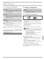
15.3 Heat-up diagram
The heat-up period depends on the degree of scaling and residual
heat. For the heat-up time for a cold water supply at 10 °C and a
maximum temperature setting, see the diagram.
35 40 45 50 55 60 65 70 75 80 85
0
5
10
15
20
25
D0000047118
x Temperature in °C
y Duration in min
Example:
Temperature setting = 65°C
Heat-up time = approx. 18minutes
15.4 Country-specific approvals and certifications
See the type plate for test symbols.
15.5 Extreme operating and fault conditions
In the case of faults, a peak temperature of up to 100 °C may briefly
occur in the system.

INSTALLATION
20 | ESH 10 U-N Trend | ESH 10 O-N Trend www.stiebel-eltron.com
15.6 Energy consumption data
Product datasheet: Conventional water heaters to regulation (EU) no. 812/2013 and 814/2013
ESH 10 U-N Trend ESH 10 O-N Trend
201391 201393
Manufacturer STIEBEL ELTRON STIEBEL ELTRON
Load profile XXS XXS
Energy efficiency class A A
Energy conversion efficiency % 37 38
Annual power consumption kWh 500 491
Default temperature setting °C 55 55
Sound power level dB(A) 15 15
Daily power consumption kWh 2.330 2.280
15.7 Data table
ESH 10 U-N Trend ESH 10 O-N Trend
201391 201393
Hydraulic data
Nominal capacity l 10 10
Mixed water volume at 40 °C l 19 19
Electrical data
Rated voltage V 230 230
Rated output kW 2 2
Rated current A 8.7 8.7
Fuse protection A 10 10
Phases 1/N/PE 1/N/PE
Frequency Hz 50/60 50/60
Application limits
Temperature setting range °C 35-85 35-85
Max. permissible pressure MPa 0 0
Max. flow rate l/min 10 10
Energy data
Standby energy consumption/24 h at 65°C kWh 0.32 0.31
Energy efficiency class A A
Versions
IP rating IP 24 D IP 24 D
Undersink installation X
Oversink installation X
Type Open vented Open vented
Inner cylinder material PP PP
Thermal insulation material EPS EPS
Casing material PS PS
Colour White White
Connections
Water connection G 3/8 A G 1/2 A
Dimensions
Height mm 506 506
Width mm 296 296
Depth mm 276 276
Weights
Weight kg 5 5
La page est en cours de chargement...
La page est en cours de chargement...
La page est en cours de chargement...
La page est en cours de chargement...
La page est en cours de chargement...
La page est en cours de chargement...
La page est en cours de chargement...
La page est en cours de chargement...
La page est en cours de chargement...
La page est en cours de chargement...
La page est en cours de chargement...
La page est en cours de chargement...
La page est en cours de chargement...
La page est en cours de chargement...
La page est en cours de chargement...
La page est en cours de chargement...
La page est en cours de chargement...
La page est en cours de chargement...
La page est en cours de chargement...
La page est en cours de chargement...
La page est en cours de chargement...
La page est en cours de chargement...
La page est en cours de chargement...
La page est en cours de chargement...
La page est en cours de chargement...
La page est en cours de chargement...
La page est en cours de chargement...
La page est en cours de chargement...
La page est en cours de chargement...
La page est en cours de chargement...
La page est en cours de chargement...
La page est en cours de chargement...
La page est en cours de chargement...
La page est en cours de chargement...
La page est en cours de chargement...
La page est en cours de chargement...
La page est en cours de chargement...
La page est en cours de chargement...
La page est en cours de chargement...
La page est en cours de chargement...
La page est en cours de chargement...
La page est en cours de chargement...
La page est en cours de chargement...
La page est en cours de chargement...
La page est en cours de chargement...
La page est en cours de chargement...
La page est en cours de chargement...
La page est en cours de chargement...
La page est en cours de chargement...
La page est en cours de chargement...
La page est en cours de chargement...
La page est en cours de chargement...
La page est en cours de chargement...
La page est en cours de chargement...
La page est en cours de chargement...
La page est en cours de chargement...
La page est en cours de chargement...
La page est en cours de chargement...
La page est en cours de chargement...
La page est en cours de chargement...
La page est en cours de chargement...
La page est en cours de chargement...
La page est en cours de chargement...
La page est en cours de chargement...
La page est en cours de chargement...
La page est en cours de chargement...
La page est en cours de chargement...
La page est en cours de chargement...
La page est en cours de chargement...
La page est en cours de chargement...
La page est en cours de chargement...
La page est en cours de chargement...
La page est en cours de chargement...
La page est en cours de chargement...
La page est en cours de chargement...
La page est en cours de chargement...
-
 1
1
-
 2
2
-
 3
3
-
 4
4
-
 5
5
-
 6
6
-
 7
7
-
 8
8
-
 9
9
-
 10
10
-
 11
11
-
 12
12
-
 13
13
-
 14
14
-
 15
15
-
 16
16
-
 17
17
-
 18
18
-
 19
19
-
 20
20
-
 21
21
-
 22
22
-
 23
23
-
 24
24
-
 25
25
-
 26
26
-
 27
27
-
 28
28
-
 29
29
-
 30
30
-
 31
31
-
 32
32
-
 33
33
-
 34
34
-
 35
35
-
 36
36
-
 37
37
-
 38
38
-
 39
39
-
 40
40
-
 41
41
-
 42
42
-
 43
43
-
 44
44
-
 45
45
-
 46
46
-
 47
47
-
 48
48
-
 49
49
-
 50
50
-
 51
51
-
 52
52
-
 53
53
-
 54
54
-
 55
55
-
 56
56
-
 57
57
-
 58
58
-
 59
59
-
 60
60
-
 61
61
-
 62
62
-
 63
63
-
 64
64
-
 65
65
-
 66
66
-
 67
67
-
 68
68
-
 69
69
-
 70
70
-
 71
71
-
 72
72
-
 73
73
-
 74
74
-
 75
75
-
 76
76
-
 77
77
-
 78
78
-
 79
79
-
 80
80
-
 81
81
-
 82
82
-
 83
83
-
 84
84
-
 85
85
-
 86
86
-
 87
87
-
 88
88
-
 89
89
-
 90
90
-
 91
91
-
 92
92
-
 93
93
-
 94
94
-
 95
95
-
 96
96


STIEBEL ELTRON ESH 10 O-N Trend +A Operation Instruction
- Taper
- Operation Instruction
- Ce manuel convient également à
dans d''autres langues
- Deutsch: STIEBEL ELTRON ESH 10 O-N Trend +A
- slovenčina: STIEBEL ELTRON ESH 10 O-N Trend +A
- polski: STIEBEL ELTRON ESH 10 O-N Trend +A
Documents connexes
-
STIEBEL ELTRON ESH 5_U-N_O-N-Trend Operation Instruction
-
STIEBEL ELTRON ESH 10 U-P Plus Guide d'installation
-
-
STIEBEL ELTRON UFP 5 h Operation Instruction
-
-
-
-
-
-
STIEBEL ELTRON WST fitting for small pressure less tanks Guide d'installation

