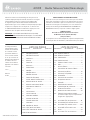
Sauder Corner Entertainment Credenza 403818 Mode d'emploi
- Taper
- Mode d'emploi

NOTE: THIS INSTRUCTION
BOOKLET CONTAINS IMPORTANT
SAFETY INFORMATION.
PLEASE READ AND KEEP FOR
FUTURE REFERENCE.
English pg 1-28
Français pg 29-32
Español pg 33-36
Lot # 375372 07/06/15
Purchased: __________________
Be sure to give us a ring before
making any returns. 1-800-523-3987
Corner Entertainment Credenza
Orchard Hills Collection | 403818
Need help? Visit Sauder.com to view video assembly tips or chat with a live rep.
Prefer the phone? Call 1-800-523-3987.
Share your journey!
sauder.com
Smart stand
for the idiot box.

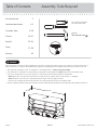
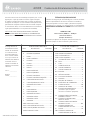
Table of Contents Assembly Tools Required
3
4-5
6-28
29-32
33-36
37-38
39
Part Identifi cation
Hardware Identifi cation
Assembly Steps
Français
Español
Safety
Warranty
Hammer
Not actual size
No. 2 Phillips Screwdriver
Tip Shown Actual Size
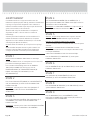
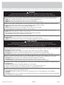
Use of a TV that is too heavy or large is hazardous. A TV that is too heavy will create a risk of a tip-over that can cause severe injury or
death. A TV that is too large for the available space might be accidentally pushed or bumped o the furniture, or subject to tip-over.
• Check the size and weight of your TV. Compare it to the diagram below – before you begin assembly!
• This Sauder unit is designed for use with televisions weighing less than 135 pounds. Never use with a TV that weighs more.
• The size of the television, front-to-back and side-to-side, must fi t within the space defi ned in the diagram.
• Never place the front edge of the TV past the front edge of the TV support shelf (or stop molding – if equipped)
• Never allow the sides of the TV to extend past the side edges of the TV support surface.
• If the TV has a CRT picture tube, the picture tube cone may extend past the rear of the support shelf.
• Be sure to apply the warning label as instructed in the last assembly step. The label provides important safety related information.
WARNING
!
135 lbs.
135 lbs.
18-7/8"
18-7/8"
60-1/8"
60-1/8"
403818 www.sauder.com/servicesPage 2

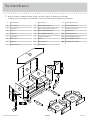
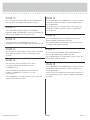
Part Identifi cation
å While not all parts are labeled, some of the parts will have a label or an inked letter on the edge
to help distinguish similar parts from each other. Use this part identifi cation to help identify similar parts.
A RIGHT END (1)
B LEFT END (1)
C UPRIGHT (1)
D TOP (1)
E SHELF (2)
F BOTTOM (1)
G BRACE (2)
H BACK (1)
I RIGHT BACK (1)
J LEFT BACK (1)
K ADJUSTABLE SHELF (2)
L SMALL ADJUSTABLE SHELF (2)
M RIGHT DRAWER FRONT (1)
N LEFT DRAWER FRONT (1)
S SHELF MOLDING (1)
T BASE (1)
U RIGHT BASE (1)
V LEFT BASE (1)
W BACK MOLDING (2)
X LONG MOLDING (2)
Y SHORT MOLDING (2)
Z MOLDING (4)
D65 DRAWER BACK (2)
D107 RIGHT DRAWER SIDE (2)
D108 LEFT DRAWER SIDE (2)
D962 DRAWER BOTTOM (2)
403818www.sauder.com/services
Page 3
M
N
D107D65
D962
D108
D107
D65
D962
D108
A
B
C
D
E
F
G
H
I
J
K
L
S
T
U
V
W
X
Y
Z
X
Z
Z
Z
G
K
E
L
W
Y

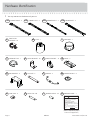
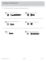
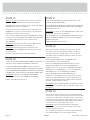
Hardware Identifi cation
å You may receive extra hardware with your unit.
403818 www.sauder.com/servicesPage 4
35DA
CABINET RIGHT - 2
35DB
CABINET LEFT - 2
35DC
DRAWER RIGHT - 2
35DD
DRAWER LEFT - 2
FF
TWIST-LOCK
®
FASTENER - 18
FOOT - 1
GG
GROMMET - 1
II
GROMMET CAP- 1
JJ
METAL BRACKET - 18
KK
ANGLE BRACKET - 12
LL
HINGE - 2
MM
RAIL BRACKET - 4
NN
HANDLE - 2
PP
HANDLE MOUNT - 4
QQ
RR
SLIDE CAM - 4 METAL PIN - 20
SS
RUBBER SLEEVE - 16
TT
UU
WARNING LABEL - 1
WARNING
Never use this furniture with a TV that is too
large or too heavy. Severe injury or death
can occur. The TV and furniture will be
unstable and may tip.
-The TV must less than 135 lbs.
-The base of the TV must be able to sit
completely on this shelf.
-Refer to instruction book for complete safety
information.
Note: This is a permanent label. Do not try
to remove. Surface will be damaged.
02/ 02 2 6 9 2 3 2 269232
(Refer to Step 22 for proper
location and application)
TIE PLATE -2
OO

Hardware Identifi cation
å Screws are shown actual size. You may receive extra hardware with your unit.
403818www.sauder.com/services
Page 5
BLACK 1-7/8" FLAT HEAD SCREW - 10
VV
BLACK 9/16" LARGE HEAD SCREW - 98
XX YY
GOLD 5/16" FLAT HEAD SCREW - 16
NAIL - 24
ZZ 30S
BLACK 1-9/16" FLAT HEAD SCREW - 8
15S
SILVER 5/8" MACHINE SCREW - 4

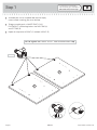
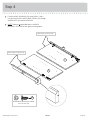
Step 1
Look for this icon. It means a
video assembly tip is available at
www.sauder.com/services/tips
å
Assemble your unit on a carpeted fl oor or on the empty
carton to avoid scratching your unit or the fl oor.
å
To begin assembly, push a SAUDER TWIST-LOCK®
FASTENER (FF) into the large holes in the RIGHT END (A)
and LEFT END (B).
å
Repeat this step for the UPRIGHT (C) and both SHELVES (E).
403818 www.sauder.com/servicesPage 6
(18 used)
FF
Do not tighten the TWIST-LOCK® FASTENERS in this step.
A
B

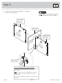
å
Fasten twelve ANGLE BRACKETS (LL) to the
ENDS (A and B) and BOTTOM (F). Use twelve
BLACK 9/16" LARGE HEAD SCREWS (XX).
å
NOTE: Be sure the edges of the ANGLE BRACKETS
are even with the edges of the ENDS and BOTTOM.
Step 2
403818www.sauder.com/services
Page 7
BLACK 9/16" LARGE HEAD SCREW
(12 used in this step)
XX
(12 used)
LL
LL
A
B
F
Surface with
TWIST-LOCK®
FASTENERS
Surface with
TWIST-LOCK®
FASTENERS
Unfi nished surface

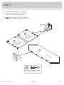
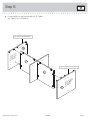
Step 3
å
Fasten twelve METAL BRACKETS (KK) to the BOTTOM (F)
and BACKS (I and J). Use twelve BLACK 9/16" LARGE
HEAD SCREWS (XX).
å
NOTE: Be sure the edges of the METAL BRACKETS are even
with the edges of the BOTTOM and BACKS.
403818 www.sauder.com/servicesPage 8
I
J
F
Finished
surface
Finished
surface
BLACK 9/16" LARGE HEAD SCREW
(12 used in this step)
XX
KK
KK
KK
KK
Unfi nished surface

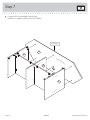
å
Fasten the BACK MOLDINGS (W) to the BACKS (I and J).
Use four BLACK 9/16" LARGE HEAD SCREWS (XX) through
the BRACKETS and into the MOLDINGS.
å
NOTE: There are no pre-drilled holes in the BACK
MOLDINGS. The SCREWS will tighten into the grooves.
Step 4
403818www.sauder.com/services
Page 9
BLACK 9/16" LARGE HEAD SCREW
(4 used in this step)
XX
I
J
W
W
These edges should be even.
These edges should be even.

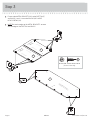
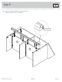
Step 5
å
Fasten the SHELVES (E) to the UPRIGHT (C). Tighten four
TWIST-LOCK® FASTENERS.
403818 www.sauder.com/servicesPage 10
C
E
Surface with
TWIST-LOCK®
FASTENERS
Surface without
TWIST-LOCK®
FASTENERS
How to use the SAUDER TWIST-LOCK
®
FASTENER
1. Insert the dowel end of the FASTENER into the hole of the
adjoining part.
NOTE: The dowel end of the FASTENER must remain fully
inserted in the hole of the adjoining part while locking
the FASTENER.
2. Tighten the FASTENER with a Phillips screwdriver as tight
as possible.
E
Surface with
TWIST-LOCK®
FASTENERS
Finished edge
Long edge with
TWIST-LOCK®
FASTENERS
Long edge with
TWIST-LOCK®
FASTENERS
Do not stand the unit upright without the
BACK fastened. The unit may collapse.
Caution
Dowel end

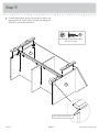
å
Fasten the ENDS (A and B) to the SHELVES (E). Tighten
four TWIST-LOCK® FASTENERS.
Step 6
403818www.sauder.com/services
Page 11
B
E
E
A
Surface with
TWIST-LOCK®
FASTENERS
Surface without
TWIST-LOCK®
FASTENERS
Edge with ANGLE BRACKETS
Edge with ANGLE BRACKETS

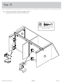
Step 7
å
Fasten the TOP (D) to the ENDS (A and B) and
UPRIGHT (C). Tighten six TWIST-LOCK® FASTENERS.
403818 www.sauder.com/servicesPage 12
Curved edge
B
D
C
A
Surface with holes

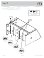
å
Fasten the SHELF MOLDING (S) to the SHELVES (E).
Tighten four TWIST-LOCK® FASTENERS.
Step 8
403818www.sauder.com/services
Page 13
E
E
S
Curved edge

Step 9
å
Fasten the MOLDINGS (X and Y) to the ENDS (A and B). Use
eight BLACK 9/16" LARGE HEAD SCREWS (XX) through the
BRACKETS and into the MOLDINGS.
403818 www.sauder.com/servicesPage 14
BLACK 9/16" LARGE HEAD SCREW
(8 used in this step)
XX
A
B
X
Y
X
Y
These edges should be even.

å
Fasten the RAIL BRACKETS (NN) to the ENDS (A and B).
Use eight BLACK 9/16" LARGE HEAD SCREWS (XX).
Step 10
403818www.sauder.com/services
Page 15
BLACK 9/16" LARGE HEAD SCREW
(8 used in this step)
XX
NN
NN
A
B

Step 11
å
Fasten the CABINET RIGHTS (35DA) and CABINET
LEFTS (35DB) to the ENDS (A and B) and UPRIGHT (C).
Use eight GOLD 5/16" FLAT HEAD SCREWS (YY).
403818 www.sauder.com/servicesPage 16
A
B
GOLD 5/16" FLAT HEAD SCREW
(8 used in this step)
YY
Roller end
Roller end
C

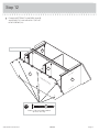
å
Fasten the BOTTOM (F) to the ENDS (A and B)
and UPRIGHT (C). Use six BLACK 1-7/8" FLAT
HEAD SCREWS (VV).
Step 12
403818www.sauder.com/services
Page 17
Edge with ANGLE BRACKETS
A
B
C
F
Unfi nished surface
BLACK 1-7/8" FLAT HEAD SCREW
(6 used in this step)
VV

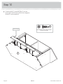
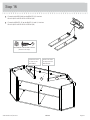
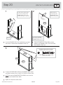
Step 13
å
Fasten the BASE (T) to the BOTTOM (F). Use four
BLACK 9/16" LARGE HEAD SCREWS (XX) through the
BRACKETS and into the BASE.
403818 www.sauder.com/servicesPage 18
F
T
BLACK 9/16" LARGE HEAD SCREW
(4 used in this step)
XX
Curved edge

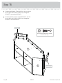
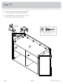
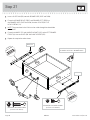
å
Carefully turn your unit onto its top.
å
Insert four METAL PINS (SS) into the BACKS (I and J).
å
Insert the METAL PINS (SS) in one end of the BACKS (I and J)
into the holes in the TOP (D).
å
Fasten the BACKS (I and J) to the BOTTOM (F). Use four
BLACK 1-7/8" FLAT HEAD SCREWS (VV).
Step 14
403818www.sauder.com/services
Page 19
BLACK 1-7/8" FLAT HEAD SCREW
(4 used in this step)
VV
F
J
I
D
SS
SS
Unfi nished surface
Unfi nished surface

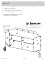
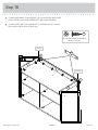
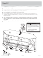
Step 15
å
Fasten the MOLDINGS (Z) to the BACKS (I and J). Use four
BLACK 9/16" LARGE HEAD SCREWS (XX) through the
BRACKETS and into the MOLDINGS.
å
Fasten the BASES (U and V) to the BOTTOM (F). Use four
BLACK 9/16" LARGE HEAD SCREWS (XX) through the
BRACKETS and into the BASES.
403818 www.sauder.com/servicesPage 20
BLACK 9/16" LARGE HEAD SCREW
(8 used in this step)
XX
F
J
I
Z
U
V
Z
Curved edge
Flat edge
La page est en cours de chargement...
La page est en cours de chargement...
La page est en cours de chargement...
La page est en cours de chargement...
La page est en cours de chargement...
La page est en cours de chargement...
La page est en cours de chargement...
La page est en cours de chargement...
La page est en cours de chargement...
La page est en cours de chargement...
La page est en cours de chargement...
La page est en cours de chargement...
La page est en cours de chargement...
La page est en cours de chargement...
La page est en cours de chargement...
La page est en cours de chargement...
La page est en cours de chargement...
La page est en cours de chargement...
La page est en cours de chargement...
La page est en cours de chargement...
-
 1
1
-
 2
2
-
 3
3
-
 4
4
-
 5
5
-
 6
6
-
 7
7
-
 8
8
-
 9
9
-
 10
10
-
 11
11
-
 12
12
-
 13
13
-
 14
14
-
 15
15
-
 16
16
-
 17
17
-
 18
18
-
 19
19
-
 20
20
-
 21
21
-
 22
22
-
 23
23
-
 24
24
-
 25
25
-
 26
26
-
 27
27
-
 28
28
-
 29
29
-
 30
30
-
 31
31
-
 32
32
-
 33
33
-
 34
34
-
 35
35
-
 36
36
-
 37
37
-
 38
38
-
 39
39
-
 40
40


Sauder Corner Entertainment Credenza 403818 Mode d'emploi
- Taper
- Mode d'emploi
dans d''autres langues
Documents connexes
-
Sauder Shoal Creek 422194 Mode d'emploi
-
-
-
-
-
-
-
-
-
