Rae EntryRAE PGM-3000 Manuel utilisateur
- Taper
- Manuel utilisateur

EntryRAE
USER MANUAL
PGM-3000
Multi-Gas Monitor
046-4001-000, Revision C, June 2005

b
Read Before Operating
This manual must be carefully read by all individuals who have
or will have the responsibility of using, maintaining, or servicing
this product. The product will perform as designed only if
it is used, maintained, and serviced in accordance with the
manufacturer’s instructions.
Caution!
To reduce the risk of electric shock, turn off power before removing the
monitor cover. Disconnect the battery before removing sensor modules for
service. Never operate this monitor while the cover is removed. Remove
monitor cover and sensor modules only in an area known to be non-
hazardous.
Special Note
When the EntryRAE monitor is removed from the transport case and is
turned on for the first time, there may be residual vapors trapped inside the
monitor, and the initial toxic gas sensors values may indicate a few ppm.
After running the monitor for several minutes in clean air, the residual vapors
should clear and readings should return to near zero.
Attention! For European Applications
A. Recharge batteries in non-hazardous locations.
B . Do not connect external cable to serial interface jack in hazardous locations.
C. Use RAE Systems Charging cradle (P/N 046-3059-000) for connection to
communication port and charging jack only in a non hazardous area.
Note
Only the combustible gas detection portion of this instrument has been
assessed for performance in accordance with C22.2 No.152-M1984.
Seulement la partie combustible de détection de gaz de cet instrument a été
evaluée pour l’exécution selon C22.2 No. 152-M1984.
Protected by U.S. Patents
5,393,979 , 5,561,344 , 5,773,833 , 6,225,633 ,
6,313,638 , 6,333,632 , 6,320,388
WARNING
To prevent ignition of flammable or combustible atmospheres, disconnect
power before servicing.
WARNING
Do not mix old batteries with used batteries or mix batteries from different
manufacturers.
WARNING
Substitution of components may impair intrinsic safety.
!
!
!
!
!
!
!

c
Warnings
For safety reasons, this equipment must be operated and
serviced by qualified personnel only. Read and understand the
user manual completely before operating or servicing.
Battery Pack
Use only RAE Systems battery packs (P/N 046-3007-000 or 046-3051-000). This
instrument has not been tested in an explosive gas/air atmosphere having an
oxygen concentration greater than 21%. Substitution of components may impair
intrinsic safety. Recharge/replace batteries only in non-hazardous atmospheres.
Computer Interface
Do not transfer data by means of the computer interface cable in hazardous
atmospheres.
Static Hazard
Clean only with a damp cloth.
Calibration
While the EntryRAE has been factory calibrated prior to shipment, transport
and storage after leaving the factory can affect the sensors. Therefore, any
newly purchased RAE Systems Instrument should be fully calibrated by
exposing it to known concentration calibration gases before the instrument
is put into service for the first time. For safety, check the accuracy of the
monitor by exposing the sensors to calibration gas(es) before each day’s
use. (Refer to “Calibration” on page 10.)
Caution!
Before each day’s usage, sensitivity must be tested on a known
concentration of methane gas equivalent to 20% to 50% of full-scale
concentration. Accuracy must be within 0% to +20% of actual. Accuracy may
be corrected by calibration. Refer to “Calibration” on page 10.)
Long-Term Storage
Reliable performance of this gas detector is based upon regular usage.
For long term storage, the battery should be disconnected. Preparation for
use after long storage requires installation of the batteries and a warm-up
period of at least 10 minutes for the sensors to equilibrate. The user should
recognize that sensor life is based upon the purchase date.
Readings
Any rapid up-scale reading followed by a declining or erratic reading may indicate
a gas concentration beyond the upper scale limit, which may be hazardous.
CAUTION:
HIGH OFF-SCALE READINGS MAY INDICATE AN EXPLOSIVE
CONCENTRATION!
!
!
!
!
!
!
!
!
!

d
Avertissements
Pour des raisons de sécurité, cet équipement doit être utilisé,
entretenu et réparé uniquement par un personnel qualifié.
Étudier le manuel d’instructions en entier avant d’utiliser,
d’entretenir ou de réparer l’équipement.
Ensemble de Batterie
Utiliser seulement de paquets batterie de RAE Systems (numéro de la pièce
046-3007-000 ou 046-3051-000). Cet instrument n’a pas été essayé dans une
atmosphère de gaz/air explosive ayant une concentration d’oxygène plus élevée
que 21%. La substitution de composants peut compromettre la sécurité intrinsèque.
Ne charger les batteries que dans l’emplacement désigné non dangereux.
Câble de Computer
Connecter pas le câble externe que dans environnements non dangereux.
Danger Risque D’origine Electrostatique
Nettoyer uniquement avec un chiffon humide.
La Calibration
Les indications de toute instruments de RAE Systems doit être testé en
exposant l’instrument à une concentration de gaz connue par une procédure
diétalonnage avant de mettre en service l’instrument pour la première fois.
Pour une sécurité maximale, la sensibilité du EntryRAE doit être vérifié en
exposant l’instrument. (Référez la Calibration à la page 10.)
Attention!
Avant chaque utilisation journalière verifier la sensibilité avec une concentration
connue de methane equivalante a 20% à 50% de la pleine échelle. La precision
doit être comprise entre 0% à +20% de la valeur vraie et peut être corrigée par
une procédure diétalonnage. (Référez la Calibration à la page 10.)
Stockage à Long Term
Le fonctionnement durable de ce détecteur de gas est conditionné par une
utilisation régulière de celui ci. Lors d’un stockage à long terme, la batterie
doit être déconnectée. Le rédémarrage aprés une longue période d’arrêt,
nécessite la réinstallation de la batterie, et une période de chauffage de 10 mn
afin que les capteurs se mettent à l’équilibre. L’utilisateur doit être conscient
que la durée de vie indiquée pour le capteur démarre à sa date d’achat.
Les Lectures
Toute lecture rapide et positive, suivie d’une baisse subite au erratique de la
valeur, peut indiquer une concentration de gaz hors gamme de détection qui
peut être dangereuse.
ATTENTION:
DES LECTURES SUPÉRIEURES A L’ÉCHELLE PEUVENT
INDIQUER DES CONCENTRATIONS EXPLOSIVES.
!
!
!
!
!
!
!
!

e
Read Before Operating
. . . . . . . . . . . . . . . . . . . . . . . . . . . . . . .
. . . . .
b
Warnings
. . . . . . . . . . . . . . . . . . . . . . . . . . . . . . .
. . . . . . . . . . . . . . . .
c
Avertissements
. . . . . . . . . . . . . . . . . . . . . . . . . . . . . . .
. . . . . . . . . . .
d
General Information
. . . . . . . . . . . . . . . . . . . . . . . . . . . . . . .
. . . . . . . .
1
Equipment List
. . . . . . . . . . . . . . . . . . . . . . . . . . . . . . .
. . . . . . . . . . . .
2
Physical Description
. . . . . . . . . . . . . . . . . . . . . . . . . . . . . . .
. . . . . . .
4
Display and Legend
. . . . . . . . . . . . . . . . . . . . . . . . . . . . . . .
. . . . . . . .
5
Operating the EntryRAE
. . . . . . . . . . . . . . . . . . . . . . . . . . . . . . .
. . . .
6
Turning the Monitor On
. . . . . . . . . . . . . . . . . . . . . . . . . . . . . . .
. . .
6
Warm-up Sequence
. . . . . . . . . . . . . . . . . . . . . . . . . . . . . . .
. . . . .
6
Turning the Monitor Off
. . . . . . . . . . . . . . . . . . . . . . . . . . . . . . .
. . .
7
Monitor Mode
. . . . . . . . . . . . . . . . . . . . . . . . . . . . . . .
. . . . . . . . . .
8
The Pump Cycle
. . . . . . . . . . . . . . . . . . . . . . . . . . . . . . .
. . . . . . . .
8
Continuous Operation of the Pump
. . . . . . . . . . . . . . . . . . . . . . . . .
8
Detecting Gases and Vapors Real-time
. . . . . . . . . . . . . . . . . . . . .
8
Calibration
. . . . . . . . . . . . . . . . . . . . . . . . . . . . . . .
. . . . . . . . . . . . . .
10
Calibration Equipment
. . . . . . . . . . . . . . . . . . . . . . . . . . . . . . .
. . .
10
Calibration Procedure
. . . . . . . . . . . . . . . . . . . . . . . . . . . . . . .
. . .
10
Optional Step: Zero Calibration for the Oxygen Sensor
. . . . . . . .
1
4
Calibration Period
. . . . . . . . . . . . . . . . . . . . . . . . . . . . . . .
. . . . . .
1
5
EntryRAE Usage Overview
. . . . . . . . . . . . . . . . . . . . . . . . . . . . . . .
.
1
6
Alarm Signals
. . . . . . . . . . . . . . . . . . . . . . . . . . . . . . .
. . . . . . . . .
1
7
Testing Alarm Signals
. . . . . . . . . . . . . . . . . . . . . . . . . . . . . . .
. . .
1
7
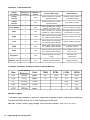
Alarm Conditions
. . . . . . . . . . . . . . . . . . . . . . . . . . . . . . .
. . . . . . .
1
8
Preset Alarm Limits and Calibration
. . . . . . . . . . . . . . . . . . . . . . .
1
8
Back Light
. . . . . . . . . . . . . . . . . . . . . . . . . . . . . . .
. . . . . . . . . . . .
1
8
Sampling Pump
. . . . . . . . . . . . . . . . . . . . . . . . . . . . . . .
. . . . . . . .
1
9
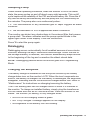
Datalogging
. . . . . . . . . . . . . . . . . . . . . . . . . . . . . . .
. . . . . . . . . . .
1
9
Charging the EntryRAE
. . . . . . . . . . . . . . . . . . . . . . . . . . . . . . .
. .
1
9
Table of Contents

f
T
he Li-Ion Battery Pack
. . . . . . . . . . . . . . . . . . . . . . . . . . . . . . .
. .
21
Programming Mode
. . . . . . . . . . . . . . . . . . . . . . . . . . . . . . .
. . . . . . .
21
Security
. . . . . . . . . . . . . . . . . . . . . . . . . . . . . . .
. . . . . . . . . . . . . .
21
Programming Menus
. . . . . . . . . . . . . . . . . . . . . . . . . . . . . . .
. . . .
22
Entering Program Mode
. . . . . . . . . . . . . . . . . . . . . . . . . . . . . . .
.
23
Change Monitor Setup
. . . . . . . . . . . . . . . . . . . . . . . . . . . . . . .
. .
2
3
Maintenance
. . . . . . . . . . . . . . . . . . . . . . . . . . . . . . .
. . . . . . . . . . . .
2
7
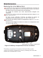
Replacing the Li-Ion Battery Pack
. . . . . . . . . . . . . . . . . . . . . . . . .
2
7
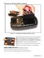
Emergency Alkaline Battery Adapter
. . . . . . . . . . . . . . . . . . . . . . .
2
9
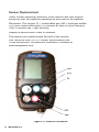
Sensor Replacement
. . . . . . . . . . . . . . . . . . . . . . . . . . . . . . .
. . .
30
CO Sensor Charcoal Filter
. . . . . . . . . . . . . . . . . . . . . . . . . . . . . .
32
Cleaning the PID
. . . . . . . . . . . . . . . . . . . . . . . . . . . . . . .
. . . . . . .
33
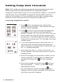
Setting Pump Stall Threshold
. . . . . . . . . . . . . . . . . . . . . . . . . . . . . .
34
Specifications
. . . . . . . . . . . . . . . . . . . . . . . . . . . . . . .
. . . . . . . . . . .
3
5
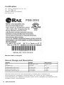
Certifications
. . . . . . . . . . . . . . . . . . . . . . . . . . . . . . .
. . . . . . . . . .
36
Sensor Range and Resolution
. . . . . . . . . . . . . . . . . . . . . . . . . . .
3
6
Service and Repair Record
. . . . . . . . . . . . . . . . . . . . . . . . . . . . . . .
.
3
7
SPECIAL NOTE:
If the monitor needs to be serviced, contact either:
The
RAE Systems distributor
where the monitor was purchased; they will
RAE Systems distributor where the monitor was purchased; they will RAE Systems distributor
return the monitor on your behalf,
or
The
RAE Systems Technical Service department
. Before returning the
monitor for service or repair, obtain a Returned Material Authorization (RMA)
number for proper tracking of your equipment. This number needs to be on
all documentation and posted on the outside of the box in which the monitor
is returned for service or upgrade.
Packages without RMA Numbers will be
refused at the factory.

General Information
1
General Information
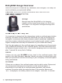
The EntryRAE is a 4-gas plus PID (photoionization detector) gas moni-
tor. Reliable, easy to operate and simple to calibrate, the EntryRAE
delivers added protection without added complexity.
Simple, Modular, Durable PID
RAE Systems is the technology leader in PIDs. Our modular, plug &
play, self-cleaning (patented) PID is the most reliable and durable PID
available today.
Key Features
•
Reliable self-cleaning PID
•
Also includes CO, H
2
S, LEL and O
2
sensors
•
Built-in pump
•
Ι
nterchangeable Li-Ion and alkaline battery adapter
•
Up to 16 hours of continuous operation
•
Large, easy-to-read display
•
Datalogging
•
Visual alarm with bright red flashing LEDs
•
Loud audible alarms (95dB at 30 cm)
•
Rugged weather-resistant composite case

2
General Information
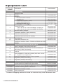
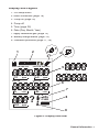
Equipment List
Photo Item
Number
Part Name
Part Number
Monitor Only
*Shipping case
2
Monitor
701-3040-000
Sensors
Photoionization Detector
023-0102-000
Oxygen (O
2
2
2
2
2
)
046-1161-000
Combustible (%LEL, %Vol)
014-0212-000
Carbon Monoxide (CO)
032-0200-000
Hydrogen Sulfide (H
2
2
2
2
2
S)
032-0202-000
Rechargeable Li-Ion Battery
046-3007-000
3
Charging Cradle
- 120 V AC to 12 V DC wall charger, US plug or
- 230 V AC to 12 V DC wall charger, Euro plug
046-3059-000
500-0036-000
500-0036-001
4
Alkaline Battery Adapter
046-3051-000
5
Calibration Adapter/Tubing Assembly
046-3040-000
7
External Filters (5-pack)
046-3022-005
Charcoal Filters (for the CO Sensor)
008-3006-005
8
User Manual
046-4001-000
12
EntryRAE Resource CD
046-4013-000
Computer Interface Cable - RS232 to RS232 with USB
adapter
Optional Confined Space Kit II (CSK II) 046-0911-000
1
Hard Transport Case with precut foam
002-3009-000
9
Remote Sampling Probe with 15 feet (5 meters) of
self-coiling Teflon (tm) tubing
008-3015-002
5
Tool Kit
081-0005-000
10
Four-Gas Mix in a 34-Liter cylinder (50% LEL, 20.9%
O
2
, 10 ppm H
2
S, 50 ppm CO)
600-0050-004
11
100 ppm Isobutylene Gas in a 34 L cylinder
600-0002-000
6
Regulator (male) with tubing
007-3021-000
6
Regulator (female) with tubing
002-3011-000
Optional Guaranteed Cost of Ownership
4-year repair and replacement guarantee
SVC-PTC4-046
Optional Accessories (items sold separately)
not shown
AutoRAE Docking Station Starter Kit
048-5900-000
not shown
Additional AutoRAE Cradle
048-0154-000
not shown
PID Cleaning Kit
500-0014-010
* Different shipping cases are used for monitor-only and calibration kits.

General Information
3
1
8
5
5, 6
5, 6
10 7 2 4 11
9
12
3
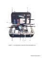
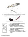
Figure 1. The EntryRAE Optional Confined Space Kit.

4
General Information
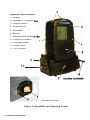
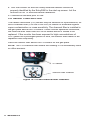
Physical Description
Physical Description
1. Display
2. Operation / Program keys
2. Operation / Program keys
3. Charge status
4. Visual alarm
5. Gas plate
6. Buzzer
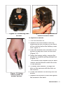
7. Gas inlet with external filter
7. Gas inlet with external filter
8. Charging contacts
9. Charging cradle
10. Power jack
11. RS-232 port
9
7
11
4
5
6
8
2
1
10
3
bottom of monitor
Figure 2. EntryRAE and Charging Cradle.
monitor in cradle

General Information
5
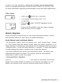
Display and Legend
1. PID lamp alarm
2. Alarm conditions (
page 18
)
3. Pump on (
page 19
)
4. Pump off
5. Time (
page 25
)
6. Date (Day, Month, Year)
7. Apply calibration gas (
page 12
)
8. Battery charge status (
page 19
)
9. Password protected (
page 11, 26
)
HIGHLOW TWA STEL
D1
D2
D3
D4
D5
D6
D7
D8
D9
D10
D11
D12
D13
D14
D15
D16
D17
A
B
C
D
E
F
G
ALARM
H S2 ppm
CO ppm
VOC ppm
LEL %VOL
O2 %VOL
.
D M Y
:
HIGHLOW TWA STEL
HIGHLOW TWA STEL
HIGHLOW HIGHLOW
.
?
S
PAN
Z
E
R
O
OVER
S
E
R
O
S
E
R
O
D8
D9
D10
D11
D12
D13
D M Y
7
4
5
6
2
1
3
D4
D5
D6
D7
:
9
8
Figure 3. Display Overview.

6
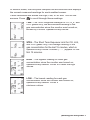
Operating the EntryRAE
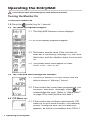
3.1
The time is shown in 24-hour format, and the
date is shown in “ddmmyy” format.
3.2 If the monitor has never been programmed, you
will see a “date error” message. Press @ to
acknowledge the error. (Refer to “Adjust Date?”
on page 20 to reset the time and date.)
3.0 The
Time and Date settings are checked:
Operating the EntryRAE
The external filter must always be used with the monitor.
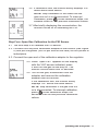
Turning the Monitor On
!
2.1 The EntryRAE firmware version displays.
2.2 All of the display segments appear.
2.3 The buzzer sounds twice (if the unit has not
been set to run silently; see page 24), the LEDs
blink twice, and the vibration alarm turns on and
off.
2.4 The preset alarm limits appear in order:
HIGH, LOW, TWA, STEL.
To turn the monitor on
:
1.0
Press the @ (mode) key for 1 second.
2.0 The warm-up sequence begins:
4.0 PID Warm-up:
4.1 If the monitor has not been used recently, PID
warm-up of up to three minutes (180 seconds)
occurs. During this time, the PID lamp icon
appears, as well as a countdown from 180 to 1.

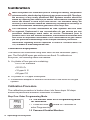
Operating the EntryRAE
7
Operating the EntryRAE 7Operating the EntryRAE
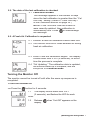
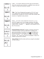
5.1
Calibration Needed
This message appears if the number of days
since the last calibration is greater than the “Cal
Due Day” setting. (Refer to “Calib Due Day?”
in the Calibration section on page 24.)
NOTE:
If the Time and Date are invalid or
were recently updated, then calibration is
automatically due. Press @ to acknowledge
the message.
6.1
Perform a fresh air calibration before each use.
6.2 The monitor must be in clean ambient air during
fresh air calibration.
6.3 Press
Y
and the calibration begins. The display
Y and the calibration begins. The display Y
counts down from 5 to 0 (6 seconds), at which
time the process is complete.
6.4 “Cal Updating.” The calibration data is updated,
the monitor warm-up is complete, and the
EntryRAE is in
Monitor Mode
.
5.0 The date of the last calibration is checked
:
6.0 A
Fresh Air Calibration
is requested
1.0
Press the @ button for 5 seconds.
Turning the Monitor Off
The monitor cannot be turned off until after the warm-up sequence is
completed.
To
turn the monitor off
:
1.1
The display counts down from 3 to 1
(3 seconds), and flashes the LED for each
count.
1.2
Release @ when “Unit Off” appears on the
display.

8
Operating the EntryRAE
Monitor Mode
In Monitor Mode, the EntryRAE samples the environment and displays
real-time readings for each enabled sensor.
The Pump Cycle
Under normal operating conditions, when the monitor is not in an alarm
state, the pump cycles on and off about every 8 seconds. This on/off cycle
improves the reliability of the PID and saves battery life.
The pump runs continuously when:
1.0 The concentration of any measured gas or vapor triggers an alarm
condition.
2.0 When the concentration of VOCs is nearing an alarm condition.
Continuous Operation of the Pump
Pressing the
Y
key and the
N
key simultaneously causes the pump to run
continuously for 5 minutes. This value can be changed using the ProRAE
Studio software.
Detecting Gases and Vapors Real-time
CAUTION:
HIGH OFF-SCALE READINGS MAY INDICATE AN
EXPLOSIVE CONCENTRATION.
ATTENTION:
LES LECTURES HORS ÉCHELLE ÉLEVÉES PEUVENT
INDIQUER UNE CONCENTRATION EXPLOSIVE.

Operating the EntryRAE
9
Operating the EntryRAE 9Operating the EntryRAE
In Monitor Mode, the EntryRAE samples the environment and displays
the current measured readings for each enabled sensor.
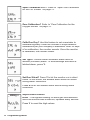
It also calculates and stores the High, Low, STEL and TWA for the
sensors. Press @ to scroll through these readings:
STEL
- The Short Term Exposure Limit for CO, H
2
S,
and VOC gases only; the average reading of the
gas concentration for the last 15 minutes, which is
updated every minute. Dashes (“- - -”) appear for the
first 15 minutes.
TWA
- The Time Weighted Average for CO, H
2
S, and
VOC gases only; the accumulated reading of the
gas concentration since the monitor was turned on,
divided by 8 hours. Updated every minute.
LOW
– The lowest reading for each gas
concentration since the monitor was turned on;
updated every second. Press
Y
to reset the
Y to reset the Y
minimum values.
HIGH
- The highest reading for each gas
concentration since the monitor was turned on;
updated every second. Press
Y
to reset the high
values.
L
O
W
L
O
W
LOW
LOW

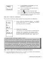
10
Operating the EntryRAE
1.0 The monitor must be in Programming Mode
for calibration.
1.1 Press and hold @ and
N
for 3 seconds to
enter Programming.
1.2 Password Enabled Monitors.
Calibration
While EntryRAEs are calibrated prior to leaving the factory, temperature
extremes and/or shocks during shipment can cause sensor drift. Therefore,
the accuracy of any newly purchased RAE Systems monitor should be
tested by exposing the sensor(s) to known concentration calibration gas
before the monitor is used or put into service. For maximum safety, the
accuracy of the monitor should be checked by exposing the sensor(s) to
known concentration calibration gas before each day’s use.
Les indications de toute instruments de RAE Systems doit être testé
en exposant l’instrument à une concentration de gaz connue par une
procédure dietalonnage avant metre en service l’instrument pour la
première fois. Pour une sécurité maximale, la sensibilité du EntreRAE doit
être vérifie en exposant l’instrument à une concentration de gaz connue
par une procédure diétalonnage avant chaque utilisation journaliere.
Information regarding sensor expiration is listed in Technical Note TN-
114, available at www.raesystems.com.
Calibration Equipment
The sensors are calibrated using both fresh air and calibration (span)
gas. The EntryRAE span gas mixtures are xed. To calibrate an
EntryRAE, the following items are needed:
A. A cylinder of four-gas mix containing:
s
50% LEL methane
s
20.9% O
2
s
10 ppm H
2
S
s
50 ppm CO
B. A cylinder of 100 ppm isobutylene.
C. A calibration adapter to connect the monitor to the outlet of the gas
cylinder.
Calibration Procedure
The calibration procedure is broken down into three steps. All steps
should be performed whenever calibration is needed.
Step One: Enter Programming Mode
!
!

Operating the EntryRAE
11
Operating the EntryRAE 11Operating the EntryRAE
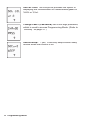
1.2.1
If a password is enabled
, you are
prompted to enter one.
1.2.2 Use
Y
to increase the digit and
N
to
decrease the digit.
1.2.3 Use @ to move to the next digit.
1.2.4 Press @ and
Y
to enter the password.
1.2.5 If the password is incorrect, the monitor
returns to Monitor mode.
!
2.1 Press
Y
and the calibration begins. The display
Y and the calibration begins. The display Y
counts down from 5 to 1 (5 seconds), at which
time the process is complete.
2.2
Calibration Updating
The monitor is in the process of calibrating the
sensors. As it completes, the display shows
the sensors registering zero (or 20.9% for O
2
),
before it moves to the next step, “Span Cal?”
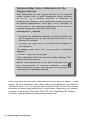
Using External Zeroing Organic Filters
Use an external zero organic filter (P/N 008-3024-000, 3-pack) if the
ambient air may be contaminated with hydrocarbons. Attach the filter
to the EntryRAE during fresh air calibration. The filter can be used up
to 20 times before disposing. This filter removes most heavier organic
and inorganic compounds, but may not completely remove lighter
compounds such as methane, propane and CO. Note that the filter
should be attached to the EntryRAE before the calibration adapter.
Step Three: Span Gas Calibration for Multiple Sensors
3.0 For this calibration step, the LEL, CO and H
2
S sensors are calibrated
using the 4-gas mix (P/N 600-0050-004).
Step Two: Fresh Air Calibration
The monitor must be in clean ambient air during fresh air calibration.

12
Operating the EntryRAE
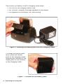
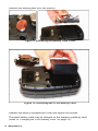
3.1 Connect the calibration adapter to the EntryRAE and put a regulator
(500 cc per minute flow rate) on the 4-gas mix cylinder.
3.2 After “Span Cal?” appears on the display with the
CO, H
2
S, and LEL sensors indicated, press
Y.
3.3 Turn the gas all the way on.
3.3 Connect the open end of the calibration
adapter to the regulator.
The monitor starts to
countdown from 70 seconds.
3.4
When the countdown timer reaches zero, turn
off the gas, and disconnect the calibration
adapter from the regulator.
3.5 Compare the readings displayed to the span
gas values indicated on the gas cylinder. The
readings should closely agree with the span gas
values.
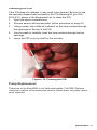
Figure 6. EntryRAE Connected to Calibration Gas.
Figure 5. Calibration Adapter.
Figure 4. Gas Cylinded with Regulator.

Operating the EntryRAE
13
Operating the EntryRAE 13Operating the EntryRAE
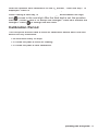
Step Four: Span Gas Calibration for the PID Sensor
4.1 The final step is to calibrate the PID sensor.
4.2 Connect the EntryRAE calibration adapter to the monitor (see Figure
6) and put a regulator (500 cc per minute flow rate) on the cylinder of
isobutylene.
4.3 Connect the open end of the calibration adapter to the regulator.
3.6 If calibration fails, the monitor briefly displays “Err”
above each failed sensor.
NOTE:
Stop calibration in the event that the
gas runs out or is disconnected. To interrupt
calibration, press @ . When calibration stops, the
sensors revert to their previous calibration values.
3.7 After briefly displaying the concentration, the
monitor moves on to calibrating the PID.
4.4 When “Span Cal?” appears on the display
with the VOC sensor indicated, press
Y
and turn the gas all the way on. The
monitor counts down from 30 seconds.
4.5 Turn off the gas, dicsconnect from the
adapter, and remove the calibration
adapter from the monitor.
If the calibration fails, the monitor briefly
displays “Err” above the failed sensor.
NOTE:
Stop calibration if the gas runs out
or is disconnected. To interrupt calibration,
press @. When calibration stops, the
sensors revert to their previous calibration
values.

14
Operating the EntryRAE
Optional Step: Zero Calibration for the
Oxygen Sensor
Zero calibration for the oxygen sensor is not required
under normal use. A span calibration using ambient
air (20.9% O
2
) is usually sufficient to establish its
performance. However, zero calibration may be required
for special applications. Zero gas (100% nitrogen) is
not included in the standard calibration kit and may be
ordered separately (P/N 600-0062-000).
Zeroing the O
2
Sensor
s
Connect the calibration adapter to the EntryRAE and
put a regulator (500 cc per minute flow rate) on the
cylinder of nitrogen.
s
Connect the open end of the calibration adapter to
the regulator.
The display reads “Zero Cal?” and only the O
2
segment
appears.
s
Press
Y
and turn on the gas.
If the calibration fails, the monitor briefly displays “Err”
above the failed sensor.
NOTE:
Stop calibration in the event that gas runs out
or is disconnected. To interrupt calibration, press @ .
When calibration stops, the sensors will revert back to
their previous calibration values.
Note that each sensor has cross-sensitivities to several gases. These
gases, sensor sensitivity, and other sensor specifications are listed in
Technical Note TN-114, Sensor Specifications And Cross-Sensitivities,
available at www.raesystems.com. Information regarding LEL sensor
poisons is located in Technical Note TN-144, Handling LEL Sensor
Poisons, also available at www.raesystems.com.
La page est en cours de chargement...
La page est en cours de chargement...
La page est en cours de chargement...
La page est en cours de chargement...
La page est en cours de chargement...
La page est en cours de chargement...
La page est en cours de chargement...
La page est en cours de chargement...
La page est en cours de chargement...
La page est en cours de chargement...
La page est en cours de chargement...
La page est en cours de chargement...
La page est en cours de chargement...
La page est en cours de chargement...
La page est en cours de chargement...
La page est en cours de chargement...
La page est en cours de chargement...
La page est en cours de chargement...
La page est en cours de chargement...
La page est en cours de chargement...
La page est en cours de chargement...
La page est en cours de chargement...
La page est en cours de chargement...
La page est en cours de chargement...
-
 1
1
-
 2
2
-
 3
3
-
 4
4
-
 5
5
-
 6
6
-
 7
7
-
 8
8
-
 9
9
-
 10
10
-
 11
11
-
 12
12
-
 13
13
-
 14
14
-
 15
15
-
 16
16
-
 17
17
-
 18
18
-
 19
19
-
 20
20
-
 21
21
-
 22
22
-
 23
23
-
 24
24
-
 25
25
-
 26
26
-
 27
27
-
 28
28
-
 29
29
-
 30
30
-
 31
31
-
 32
32
-
 33
33
-
 34
34
-
 35
35
-
 36
36
-
 37
37
-
 38
38
-
 39
39
-
 40
40
-
 41
41
-
 42
42
-
 43
43
-
 44
44


Rae EntryRAE PGM-3000 Manuel utilisateur
- Taper
- Manuel utilisateur
dans d''autres langues
- English: Rae EntryRAE PGM-3000 User manual
Autres documents
-
Altair 5X Multigas Detector Le manuel du propriétaire
-
BW Technologies MicroClip XT Quick Reference Manual
-
RIDGID Détecteur de gaz combustible micro CD-100 Manuel utilisateur
-
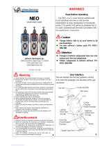 mPower Electronics Neo Guide de démarrage rapide
-
Honeywell BW Max XT ll Multi Gas Detector Mode d'emploi
-
 Ion Science Tiger LT handheld VOC detector Manuel utilisateur
-
Honeywell XXYY-BW-Ultra Mode d'emploi
-
Honeywell FS0502098 Mode d'emploi
-
-
MSA PrimaX® IR Gas Transmitter Mode d'emploi

