
TLP 1000MV and TLP 1000TV
User Guide
TouchLink™
TouchLink Touchpanel Control Systems
68-1909-01 Rev. C
03 20

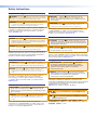
Safety Instructions • English
WARNING: This symbol, , when used on the product, is intended to
alert the user of the presence of uninsulated dangerous voltage within the
product’s enclosure that may present a risk of electric shock.
ATTENTION: This symbol, , when used on the product, is intended
to alert the user of important operating and maintenance (servicing)
instructions in the literature provided with the equipment.
For information on safety guidelines, regulatory compliances, EMI/EMF
compatibility, accessibility, and related topics, see the Extron Safety and
Regulatory Compliance Guide, part number 68-290-01, on the Extron
website, www.extron.com.
Sicherheitsanweisungen • Deutsch
WARNUNG: Dieses Symbol auf dem Produkt soll den Benutzer darauf
aufmerksam machen, dass im Inneren des Gehäuses dieses Produktes
gefährliche Spannungen herrschen, die nicht isoliert sind und die einen
elektrischen Schlag verursachen können.
VORSICHT: Dieses Symbol auf dem Produkt soll dem Benutzer in
der im Lieferumfang enthaltenen Dokumentation besonders wichtige
Hinweise zur Bedienung und Wartung (Instandhaltung) geben.
Weitere Informationen über die Sicherheitsrichtlinien, Produkthandhabung,
EMI/EMF-Kompatibilität, Zugänglichkeit und verwandte Themen finden Sie
in den Extron-Richtlinien für Sicherheit und Handhabung (Artikelnummer
68-290-01) auf der Extron-Website, www.extron.com.
Instrucciones de seguridad • Español
ADVERTENCIA: Este símbolo, , cuando se utiliza en el producto,
avisa al usuario de la presencia de voltaje peligroso sin aislar dentro del
producto, lo que puede representar un riesgo de descarga eléctrica.
ATENCIÓN: Este símbolo, , cuando se utiliza en el producto, avisa
al usuario de la presencia de importantes instrucciones de uso y
mantenimiento recogidas en la documentación proporcionada con el
equipo.
Para obtener información sobre directrices de seguridad, cumplimiento
de normativas, compatibilidad electromagnética, accesibilidad y
temas relacionados, consulte la Guía de cumplimiento de normativas
y seguridad de Extron, referencia 68-290-01, en el sitio Web de Extron,
www.extron.com.
Instructions de sécurité • Français
AVERTISSEMENT : Ce pictogramme, , lorsqu’il est utilisé sur le
produit, signale à l’utilisateur la présence à l’intérieur du boîtier du
produit d’une tension électrique dangereuse susceptible de provoquer
un choc électrique.
ATTENTION : Ce pictogramme, , lorsqu’il est utilisé sur le produit,
signale à l’utilisateur des instructions d’utilisation ou de maintenance
importantes qui se trouvent dans la documentation fournie avec le
matériel.
Pour en savoir plus sur les règles de sécurité, la conformité à la
réglementation, la compatibilité EMI/EMF, l’accessibilité, et autres sujets
connexes, lisez les informations de sécurité et de conformité Extron, réf.
68-290-01, sur le site Extron, www.extron.com.
Istruzioni di sicurezza • Italiano
AVVERTENZA: Il simbolo, , se usato sul prodotto, serve ad
avvertire l’utente della presenza di tensione non isolata pericolosa
all’interno del contenitore del prodotto che può costituire un rischio di
scosse elettriche.
ATTENTZIONE: Il simbolo, , se usato sul prodotto, serve ad avvertire
l’utente della presenza di importanti istruzioni di funzionamento e
manutenzione nella documentazione fornita con l’apparecchio.
Per informazioni su parametri di sicurezza, conformità alle normative,
compatibilità EMI/EMF, accessibilità e argomenti simili, fare riferimento
alla Guida alla conformità normativa e di sicurezza di Extron, cod. articolo
68-290-01, sul sito web di Extron, www.extron.com.
Instrukcje bezpieczeństwa • Polska
OSTRZEŻENIE: Ten symbol, , gdy używany na produkt, ma na celu
poinformować użytkownika o obecności izolowanego i niebezpiecznego
napięcia wewnątrz obudowy produktu, który może stanowić zagrożenie
porażenia prądem elektrycznym.
UWAGI: Ten symbol, , gdy używany na produkt, jest przeznaczony do
ostrzegania użytkownika ważne operacyjne oraz instrukcje konserwacji
(obsługi) w literaturze, wyposażone w sprzęt.
Informacji na temat wytycznych w sprawie bezpieczeństwa, regulacji wzajemnej
zgodności, zgodność EMI/EMF, dostępności i Tematy pokrewne, zobacz Extron
bezpieczeństwa i regulacyjnego zgodności przewodnik, część numer 68-290-01,
na stronie internetowej Extron, www.extron.com.
Инструкция по технике безопасности • Русский
ПРЕДУПРЕЖДЕНИЕ: Данный символ, , если указан
на продукте, предупреждает пользователя о наличии
неизолированного опасного напряжения внутри корпуса
продукта, которое может привести к поражению
электрическим током.
ВНИМАНИЕ: Данный символ, , если указан на продукте,
предупреждает пользователя о наличии важных инструкций
по эксплуатации и обслуживанию в руководстве,
прилагаемом к данному оборудованию.
Для получения информации о правилах техники безопасности,
соблюдении нормативных требований, электромагнитной
совместимости (ЭМП/ЭДС), возможности доступа и других вопросах
см. руководство по безопасности и соблюдению нормативных
требований Extron на сайте Extron: ,
www.extron.com, номер по каталогу - 68-290-01.
安全说明 • 简体中文
警告: 产品上的这个标志意在警告用户该产品机壳内有暴露的危险 电压,
有触电危险。
注意: 产品上的这个标志意在提示用户设备随附的用户手册中有
重要的操作和维护(维修)说明。
关于我们产品的安全指南、遵循的规范、EMI/EMF 的兼容性、无障碍
使用的特性等相关内容,敬请访问 Extron 网站 , www.extron.com,参见 Extron
安全规范指南,产品编号 68-290-01
。
Safety Instructions

Copyright
© 2015 - 2020 Extron Electronics. All rights reserved.
Trademarks
All trademarks mentioned in this guide are the properties of their respective owners.
The following registered trademarks (
®
), registered service marks (
SM
), and trademarks (
TM
) are the property of RGBSystems, Inc. or
ExtronElectronics (see the current list of trademarks on the Terms of Use page at www.extron.com):
Registered Trademarks
(
®
)
Cable Cubby, ControlScript, CrossPoint, DTP, eBUS, EDID Manager, EDID Minder, Extron, Flat Field, FlexOS, Glitch Free, Global Configurator,
Global Scripter, GlobalViewer, Hideaway, HyperLane, IPIntercom, IPLink, Key Minder, LinkLicense, LockIt, MediaLink, MediaPort, NetPA,
PlenumVault, PoleVault, PowerCage, PURE3, Quantum, ShareLink, Show Me, SoundField, SpeedMount, SpeedSwitch, StudioStation,
System INTEGRATOR, TeamWork, TouchLink, V-Lock, VideoLounge, VN-Matrix, VoiceLift, WallVault, WindoWall, XPA, XTP, XTP Systems, and
ZipClip
Registered Service Mark(SM) : S3 Service Support Solutions
Trademarks
(
™
)
AAP, AFL (Accu-Rate Frame Lock), ADSP (Advanced Digital Sync Processing), Auto-Image, AVEdge, CableCover, CDRS (Class D
Ripple Suppression), Codec Connect, DDSP (Digital Display Sync Processing), DMI (Dynamic Motion Interpolation), DriverConfigurator,
DSPConfigurator, DSVP (Digital Sync Validation Processing), eLink, EQIP, Everlast, FastBite, Flex55, FOX, FOXBOX, IP Intercom HelpDesk,
MAAP, MicroDigital, Opti-Torque, PendantConnect, ProDSP, QS-FPC (QuickSwitch Front Panel Controller), Room Agent, Scope-Trigger, SIS,
Simple Instruction Set, Skew-Free, SpeedNav, Triple-Action Switching, True4K, True8K, Vector™ 4K, WebShare, XTRA, and ZipCaddy
安全記事 • 繁體中文
警告: 若產品上使用此符號,是為了提醒使用者,產品機殼內存在著
可能會導致觸電之風險的未絕緣危險電壓。
注意 若產品上使用此符號,是為了提醒使用者,設備隨附的用戶手冊中有
重 要 的 操 作 和 維 護( 維 修 )説 明 。
有關安全性指導方針、法規遵守、EMI/EMF 相容性、存取範圍和相關主題的詳細資
訊,請瀏覽 Extron 網站:www.extron.com,然後參閱《Extron 安全性與法規
遵守手冊》,準則編號 68-290-01。
安全上のご注意
• 日本語
警告: この記号 が製品上に表示されている場合は、筐体内に絶縁されて
いない高電圧が流れ、感電の危険があることを示しています。
注意:この記号 が製品上に表示されている場合は、本機の取扱説明書に
記載されている重要な操作と保守(整備)の指示についてユーザーの注意
を喚起するものです。
安全上のご注意、法規厳守、EMI/EMF適合性、その他の関連項目に
つ い て は 、エ ク スト ロ ン の ウェブ サ イト www.extron.com よ り 『 Extron Safety
and Regulatory Compliance Guide』 ( P/N 68-290-01) をご覧ください。
안전 지침 • 한국어
경고: 이 기호 가 제품에 사용될 경우, 제품의 인클로저 내에 있는
접지되지 않은 위험한 전류로 인해 사용자가 감전될 위험이 있음을
경고합니다.
주의: 이 기호 가 제품에 사용될 경우, 장비와 함께 제공된 책자에 나와
있는 주요 운영 및 유지보수(정비) 지침을 경고합
니다.
안전 가이드라인, 규제 준수, EMI/EMF 호환성, 접근성, 그리고 관련 항목에
대한 자세한 내용은 Extron 웹 사이트(www.extron.com)의 Extron 안전 및
규제 준수 안내서, 68-290-01 조항을 참조하십시오.

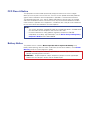
FCC Class A Notice
This equipment has been tested and found to comply with the limits for a Class A digital
device, pursuant to part15 of the FCC rules. The ClassA limits provide reasonable protection
against harmful interference when the equipment is operated in a commercial environment.
This equipment generates, uses, and can radiate radio frequency energy and, if not installed
and used in accordance with the instruction manual, may cause harmful interference to radio
communications. Operation of this equipment in a residential area is likely to cause interference;
the user must correct the interference at his own expense.
NOTE:
• This unit was tested with shielded I/O cables on the peripheral devices. Shielded cables
must be used to ensure compliance with FCC emissions limits.
• For more information on safety guidelines, regulatory compliances, EMI/EMF
compatibility, accessibility, and related topics, see the Extron Safety and Regulatory
Compliance Guide
on the Extron website.
Battery Notice
This product contains a battery. Do not open the unit to replace the battery. If the
battery needs replacing, return the entire unit to Extron (for the correct address, see the Extron
Warranty section on the last page of this guide).
CAUTION: Risk of Explosion if Battery is replaced by an Incorrect Type. Dispose of Used
Batteries According to the Instructions.
ATTENTION : Risque d’explosion. Ne pas remplacer la pile par le mauvais type de pile.
Débarrassez-vous des piles utilisées selon le mode d’emploi.

Conventions Used in this Guide
Notifications
In this user guide, the following are used:
WARNING: Potential risk of severe injury or death.
AVERTISSEMENT : Risque potentiel de blessure grave ou de mort.
CAUTION: Risk of minor personal injury.
ATTENTION : Risque de blessuremineure.
ATTENTION:
•
Risk of property damage.
• Risque de dommages matériels.
NOTE: A note draws attention to important information.
Software Commands
Commands are written in the fonts shown here:
^AR Merge Scene,,Op1 scene 1,1 ^B 51 ^W^C
[01] R 0004 00300 00400 00800 00600 [02] 35 [17] [03]
E
X!
*
X1&
*
X2)
*
X2#
*
X2!
CE
}
NOTE: For commands and examples of computer or device responses mentioned
in this guide, the character “0” is used for the number zero and “O” represents the
capital letter “o”.
Computer responses and directory paths that do not have variables are written in the font shown
here:
Reply from 208.132.180.48: bytes=32 times=2ms TTL=32
C:\Program Files\Extron
Variables are written in slanted form as shown here:
ping xxx.xxx.xxx.xxx —t
SOH R Data STX Command ETB ETX
Selectable items, such as menu names, menu options, buttons, tabs, and field names are written
in the font shown here:
From the File menu, select New.
Click the OK button.
Specifications Availability
Product specifications are available on the Extron Website, www.extron.com.
Extron Glossary of Terms
A glossary of terms is available at www.extron.com/technology/glossary.aspx.


Contents
Introduction............................................................ 1
TLP 1000MV and TLP 1000TV ................................1
Features .................................................................. 1
Requirements ..........................................................3
Software .............................................................3
Hardware ............................................................3
Panel Features ...................................................... 4
TLP 1000MV Front Panel Features .......................... 4
Reset Buttons and LED .......................................5
TLP 1000MV Rear Panel Features
and Connections ....................................................6
TLP 1000TV Front Panel Features
and Operations ....................................................11
TLP 1000TV Rear Panel Features
and Connections ..................................................12
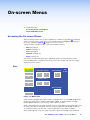
On-screen Menus ............................................... 16
Accessing the On-screen Menus ...........................16
Main Screen ......................................................16
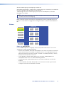
Volume Screen .................................................. 17
Time Screen......................................................18
Network Screen ................................................18
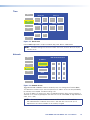
Video Screen ....................................................19
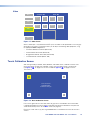
Touch Calibration Screen ......................................19
Configuration Software ..................................... 20
The Configuration Software ...................................20
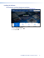
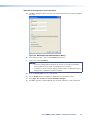
Installing the Software ...........................................20
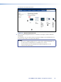
GUI Configurator and Global Configurator
Installation ........................................................20
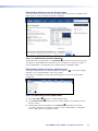
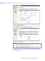
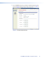
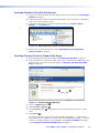
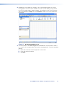
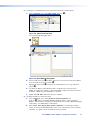
Using the TouchLink Panel Web Pages .................21
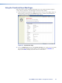
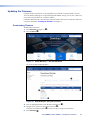
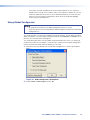
Updating the Firmware ..........................................23
Updating Firmware Using
Extron Firmware Loader ...................................23
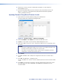
Updating Firmware Using GUI Configurator ....... 24
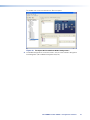
Updating Firmware From a Web Browser .......... 25
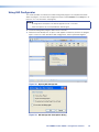
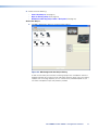
Using GUI Configurator .........................................26
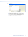
Using Global Configurator .....................................31
Mounting ............................................................... 37
Rack Mounting the TLP 1000MV ..........................37
Underwriters Laboratories Guidelines for
Rack Mounting ................................................37
Rack Mounting the TLP 1000MV ......................37
Wall Mounting the TLP 1000MV ............................38
Wall Mounting the TLP 1000MV Directly
into the Wall .....................................................38
Wall Mounting the TLP 1000MV
with a Wall Box ................................................39
Furniture Mounting the TLP 1000MV ..................... 40
Desktop Mounting the TLP1000TV ......................41
Freestanding .....................................................41
Swivel Mount Adapter .......................................41
Removing the TLP 1000TV Base for
VESA Mounting ....................................................42
VESA Mounting the TLP 1000TV ...........................43
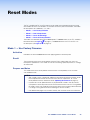
Reset Modes ........................................................ 44
Mode 1 — Use Factory Firmware .......................... 44
Activation ..........................................................44
Result ...............................................................44
Purpose and Notes ...........................................44
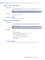
Mode 3 — Run or Stop Events .............................45
Activation ..........................................................45
Result ...............................................................45
Purpose and Notes ...........................................45
Mode 4 — Reset all IP Settings ............................. 45
Activation ..........................................................45
Result ...............................................................45
Purpose and Notes ...........................................45
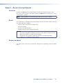
Mode 5 — Reset to Factory Defaults.....................46
Activation ..........................................................46
Result ...............................................................46
Purpose and Notes ...........................................46
TLP 1000MV and TLP 1000TV • Contents vii

TLP 1000MV and TLP 1000TV • Contents viii

Introduction
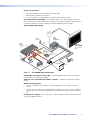
This guide describes the function, installation and operation of the TouchLink TLP1000MV
and TLP 1000TV panels. Unless otherwise stated, the terms “TLP 1000 Series,” “TLP1000,”
“touchpanel,” and “TouchLink touchpanel” refer to both models. The guide also provides
information about optional accessories that are available from Extron for both touchpanels.
This section provides information about:
• TLP 1000MV and TLP 1000TV
• Features
• Requirements
TLP 1000MV and TLP 1000TV
Both units have a 10.1 inch widescreen display with a resolution of 1024x600. The screen
displays graphic objects and text, which are associated with user-defined functions. The touch
overlay allows the user to initiate or activate functions by touching the objects on the screen.
The TLP 1000MV is a wall- or rack-mounted TouchLink touchpanel. The TLP 1000TV comes
with a stand that allows it to be placed on a desktop. If the stand is removed, the unit can be
VESA
®
mounted on a wall or furniture, using the optional Extron mounting kit.
A motion sensor, light sensor, and two speakers provide sleep mode, auto dimming, and audible
feedback.
Extron GUI Configurator software allows the user to design the screen layout by selecting from
existing templates or designing entirely new interfaces on their PC and uploading the completed
project to the TouchLink panel. Functions are assigned to the screen objects with the Extron
Global Configurator software. The user can define the graphics and the functions associated with
those graphics, providing versatility and adaptability to the configuration and control of an AV
system.
Features
10-inch color touchscreen — with 1024x600 resolution and 18-bit color depth.
Full-motion video display — for preview and monitoring, using Extron twisted pair technology.
Built-in MTP — a twisted pair receiver accepts either S-video or composite video signals over
standard CAT 5-type cable. This provides flexibility of integration and aids cable management by
minimizing the number of connections to the touchpanel.
Compatibe with all Extron IP Link products — for easy integration into existing systems.
NOTE: These products are not compatible with the Extron Pro series of devices.
Ethernet connection — provides an inexpensive, easily installed, cabling option for connecting
to other devices on the network.
Power over the Ethernet (PoE) — allows the touchpanel to receive power and control over
a single Ethernet cable, eliminating the need for a local power supply. The power injector is
included.
Built-in speakers — provide audio for the full-motion video preview and audible feedback from
button presses.
TLP 1000MV and TLP 1000TV • Introduction 1

Energy saving features —
• Adjustable sleep timer puts touchpanel into sleep mode.
• Motion detector wakes the touchpanel.
• Light sensor adjusts screen brightness as ambient room lighting changes.
Easy configuration and flexibility — using Extron software, on-screen graphics and text, as
well as the functions associated with them, can be easily changed to adapt the control panel to
the evolving needs of the system, avoiding the need for additional control modules.
Supports Extron Control App.
100-240V 50-60Hz
I
N
P
U
T
VID
VID
YC
Y
B-Y
R-Y
RGB
DVI
8
1
2
4
5
3
L
2
1
3 4
5
6
7
R
AUDIO INPUT
L
A
B
RS-232
R
OUTPUT
L
R
OUTPUT
RGB
Y, B-Y, R-Y
8
7
RGB
6
LISTED
1T23
I.T.E.
C
U S
INPUT
LAN
POWER
12V
500mA
MAX
1 2
3
4
COM 3
IR
3
S
G S G
TXRX
4
RELAY
3
4
COM1
TX
RX
RT SC TS
COM 2
IR
1
S
G S G
TXRX
2
RELAY
1
2
Extron
XPA 1002
1 2
LIMITER/PROTECT
SIGNAL
OVER
TEMP
Extron
XPA 1002
Power Amplier
Extron
SI 28
Surface-mount
Speakers
Extron
TLP 1000M
V
10" TouchLink
Panel
Extron
IPL 250
IP Link-Ethernet
Control Interface
TCP/IP
Network
Lighting
System
Projector
Screen
Control
Laptop
DVD
Player
Ext
ron
IN
1508
Scaling
Presentation
Swit
cher
PC
DVI Output
Motion
Detector
RS-232
RS-232
Contact
Closure
IR Control
to DVD
IR Control
from IPL 250
Relay
Extron
IR Emitter
Relay
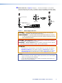
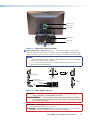
Figure 1. TLP 1000MV Application Diagram
Configurable red and green status LEDs — provide feedback about various user-defined
system states, including room availability.
Automatic clock synchronization with the controller — provides accurate time and date
display.
Multiple mounting options
• The TLP 1000MV can be mounted in a rack (with optional kit), wall, lectern, or any flat
surface.
• The TLP 1000TV comes with a weighted base that allows up to 45° of tilt. It can stand on a
tabletop, be swivel mounted (with optional kit), or installed on a VESA mount (with optional
kit).
Kensington lock support (TLP 1000TV only) — allows the to be locked to a table or other flat
surface, for additional security.
TLP 1000MV and TLP 1000TV • Introduction 2

Requirements
Software
For a complete list of the requirements for running GlobalConfigurator 3 or GUIConfigurator, see
the Extron web page for that software.
NOTE: These touchpanels and controllers are not compatible with GUI Designer or Global
Configurator Plus and Global Configurator Professional.
Hardware
An Extron IP Link control interface must also be connected to the same network domain as the
TouchLink panel. See www.extron.com for a list of suitable controllers.
NOTE: These touchpanels and controllers are not compatible with the Extron Pro series of
devices.
TLP 1000MV and TLP 1000TV • Introduction 3

Panel Features
This section describes:
• TLP 1000MV Front Panel Features
• TLP 1000MV Rear Panel Features and Connections
• TLP 1000TV Front Panel Features and Operations
• TLP 1000TV Rear Panel Features and Connections
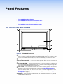
TLP 1000MV Front Panel Features
A
A
A
B
B
B
C
C
C
D
D
D
E
E
E
F
F
F
D
D
D
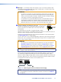
Figure 2. TLP 1000MV Front Panel
A
Motion sensor — is capped with a small Fresnel lens that focuses light onto the sensor.
When no motion has been detected for a user-defined period of time, the unit enters sleep
mode. When motion is detected by the sensor, the screen display is restored and active.
B
Microphone — is located below the LCD screen.
C
Connection status LED — is unlit during normal operation. Blinks red if the connection to
the IP Link controller is lost.
D
Configurable LEDs — (two) are on the top corners of the panel and can be configured by
the user to provide information about the system. The LEDs can be configured to light red or
green and have two rates (blinking and always on).
E
LCD screen — has a 1024x600 resolution with a touch overlay. A graphical user interface,
designed using the Extron GUI Configurator software (see Using GUI Configurator on
page 30), displays buttons, text, or icons on the screen. These are configured for a range
of user-defined functions, using the Extron Global Configurator software (see Using Global
Configurator on page 36).
F
Speakers — (two) are located under the screen, on either side of the panel. They provide
audible feedback for the user.
TLP 1000MV and TLP 1000TV • Panel Features 4

A
A
A
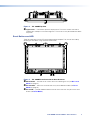
Figure 3. TLP 1000MV Top View
A
Light sensor — mounted on top of the display frame. The sensor monitors the level of
ambient light and adjusts the screen brightness. The sensor can only be viewed from above
the panel.
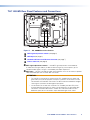
Reset Buttons and LED
There are two buttons and an LED recessed behind the faceplate. They can be accessed by
removing the front bezel, using the Extron removal tool.
A
A
AC
C
CB
B
B
Figure 4. TLP 1000MV Front Panel with the Bezel Removed
A
Menu button — activates the on-screen menus for calibrating the unit (see On-screen
Menus on page 16).
B
Reset button — allows the unit to be reset in any of four different modes (see Reset
Modes on page 49).
C
Reset LED — provides feedback about the reset status when the user presses the reset
button (see Reset Modes).
figure 4
TLP 1000MV and TLP 1000TV • Panel Features 5

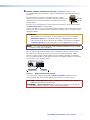
TLP 1000MV Rear Panel Features and Connections
A
A
AC
C
CB
B
B D
D
D
Figure 5. TLP 1000MV Rear Panel Features
A
MTP signal adjustment controls (see page 6)
B
MTP input (see page 6)
C
Network and Power over Ethernet connector (see page 7)
D
Power connector (see page 9)
A
MTP signal adjustment controls — three MTP signal adjustments are available for
S-video luminance gain (VID/Y), S-video chrominance gain (C), and sharpness (S). For
composite video signals, the gain is controlled by the VID/Y adjustment.
B
MTP input — connect a twisted pair cable, terminated with an RJ-45 connector, to provide
video and audio input from an Extron MTP transmitter.
ATTENTION:
• The right RJ-45 connector on the back of the TLP 1000MV (with the yellow and
green LEDs) must be connected to a network. The left RJ-45 connector must be
connected to an Extron MTP Transmitter. The MTP and LAN use different voltages;
switching the connectors will damage the touchpanel.
• Le connecteur RJ-45 droit situé au dos du TLP 1000MV (avec des LED jaunes
et vertes) doit être connecté à un réseau. Le connecteur RJ-45 gauche doit être
connecté à un émetteur MTP Extron. Le MTP et le LAN utilisent des tensions
différentes; permuter les connections risque d’endommager l’écran tactile.
figure 5
MTP signal adjustment controls
MTP input
TLP 1000MV and TLP 1000TV • Panel Features 6

C
Network and Power over Ethernet connector (see figure 5 on page 6) — the
TLP1000MV connects to a network using a twisted pair cable, terminated with an RJ-45
connector.
The network port has two LEDs. The green LED lights solid to
indicate that the touchpanel is connected correctly to a network. The
yellow LED flashes to indicate that data is being passed to or from
the touchpanel.
An Extron IP Link control processor must also be connected to the same network domain
(see www.extron.com for suitable models).
The TLP 1000MV can use a 12 VDC desktop power supply and is also Power over Ethernet
(PoE 802.3af, class3) compliant. Extron recommends using the XTP PI 100 power injector
(see figure 6 below).
ATTENTION:
• Do not power on the touchpanels or control processors until you have read the
Attention on page 10 (12 VDC power supply) or on page 8 (power injector).
• Ne branchez pas les écrans tactiles ou les contrôleurs avant d’avoir lu les mises
en garde page 10 (source d’alimentation 12VCC) ou page 8 (injecteur PoE).
NOTE: If a 12 VDC and a PoE power supply are both connected to the TLP1000MV,
the power injector takes precedence.
Use a straight-through Ethernet cable to connect the power supply to a switch or router.
This cable carries network information from the switch or router to the power supply.
Connect a second straight-through cable to carry the network information and power to
the TLP 1000MV. Connect the IEC power cord from the PoE power supply to a convenient
100-240 VAC, 50-60 Hz power source.
100-240V
~
50-60Hz
0.4A MAX
XTP
PWR
XTP PWR
To network switchTo touchpanel
Figure 6. Connecting the Power Injector
If a 12 VDC power supply is being used (see Power connector on page 9) run one
straight-through cable from the LAN/PoE connector directly to a switch or router.
CAUTION: Risk of Explosion if battery is replaced by an incorrect type. Dispose of
used batteries according to the instructions.
ATTENTION
: Risque d’explosion. Ne pas remplacer la pile par le mauvais type de
pile. Débarrassez-vous des piles utilisées selon le mode d’emploi.
Network and Power over Ethernet connector
LAN/PoE
Link LED
Activity LED
RJ-45 Po
rt
TLP 1000MV and TLP 1000TV • Panel Features 7

ATTENTION:
• The touchpanels are intended for connection to a Power over Ethernet circuit for intra-
building use only and are considered to be part of a Network Environment 0 per IEC
TR62101.
• Les écrans tactiles sont conçu pour une connexion à un circuit PoE pour une utilisation
intérieure seulement et est considéré comme faisant partie d’un environnement réseau
0 par IECTR62101.
• Always use a power supply provided by or specified by Extron. Use of an unauthorized
power supply voids all regulatory compliance certification and may cause damage to
the supply and the end product.
• Utilisez toujours une source d’alimentation fournie ou recommandée par Extron.
L’utilisation d’une source d’alimentation non autorisée annule toute conformité
réglementaire et peut endommager la source d’alimentation ainsi que le produit final.
• These products are intended for use with a UL Listed power source marked “Class2”
or “LPS” and rated 12VDC, minimum 1.0 A or 48 VDC (PoE), minimum 0.35 A.
• Ces produits sont destiné à une utilisation avec une source d’alimentation listéeUL
avec l’appellation «Classe2» ou «LPS» et normée 12Vcc, 1,0A minimum ou 48Vcc
(PoE), 0,35A minimum.
• Extron power supplies are certified to UL/CSA 60950-1 and are classified as LPS
(Limited Power Source). Use of a non-LPS or unlisted power supply will void all
regulatory compliance certification.
• Les sources d’alimentation Extron sont qualifiées UL/CSA60950-1 et sont
classéesLPS(LimitedPowerSource). L’utilisation d’une source d’alimentation non-
listée ou non-listéeLPS annulera toute certification de conformité réglementaire.
• Unless otherwise stated, the AC/DC adapters are not suitable for use in air handling
spaces or in wall cavities. The power supply is to be located within the same vicinity
as the Extron AV processing equipment in an ordinary location, Pollution Degree 2,
secured to the equipment rack within the dedicated closet, podium, or desk.
• Sauf mention contraire, les adaptateurs AC/DC ne sont pas appropriés pour une
utilisation dans les espaces d’aération ou dans les cavités murales. La source
d’alimentation doit être située à proximité de l’équipement de traitement audiovisuel
dans un endroit ordinaire, avec un degré2 de pollution, fixé à un équipement de rack à
l’intérieur d’un placard, d’une estrade, ou d’un bureau.
• Power over Ethernet (PoE) is intended for indoor use only. It is to be connected only to
networks or circuits that are not routed to the outside plant or building.
• L’alimentation via Ethernet (PoE) est destinée à une utilisation en intérieur uniquement.
Elle doit être connectée seulement à des réseaux ou des circuits qui ne sont pas routés
au réseau ou au bâtiment extérieur.
• The installation must always be in accordance with the applicable provisions of National
Electrical Code ANSI/NFPA 70, article 725 and the Canadian Electrical Code part 1,
section 16.
• Cette installation doit toujours être en accord avec les mesures qui s’applique au
National Electrical Code ANSI/NFPA70, article725, et au Canadian Electrical Code,
partie1, section16.
• The power supply shall not be permanently fixed to building structure or similar
structure.
• La source d’alimentation ne devra pas être fixée de façon permanente à une structure
de bâtiment ou à une structure similaire.
page 8
TLP 1000MV and TLP 1000TV • Panel Features 8

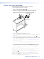
D
Power connector (see figure 5 on page 6) — connect the two pole, 3.5 mm captive
screw connector from the 12 VDC, 1.0 A power supply (not provided) to the power supply
socket on the rear panel. Ensure the connections have the correct polarity as shown below.
Power Receptacle
DC Power Cord
Captive Screw Connector
SECTION A–A
Ridges
Smooth
Power Supply
Output Cord
AA
3/16"
(5 mm) Max.
External Power Supply
(12 VDC, 1.0 A max.)
Ground all
Devices
Ground
+12 VDC input
G
Figure 7. Power Supply Connection
WARNING: The two power cord wires must be kept separate while the power
supply is plugged in. Remove power before wiring.
AVERTISSEMENT : Les deux cordons d’alimentation doivent être tenus à l’écart
l’un de l’autre quand l’alimentation est branchée. Couper l’alimentation avant de
faire l’installation électrique.
CAUTION: Risk of Explosion if battery is replaced by an incorrect type. Dispose of
used batteries according to the instructions.
ATTENTION
: Risque d’explosion. Ne pas remplacer la pile par le mauvais type de
pile. Débarrassez-vous des piles utilisées selon le mode d’emploi.
ATTENTION:
• Do not power on the touchpanels or control processors until you have read the
Attention on page 10 (12 VDC power supply) or on page 8 (power injector).
• Ne branchez pas les écrans tactiles ou les contrôleurs avant d’avoir lu les mises
en garde page 10 (source d’alimentation 12VCC) ou page 8 (injecteur PoE).
NOTES:
• These touchpanels ship with a power injector. If you wish to use a 12 VDC power
supply it must be purchased separately.
• If a 12 VDC and a PoE power supply are both connected to the touchpanel, the
power injector takes precedence.
Power connector
TLP 1000MV and TLP 1000TV • Panel Features 9

ATTENTION:
• Always use a power supply provided by or specified by Extron. Use of an unauthorized
power supply voids all regulatory compliance certification and may cause damage to
the supply and the end product.
• Utilisez toujours une source d’alimentation fournie ou recommandée par Extron.
L’utilisation d’une source d’alimentation non autorisée annule toute conformité
réglementaire et peut endommager la source d’alimentation ainsi que le produit final.
• This product is intended for use with a UL Listed power source marked “Class 2” or
“LPS” and rated 12VDC, minimum 1.0 A or 48 VDC (PoE), minimum 0.35 A.
• Ce produit est destiné à une utilisation avec une source d’alimentation listéeUL avec
l’appellation «Classe2» ou «LPS» et normée 12Vcc, 1,0A minimum ou 48Vcc
(PoE), 0,35A minimum.
• Extron power supplies are certified to UL/CSA 60950-1 and are classified as LPS
(Limited Power Source). Use of a non-LPS or unlisted power supply will void all
regulatory compliance certification.
• Les sources d’alimentation Extron sont qualifiées UL/CSA60950-1 et sont
classéesLPS(LimitedPowerSource). L’utilisation d’une source d’alimentation non-
listée ou non-listéeLPS annulera toute certification de conformité réglementaire.
• Unless otherwise stated, the AC/DC adapters are not suitable for use in air handling
spaces or in wall cavities. The power supply is to be located within the same vicinity as
the Extron AV processing equipment in an ordinary location, Pollution Degree 2, secured
to the equipment rack within the dedicated closet, podium, or desk.
• Sauf mention contraire, les adaptateurs AC/DC ne sont pas appropriés pour une
utilisation dans les espaces d’aération ou dans les cavités murales. La source
d’alimentation doit être située à proximité de l’équipement de traitement audiovisuel
dans un endroit ordinaire, avec un degré2 de pollution, fixé à un équipement de rack à
l’intérieur d’un placard, d’une estrade, ou d’un bureau.
• The installation must always be in accordance with the applicable provisions of National
Electrical Code ANSI/NFPA 70, article 725 and the Canadian Electrical Code part 1,
section 16. The power supply shall not be permanently fixed to building structure or
similar structure.
• Cette installation doit toujours être en accord avec les mesures qui s’applique au
National Electrical Code ANSI/NFPA70, article725, et au Canadian Electrical Code,
partie1, section16. La source d’alimentation ne devra pas être fixée de façon
permanente à une structure de bâtiment ou à une structure similaire.
• The length of the exposed wires in the stripping process is critical. The ideal length is
3/16 inches (5 mm). Any longer and the exposed wires may touch, causing a short
circuit between them. Any shorter and the wires can be easily pulled out even if tightly
fastened by the captive screws.
• La longueur des câbles exposés est primordiale lorsque l’on entreprend de les dénuder.
La longueur idéale est de 5mm (3/16inches). S’ils sont un peu plus longs, les câbles
exposés pourraient se toucher et provoquer un court circuit. S’ils sont un peu plus
courts, ils pourraient sortir, même s’ils sont attachés par les vis captives.
• Do not tin the wire leads before installing into the connector. Tinned wires are not as
secure in the connector and could be pulled out.
• Ne pas étamer les conducteurs avant de les insérer dans le connecteur. Les câbles
étamés ne sont pas aussi bien fixés dans le connecteur et pourraient être retirés.
Attention on page 10
mises en garde page 10
TLP 1000MV and TLP 1000TV • Panel Features 10

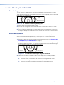
TLP 1000TV Front Panel Features and Operations
A
A
A
B
B
BC
C
C
D
D
D
D
D
D
E
E
E
F
F
F
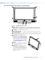
Figure 8. TLP 1000TV Front Panel Features
A
Motion sensor — is capped with a small Fresnel lens that focuses light onto the sensor.
When no motion has been detected for a user-defined period of time, the unit enters sleep
mode. When motion is detected by the sensor, the screen display is restored and active.
B
Microphone — is located below the LCD screen.
C
Connection status LED — is unlit during normal operation. Blinks red if the connection to
the IP Link controller is lost.
D
Configurable LEDs (2) — on the top corners of the panel can be configured by the user to
provide information about the system. The LEDs can be configured to light red or green and
have two rates (blinking and always on).
E
LCD screen — has a 1024x600 resolution
with a touch overlay. A graphical user interface,
designed using the Extron GUI Configurator
software (see page 26), displays buttons, text,
or icons on the screen. These are configured
for a range of user-defined functions, using the
Extron Global Configurator software (see
page31).
F
Speakers — two speakers located under the
screen, on either side of the panel, provide
audible feedback for the user.
G
Light sensor — (see the figure to the right)
mounted on top of the display frame. The
sensor monitors the level of ambient light and
adjusts the screen brightness and button
backlighting. The sensor can only be viewed
from above the panel.
G
G
G
TLP 1000MV and TLP 1000TV • Panel Features 11

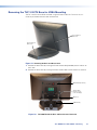
TLP 1000TV Rear Panel Features and Connections
The TLP 1000TV has a stand that allows it to be placed on a desktop. The stand can be
removed to VESA mount the unit. Both the stand and the touchpanel have removable covers
that conceal the rear panel features and protect cables that are attached to the TLP1000TV.
The rear and base covers can be removed using the Extron removal tool (see Removing the
TLP 1000TV Base for VESA Mounting on page 47).
D
D
D
E
E
E
F
F
F
A
A
A
B
B
B
C
C
C
G
G
G
H
H
H
I
I
I
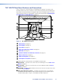
Figure 9. TLP 1000TV Rear Features
A
Menu button (see page 12)
B
Reset button (see page 12)
C
Reset LED (see page 12)
D
MTP signal adjustment controls (see page 12)
E
MTP input (see page 13)
F
Network and Power over Ethernet connector (see page 13)
G
Power connector (see page 14)
H
VESA mounting holes (see page 15)
I
Kensington Security Slot (see page 15)
The following features and connections are available on the back panel.
A
Menu button — activates the on-screen menus for calibrating the unit (see On-screen
Menus on page 16).
B
Reset button — allows the unit to be reset in any of four different modes (see Reset
Modes on page 49).
C
Reset LED — provides feedback about the reset status when the user presses the reset
button (see Reset Modes).
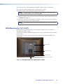
D
MTP signal adjustment controls — three MTP signal adjustments are available for
S-video luminance gain (VID/Y), S-video chrominance gain (C), and sharpness (S). For
composite video signals, the gain is controlled by the VID/Y adjustment.
figure 9
Menu button
Reset button
Reset LED
MTP signal adjustment controls
TLP 1000MV and TLP 1000TV • Panel Features 12
La page est en cours de chargement...
La page est en cours de chargement...
La page est en cours de chargement...
La page est en cours de chargement...
La page est en cours de chargement...
La page est en cours de chargement...
La page est en cours de chargement...
La page est en cours de chargement...
La page est en cours de chargement...
La page est en cours de chargement...
La page est en cours de chargement...
La page est en cours de chargement...
La page est en cours de chargement...
La page est en cours de chargement...
La page est en cours de chargement...
La page est en cours de chargement...
La page est en cours de chargement...
La page est en cours de chargement...
La page est en cours de chargement...
La page est en cours de chargement...
La page est en cours de chargement...
La page est en cours de chargement...
La page est en cours de chargement...
La page est en cours de chargement...
La page est en cours de chargement...
La page est en cours de chargement...
La page est en cours de chargement...
La page est en cours de chargement...
La page est en cours de chargement...
La page est en cours de chargement...
La page est en cours de chargement...
La page est en cours de chargement...
La page est en cours de chargement...
La page est en cours de chargement...
La page est en cours de chargement...
La page est en cours de chargement...
La page est en cours de chargement...
La page est en cours de chargement...
La page est en cours de chargement...
La page est en cours de chargement...
-
 1
1
-
 2
2
-
 3
3
-
 4
4
-
 5
5
-
 6
6
-
 7
7
-
 8
8
-
 9
9
-
 10
10
-
 11
11
-
 12
12
-
 13
13
-
 14
14
-
 15
15
-
 16
16
-
 17
17
-
 18
18
-
 19
19
-
 20
20
-
 21
21
-
 22
22
-
 23
23
-
 24
24
-
 25
25
-
 26
26
-
 27
27
-
 28
28
-
 29
29
-
 30
30
-
 31
31
-
 32
32
-
 33
33
-
 34
34
-
 35
35
-
 36
36
-
 37
37
-
 38
38
-
 39
39
-
 40
40
-
 41
41
-
 42
42
-
 43
43
-
 44
44
-
 45
45
-
 46
46
-
 47
47
-
 48
48
-
 49
49
-
 50
50
-
 51
51
-
 52
52
-
 53
53
-
 54
54
-
 55
55
-
 56
56
-
 57
57
-
 58
58
-
 59
59
-
 60
60


dans d''autres langues
- English: Extron TLP 1000TV User manual
Documents connexes
-
Extron TLP 710TV Manuel utilisateur
-
Extron TLP 1000MV Manuel utilisateur
-
-
Extron TLP Pro 320M Manuel utilisateur
-
-
Extron TLP Pro 525T Manuel utilisateur
-
Extron TLP 700MV Manuel utilisateur
-
Extron TouchLink TLP Pro 725C Series Manuel utilisateur
-
-
Extron TLP Pro 1022M Manuel utilisateur