
© 2019 Agnetix Inc. All Rights Reserved. Specifications subject to change
7965 Dunbrook Road - Suite I - San Diego, CA 92126
1
agnetix.com
Agnetix
Product Guide – Specifications & Installation
Agnetix A3 1200
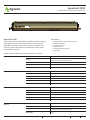
Agnetix A3 1200
The Agnetix Liquid-Cooled Intelligent LED Horticulture System
is designed for greater operational efficiency and improved
yields. By leveraging our innovative platform, customers can
positively impact their bottom line with higher output, lower
costs and better quality.
Please read and understand these installation instructions.
Key Features
• Highly-Efficient, Liquid Cooled System
• Simple Installation
• Low Maintenance
• High Powered
• Suitable for Wet Locations
• ETL Listed
PRODUCT SPECIFICATIONS
Power 1200W
Efficacy
2.23 µmol/J (A3 - Standard Density)
2
.45 µmol/J (A3 - DD Double Density)
Spectrum White (5000K) + 660nm Red (others by request)
Beam Angle 120º
Cooling Twin 1/2” Copper Tubes (1-3gpm/tube)
PHYSICAL
Housing Aluminum Extrusion
Dimensions 36” x 4” x 5”
Tube Length 40”
Weight 15 Lbs
Mounting Through bolts on Light Spine (Bolts not included)
Lens Injection molded plastic
POWER
Voltage 180-300 VAC
Current 5 Amps max
Power 1200W (Wattage reduced under 240V)
PF >0.95
Frequency 50/60 Hz (Generator compatible)
Connector Male 3-pin industrial type, UL2237
OPTICAL
Modules 3
LEDs 5000K + 660nm
Efficacy
2
.
23 µmol/J (A3 - Standard Density)
2
.45 µmol/J (A3 - DD Double Density)
Beam Angle 120º
¨
AgnetixÊA3-1200-001Ê0717
Suitable for W
e
t
Locations
Convient Aux Emplacements Mouilles
180V
-
2
50VÊ5AÊMaxÊorÊ277VÊ1265WÊMax

© 2019 Agnetix Inc. All Rights Reserved. Specifications subject to change
7965 Dunbrook Road - Suite I - San Diego, CA 92126
2
agnetix.com
Agnetix
Product Guide – Specifications & Installation
Agnetix A3 1200
CONTROL Network 4 x 100Mb POE Ethernet
Connectors 4 x Waterproof 13/16 RJ45
Dimming Down to 1%
ENVIRONMENTAL Operating Conditions -20°C(-4ºF) to 60°C (140ºF)/ RH <95%
Storage Conditions (no liquid) -20°C(-4ºF) to 80°C (176ºF) / RH <95
IP IP66 Wash Down
WATER LOOP/COOLING
*Protect From Freezing - or - Use Antifreeze
Fluid Temperature Limits -20°C(-4ºF) – 75°C (167ºF )
Fluid Temperature Recommended Dew point up to 40°C (104ºF)
Self Protection 65°C (149°F) (full light) to 75°C (167°F) (no light)
Max Fluid Temp when using light for Heat 75°C (167°F)
Fluid Connection Twin Exposed 1/2” Copper Tubing
Push to Connect
Do not solder or crimp
Flow Rate 1 to 3 gpm per tube
Temp Rise Depends on flow rate
Power Delivered to Water ~600W
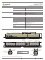
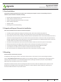
DIMENSIONS (INCHES)
*LED Module for A3-1200-DD contain different LED pattern with twice the LED count
Light Spine mounting system
5.0
.25
.25
3
8
x
7
8
3.7
2.0
2.0
3.33 Nominal
40 Nominal
36.5
5.12
14.0
2.0
Downward USB
Port #1
RJ-45 Ethernet
Network Port
w/ POE
RJ-45 Ethernet
Network Port
w/ POE
USB
Port #2
7
8 Power Cable System
Connection
LED Module #2
LED Module #1
LED Module #3
RJ-45 Ethernet
Network Port
w/ POE
1
2" Copper Tubing
Do Not Solder or Crimp
*

© 2019 Agnetix Inc. All Rights Reserved. Specifications subject to change
7965 Dunbrook Road - Suite I - San Diego, CA 92126
3
agnetix.com
Agnetix
Product Guide – Specifications & Installation
Agnetix A3 1200
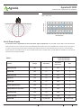
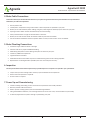
BEAM ANGLE = 120º SPECTRAL DISTRIBUTION
White + 660nm Red
Wavelength (nm)
1
0.9
0.8
0.7
0.6
0.5
0.4
0.3
0.2
0.1
0
Relative Intensity
350 400 450 500 550 600 650 700 750 800
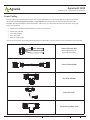
Verify Power Supply
TABLE 1
It is the owner/user’s responsibility to ensure the power supply is appropriate. The A3-1200 requires 208 to 277V 50/60Hz AC
power. Various services can be used. Consult the following table to determine the acceptability of the power source. Connection
to a source in excess of 277V will cause immediate fixture destruction and is not covered by the warranty. It is recommended
(and usually most cost effective) to use a step up/down transformer if needed, and to provide 480Y/277 3P 5W service to operate
the fixture at 277V where possible.
6 Units per 30A cable
3 units per 15A cable
Standard Voltage Connection
Max Watts
(LED Power)
Amps
208Y/120 3P 5W 208 L-L 925 5
208Δ 3P 4W 208 L-L 925 5
380Y/220 3P 5W 220 L-N 985 5
240/120 1P 240 L-L 1085 5
240Δ 3P 4W 240 L-L 1085 5
240Δ 3P 5W Split Phase 240 L-L 1085 5
240Δ 3P 4W Corner Grounded 240 L-L 1085 5
415Y/240 3P 5W 240 L-N 1085 5
480Y/277 3P 5W 277 L-N 1200 4.7
480Δ 3P 4W 480 DO NOT USE DO NOT USE DO NOT USE

© 2019 Agnetix Inc. All Rights Reserved. Specifications subject to change
7965 Dunbrook Road - Suite I - San Diego, CA 92126
4
agnetix.com
Agnetix
Product Guide – Specifications & Installation
Agnetix A3 1200
Owner / User Responsibilities
Planning
It is the responsibility of the engineer, contractor, installer, purchaser, owner, and user to design the mechanical electrical and
plumbing systems, install, maintain, and operate the fixtures in such a manner as to comply with all applicable codes, state and
local laws, ordinances, and regulations. Consult with the appropriate inspector to ensure compliance.
Agnetix case studies, plan examples, and suggestions are not ready-to-submit plans, and are only intended to educate and inform
a qualified person to develop the best plan for your facility.
• The number and type of fixtures, power requirements, cost and complexity of your plan and facility will depend on your
growth style and lighting requirements.
• The end user should consider utility incentives which may offset the cost of Agnetix fixtures.
• Consult the Facility Planning Guide for detailed planning instructions. These instructions are not a substitute for qualified
engineering services.
• Create an industrial horticultural lighting plan that identifies and locates all fixtures, plumbing runs, and cable runs. Use this
Product and Installation Guide and qualified engineering services to determine and produce the proper plan for your facility.
The basic procedure is recommended to produce an appropriate plan:
1. Determine your desired PPFD and lighted area for your chamber.
2. Determine room dimensions and canopy dimensions.
3. Calculate the required number of fixtures (N = PPFD * Area (m²)/ Fixture PPF).
4. Choose the desired row and column spacing and the physical layout of your facility.
5. Layout the fixtures as desired, and check that they fit reasonably well. Adjust the spacing as necessary. Note that higher
efficacy fixtures have larger spacing at equal PPFD.
6. Set fixture height above canopy at half of row spacing or higher, and verify it is acceptable.
7. Calculate total power and verify availability of supply.
a. For a retrofit or with traditional HVAC, assume PFACILITY = 1.5 * PLIGHTS
b. For a full hydronic system, assume PFACILITY = 1.25 * PLIGHTS
c. Systems which operate on a 12hr/12hr flip may use as little as half of this power
8. Your engineering professional should use this information to generate a plan for the rest of the system including:
a. Cooling method (Tower, ground source, etc)
b. HVAC (if used)
c. Electrical system
d. Plumbing system
9. Calculate the total cooling loop load.
a. For retrofit, or traditional HVAC systems PLOOP = 0.5 * PLIGHTS (0.4 for DE fixtures)
b. For a full hydronic system, PLOOP can be estimated as PLOOP = PFACILITY
c. Take into account 12hr/12hr flip
10. Determine the parts list per row. www.agnetix.com website includes examples which may be helpful.
a. Consider appropriate check valves and ball valves sufficient for isolation of plumbing loops.
REMINDER: Proper handling and maintenance of the cooling loop is required to maintain fixture performance.

© 2019 Agnetix Inc. All Rights Reserved. Specifications subject to change
7965 Dunbrook Road - Suite I - San Diego, CA 92126
5
agnetix.com
Agnetix
Product Guide – Specifications & Installation
Agnetix A3 1200
1. Start Installation
Verify that all supporting equipment is in place. This includes physical support, electrical, and plumbing. Ensure all
additional parts and tools are available, including:
• Brackets and mounting hardware as specified on your plan
• Safety tether if required in your area
• Tools for attaching brackets and hardware as needed
• Power Cabling components
• Network cables
• Plumbing parts and specified tubing
2. Unpack and Prepare Fixtures for Installation
Note: The installation process requires a minimum of 2 people.
• Carefully inspect the boxes for damage or loss during transit. Each carton contains two (2) fixtures.
• Cover your work surface with a towel or other soft material to prevent scratching the fixtures and lenses.
• Open the box and remove the top packing materials. Place these upside down on your work surface. Remove the fixture
and place into the packing materials on your work surface. Inspect the fixture, connectors, lenses and copper tubes for
damage. Small deformations of the tubes may be corrected with the gentle use of a tubing expander. Do not remove the
protective film from the lenses until commissioning in Step 7.
• If brackets are specified in your plan, attach them to the fixtures while the protective supports are still in place.
• Remove the protective end support and one fixture, while a second person supports the second unit.
• The protective end support should be replaced if the second unit will not be immediately installed.
• Lay the fixture on its side on your work surface, and inspect the fixture for damage.
• Do not rest the fixture on the high transmission lens. They may be easily scratched or cracked.
3. Mounting
Mount the fixture as directed in your plan.
The Light Spine mounting rail contains ¼ inch holes as well as 3/8 x 1/2 inch slots on an inch referenced grid spaced as
shown in A3-1200 Basic Dimensions diagram. Bolts of ¼ inch and larger diameter are appropriate for mounting the fixture.
Locknuts and/or lock washers are recommended. Maintain fixture spacing as directed in your plan. It may be helpful to
tighten bolts after plumbing connections are completed.
Follow all local codes and safety rules for mounting of the fixtures. A safety cable (not supplied) may be required in some
jurisdictions. The middle slot can accommodate such a device. It may be helpful to mount brackets for mounting or for
accessories while the fixture is on your work surface.

© 2019 Agnetix Inc. All Rights Reserved. Specifications subject to change
7965 Dunbrook Road - Suite I - San Diego, CA 92126
6
agnetix.com
Agnetix
Product Guide – Specifications & Installation
Agnetix A3 1200
5. Make Plumbing Connections
• Check the copper tubes for dents or damage.
• Measure and cut any required additional tubing.
• Slide tubing and push to connect fittings into place as shown on your plan.
• Install any additional components.
• Tighten brackets if needed
• Small deformations of the tubes may be corrected with the gentle use of a tubing expander.
• Replacement of a damaged tube is possible, but is not covered by the warranty.
7. Power Up and Commissioning
• Install remaining networking, sensors and control components if not already installed.
• Remove protective film from lenses.
• Power up water cooling system, fixtures and networking hardware.
• Using the dashboard software, sort and assign fixtures to the correct room, row and column of your facility.
• If directed, adjust the user power settings as specified by your plan.
6. Inspection
Do not operate the fixtures before inspection by a qualified person or inspector as required in your jurisdiction.
• Inspect the system for damage and to ensure proper installation of all components.
• Perform formal inspection as required.
• Pressure test as required.
4. Make Cable Connections
Follow the cable layout and installation details on your plan. The general information presented here is only intended to
familiarize you with the components.
• Ensure power is off.
• Install power receptacles at the junction boxes or electrical panels as specified in your plan.
• Route, secure and install the power cabling, using tees, cable segments and drop taps as shown on your plan.
• Spacing to other cables must be maintained to prevent overheating.
• Verify all connections are tight to maintain water resistance.
• Route, secure and connect the RJ-45 network cables to your fixtures and hub.
• For wet location installations ensure only IP67 cables are used, or that an outer cover is installed.

© 2019 Agnetix Inc. All Rights Reserved. Specifications subject to change
7965 Dunbrook Road - Suite I - San Diego, CA 92126
7
agnetix.com
Agnetix
Product Guide – Specifications & Installation
Agnetix A3 1200
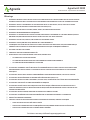
Power Cabling
A power cable is not supplied with the fixture. For retrofit applications, an unterminated cable of the appropriate length
may be ordered. Contact Agnetix for details. The A3-1200 utilizes a UL2237 Multi-point Interconnection Power Cable
Assemblies for Industrial Machinery, PVVA listed power cable system, to reduce the time and expense of power wiring. The
system is composed of:
• Outlets (15A and 30A) (to be installed by your electrical contractor)
• Cables (15A and 30A)
• Tees (15A and 30A)
• Drop Tees (15A)
• Reducers (30A to 15A)
At 277V, up to 6 fixtures can generally be operated from one 30A cable, or up to 3 fixtures can be operated from one 15A cable.
Outlets (15A and 30A)
(to be installed by your
electrical contractor)
Cables (15A and 30A)
Tees (15A and 30A)
Drop Tees (15A)
Tee-Reducing (30A to 15A)

© 2019 Agnetix Inc. All Rights Reserved. Specifications subject to change
7965 Dunbrook Road - Suite I - San Diego, CA 92126
8
agnetix.com
Agnetix
Product Guide – Specifications & Installation
Agnetix A3 1200
Warnings
◊ WARNING: PRODUCT MUST BE I
NSTALLED IN ACCORDANCE WITH THE APPLICABLE INSTALLATION CODE BY
A PERSON FAMILIAR WITH CONSTRUCTION AND OPERATION OF PRODUCT AND THE HAZARDS INVOLVED.
◊ WARNING: INSTALL THE PRODUCT IN ACCORDANCE WITH ALL NATIONAL, STATE, AND LOCAL CODES.
◊ WARNING: DO NOT EXCEED FIXTURE SPECIFIED VOLTAGE (277V).
◊ WARNING: DO NOT USE IF FIXTURE, LENSES, PARTS, OR CABLES ARE DAMAGED.
◊ WARNING: PROPER GROUNDING IS REQUIRED.
◊ WARNING: TO AVOID ELECTRIC SHOCK HAZARD, DISCONNECT THE POWER AT THE PANEL BOARD (CIRCUIT
BREAKER BOX) BEFORE BEGINNING INSTALLATION. DO NOT HOT SWAP FIXTURES.
◊ WARNING: DO NOT CUT, MODIFY, OR SOLDER TO THE COPPER TUBES.
◊ WARNING: UNAUTHORIZED FIELD REPAIRS WILL VOID WARRANTY.
◊ CE PRODUIT DOIT ÊTRE INSTALLÉ SELON LE CODE D’INSTALLATION PERTINENT, PAR UNE PERSONNE QUI
CONNAÎT BIEN LE PRODUIT ET SON FONCTIONNEMENT AINSI QUE LES RISQUES INHÉRENTS.
◊ SUITABLE FOR WET LOCATIONS.
◊ CONVIENT AUX EMPLACEMENTS MOUILLÉS
◊ WHEN INSTALLING IN WET OR DAMP LOCATIONS, ENSURE THAT:
• ALL PORTS NOT IN USE ARE CAPPED
• ALL CONNECTIONS ARE MADE WITH WATERPROOF CONNECTORS OR BOOTS
• ALL CONNECTIONS ARE PROPERLY TIGHTENED
◊ ATTENTION: LE PRODUIT DOIT ÊTRE INSTALLÉ CONFORMÉMENT AU CODE D'INSTALLATION APPLICABLE
UNE PERSONNE FAMILIALE AVEC LA CONSTRUCTION ET L'EXPLOITATION DE PRODUIT ET LES DANGERS
IMPLIQUES.
◊ ATTENTION: INSTALLER LE PRODUIT CONFORMÉMENT AUX CODES NATIONAUX, LOCAUX ET LOCAUX.
◊ ATTENTION: NE PAS DÉPASSER LA TENSION SPÉCIFIÉE PAR FIXATION (277V).
◊ ATTENTION: NE PAS UTILISER SI L'APPAREIL, LES LENTILLES, LES PIÈCES OU LES CÂBLES SONT ENDOMMAGÉS.
◊ ATTENTION: UNE MISE À LA TERRE APPROPRIÉE EST REQUISE.
◊ ATTENTION: POUR ÉVITER TOUT RISQUE DE CHOC ÉLECTRIQUE, DÉBRANCHEZ L'ALIMENTATION DE LA
CARTE DU PANNEAU (CIRCUIT BOITE DE DISJONCTEUR) AVANT DE COMMENCER L'INSTALLATION. NE PAS
CHAUD FIXTURES SWAP.
◊ ATTENTION: NE PAS COUPER, MODIFIER OU SOUDER LES TUBES EN CUIVRE.
◊ ATTENTION: LES RÉPARATIONS NON AUTORISÉES SUR LE TERRAIN ANNULERONT LA GARANTIE.
◊ ADAPTÉ AUX ENDROITS HUMIDES.
◊ LORS DE L'INSTALLATION DANS DES ENDROITS HUMIDES OU HUMIDES, ASSUREZ-VOUS QUE:
• TOUS LES PORTS NON UTILISÉS SONT CAPPÉS
• TOUTES LES CONNEXIONS SONT FABRIQUÉES AVEC DES CONNECTEURS OU BOTTES ÉTANCHES
• TOUTES LES CONNEXIONS SONT CORRECTEMENT SERRÉES
•
To initiate a warranty claim email [email protected]
-
 1
1
-
 2
2
-
 3
3
-
 4
4
-
 5
5
-
 6
6
-
 7
7
-
 8
8


dans d''autres langues
- English: Agnetix A3 1200 User manual
Autres documents
-
PHOTONTEK PTEKLED020 Manuel utilisateur
-
 Current Element L2000 Horticulture LED Lighting System Guide d'installation
-
Eti 554221110-4PK Guide d'installation
-
Cooper Lighting Loft WaveStream LED Guide d'installation
-
Cooper Lighting WSL Linear with Wavestream LED technology Guide d'installation
-
 Labconco Protector Echo 181 Series Manuel utilisateur
-
Eaton iLumin Plus Installation Quick Manual
-
Legrand LMFC-011 Dimming Fixture Controller Guide d'installation
-
Wacker Neuson LTW20Z1 Manuel utilisateur
-
Halo ML5612D2W930 Mode d'emploi

