NEC LCD2690WUXI Le manuel du propriétaire
- Catégorie
- Téléviseurs
- Taper
- Le manuel du propriétaire


Index
Warning ..................................................................................................................................................1
Contents ................................................................................................................................................
2
Quick Start ...........................................................................................................................................
3
Controls .................................................................................................................................................
9
Advanced OSM Controls ................................................................................................................... 16
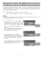
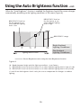
Using the Auto Brightness Function ............................................................................................. 27
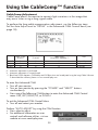
Using the CableComp™ Function ...................................................................................................
29
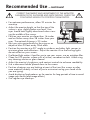
Recommended use ............................................................................................................................30
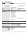
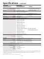
Specifications ................................................................................................................................... 33
Features ..............................................................................................................................................
35
Troubleshooting ................................................................................................................................ 37
References ..........................................................................................................................................
38
Limited Warranty ..............................................................................................................................39
TCO’03 ................................................................................................................................................. 40
Manufacturer’s Recycling and Energy Information .................................................................. 41
Avertissement ...................................................................................................................................
43
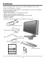
Contenu .............................................................................................................................................. 44
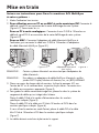
Mise en train ......................................................................................................................................
45
Commandes ........................................................................................................................................ 51
Commandes OSM-Option avancée .................................................................................................
58
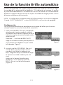
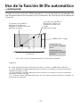
Utilisation de la fonction de luminosité automatique ..............................................................69
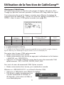
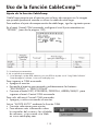
Utilisation de la fonction de CableComp
MD
...................................................................................71
Utilisation recommandée ................................................................................................................ 72
Fiche technique ................................................................................................................................. 75
Fonctions ............................................................................................................................................ 77
Dépannage .......................................................................................................................................... 79
Références ......................................................................................................................................... 80
Garantie limitée ................................................................................................................................
81
TCO’03 ..................................................................................................................................................
82
Informations du fabricant relatives au recylage et aux économies d’énergie ..................83
Advertencia ........................................................................................................................................
85
Contenidos ..........................................................................................................................................
86
Inicio rápido .......................................................................................................................................
87
Controles .............................................................................................................................................93
Controles OSM avanzados ..............................................................................................................100
Uso de la función Brillo automático ............................................................................................. 111
Uso de la función CableComp™ .....................................................................................................113
Uso recomendado ............................................................................................................................ 114
Specifications ................................................................................................................................. 117
Características .................................................................................................................................119
Solución de problemas ....................................................................................................................121
Referencias ....................................................................................................................................... 122
Garantía limitada ............................................................................................................................ 123
TCO’03 ................................................................................................................................................124
Información del fabricante sobre reciclado y energía ........................................................... 125

1
CAUTION: TO REDUCE THE RISK OF ELECTRIC SHOCK, MAKE SURE POWER CORD IS UNPLUGGED FROM
WALL SOCKET. TO FULLY DISENGAGE THE POWER TO THE UNIT, PLEASE DISCONNECT THE POWER
CORD FROM THE AC OUTLET. DO NOT REMOVE COVER (OR BACK). NO USER SERVICEABLE PARTS
INSIDE. REFER SERVICING TO QUALIFIED SERVICE PERSONNEL.
This
symbol warns user that uninsulated voltage within the unit may have sufficient magnitude to
cause electric shock. Therefore, it is dangerous to make any kind of contact with any part inside this
unit.
This symbol alerts the user that important literature concerning the operation and maintenance of this
unit has been included. Therefore, it should be read carefully in order to avoid any problems.
WARNING
CAUTION
Canadian Department of Communications Compliance Statement
DOC: This Class B digital apparatus meets all requirements of the Canadian
Interference-Causing Equipment Regulations.
C-UL: Bears the C-UL Mark and is in compliance with Canadian Safety Regulations
according to
CAN/CSA C22.2 No. 60950-1.
FCC Information
1.
Use the attached specified cables with the
MultiSync LCD2690WUXi
TM
(L266RZ)/
Mul-
tiSync
LCD2490WUXi
TM
(L246T0) color monitor so as not to interfere with radio and
television reception.
(1)
Please use the supplied power cord or equivalent to ensure FCC compliance.
(2) Please use the supplied shielded video signal cable, 15-pin mini D-SUB to
DVI-A cable, DVI-D to DVI-D cable, or D-SUB to D-SUB cable.
Use of other cables and adapters may cause interference with radio and
television reception.
2.
This equipment has been tested and found to comply with the limits for a Class B digital
device, pursuant to part 15 of the FCC Rules. These limits are designed to provide
reasonable protection against harmful interference in a residential installation. This
equipment generates, uses, and can radiate radio frequency energy, and, if not in
-
stalled and used in accordance with the instructions, may cause harmful interference
to radio communications. However, there is no guarantee that interference will not
occur in a particular installation. If this equipment does cause harmful interference to
radio or television reception, which can be determined by turning the equipment off
and on, the user is encouraged to try to correct the interference by one or more of the
following measures:
• Reorient or relocate the receiving antenna.
• Increase the separation between the equipment and receiver.
• Connect the equipment into an outlet on a circuit different from that to which the receiver
is connected.
• Consult your dealer or an experienced radio/TV technician for help.
If necessary, the user should contact the dealer or an experienced radio/television techni
-
cian for additional suggestions. The user may find the following booklet, prepared by
the Federal Communications Commission, helpful: ”How to Identify and Resolve Radio-
TV Interference Problems.“ This booklet is available from the U.S. Government Printing
Office, Washington, D.C., 20402, Stock No. 004-000-00345-4.
TO PREVENT FIRE OR SHOCK HAZARDS, DO NOT EXPOSE THIS UNIT TO RAIN OR MOISTURE. ALSO, DO NOT
USE THIS UNIT’S POLARIZED PLUG WITH AN EXTENSION CORD RECEPTACLE OR OTHER OUTLETS UNLESS THE
PRONGS CAN BE FULLY INSERTED.
REFRAIN FROM OPENING THE CABINET AS THERE ARE HIGH VOLTAGE COMPONENTS INSIDE. REFER SERVIC
-
ING TO QUALIFIED SERVICE PERSONNEL.

2
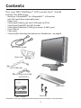
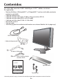
Contents
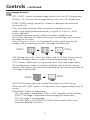
Your new NEC MultiSync
®
LCD monitor box* should
contain the following:
• MultiSync LCD2690WUXi™ or LCD2490WUXi™ LCD monitor
with tilt/swivel/pivot/adjustable stand
• Power Cord
• Video Signal Cable (15-pin mini D-SUB male to DVI-A)
• Video Signal Cable (DVI-D to DVI-D cable)
• Video Signal Cable (mini D-SUB 15 pin to mini D-SUB 15 pin)
• User’s Manual
• Cable cover
• Screws (4) (for mounting the monitor to a flexible arm -
see page 8)
* Remember to save your original box and packing material to transport or ship the monitor.
Power Cord
15-pin mini D-SUB
male to DVI-A
User’s Manual
Cable Cover
DVI-D to DVI-D cable
Screws (4)
Mini D-SUB cable

3
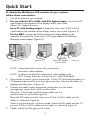
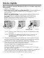
Quick Start
To attach the MultiSync
®
LCD monitor to your system,
follow these instructions:
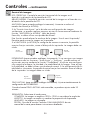
1. Turn off the power to your computer.
2. For use with the PC or MAC with DVI digital output: Connect the DVI
signal cable to the connector of the display card in your system
(Figure A.1). Tighten all screws.
For a PC with Analog output: Connect the 15-pin mini D-SUB to DVI-A
signal cable to the connector of the display card in your system (Figure A.2).
For the MAC: Connect the MultiSync Macintosh cable adapter to the
computer, then attach the 15-pin mini D-SUB signal cable to the MultiSync
Macintosh cable adapter (Figure B.1).
NOTE: Some Macintosh systems do not require a
Macintosh cable adapter.
NOTE: To obtain the MultiSync Macintosh cable adapter call
NEC Display Solutions of America, Inc. (800) 632-4662.
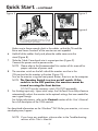
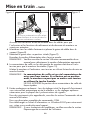
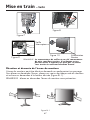
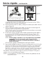
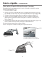
3. Place hands on each side of the monitor. Tilt the LCD panel backwards to a
30-degree angle and lift up to the highest position. Connect all cables to
appropriate connectors (Figure 4).
4. To keep the cables neatly organized, place them into the cable
management system that is built into the stand.
Place the D-Sub cable and the power cable into the
specific hooks as indicated (Figure 5).
Place the DVI cable and the 15-pin mini D-Sub to DVI-A cable into the
hooks as indicated (Figure 6).
When using the monitor in Portrait mode, place the DVI cable and the 15-
pin mini D-Sub to DVI-A cable into the hooks as indicated (Figure 7).
5. Cables should rest flat against the stand.
Figure A.1
Figure A.2
Figure B.1
Macintosh Adapter
(not included)

4
Make sure to leave enough slack in the cables so that the Tilt and the
Raise and Lower functions of the monitor are not impeded.
6. Hold all of the cables firmly and place the cable cover onto the
stand (Figure 8).
7. Slide the Cable Cover back into its correct position (Figure 9).
Connect the power cord to power outlet.
NOTE: Please refer to the Recommended Use section of this manual for
proper selection of power cord.
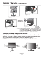
8. The vacation switch on the left side of the monitor must be in the
ON position for the monitor to function (Figure 10).
Turn on the monitor using the front power button, then turn on the computer.
NOTE: The Vacation Switch is a true on/off switch. If this
switch is in the OFF position, the monitor cannot be
turned on using the front button.
DO NOT turn the vacation switch ON/OFF repeatedly.
9. For Analog input only: Upon initial setup, the No-Touch Auto Adjust feature
automatically adjusts the monitor to the optimal settings that are needed for
most signal timings.
For further adjustments, refer to the Controls section of this User’s Manual
for a full description of the OSM controls.
For download information on the Windows
®
INF file for your monitor, visit www.
necdisplay.com/support.
NOTE: If you have any problems, please refer to the Troubleshooting
section of this User’s Manual.
Highest
Stand
Position
Power cord
DC-OUT
DVI-D
DVI-I
D-SUB
30 Tilt
Figure 4 Figure 5
Figure 6
Quick Start – continued
(DC out for optional NEC products such as
the Soundbar attachment. Do not use this
connector unless specified.)

5
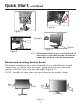
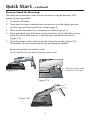
Quick Start – continued
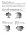
Raising and Lowering Monitor Screen
The monitor screen may be raised or lowered while in either Portrait or Land-
scape mode. To raise or lower the screen, place hands on each side of the
monitor and lift or lower to the desired height (Figure RL.1).
NOTE: Handle with care when raising or lowering the monitor screen.
Figure RL.1
Figure 7
Figure 8
Vacation
Switch
Power
Button
Figure 9
Figure 10
NOTE: The Vacation Switch is a true on/off switch. If
this switch is in the OFF position, the monitor
cannot be turned on using the front button.

6
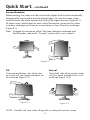
Quick Start – continued
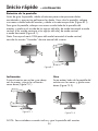
Screen Rotation
Before rotating, the screen must be raised to the highest level to avoid accidentally
damaging the screen and to avoid pinching fi ngers. To raise the screen, place
hands on each side of the monitor and lift up to the highest position (Figure RL.1).
To rotate screen, place hands on each side of the monitor screen and turn clock-
wise from Landscape to Portrait or counter-clockwise from Portrait to Landscape
(Figure R.1).
Note: To toggle the orientation of the OSM menu between Landscape and
Portrait modes, refer to the “Controls” section of this user’s manual.
Swivel
Grasp both sides of the monitor screen
with your hands and adjust the swivel
as desired (Figure TS.2).
Tilt
Grasp top and bottom sides of the moni-
tor screen with your hands and adjust the
tilt as desired (Figure TS.1).
NOTE: Handle with care when tilting and swiveling the monitor screen.
Figure R.1
Figure TS.1
Figure TS.2

7
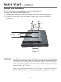
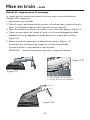
Remove Stand for Mounting
The stand can be removed in order to mount the monitor using an alternate, VESA
approved, mounting method.
1. Disconnect all cables.
2. Place hands on each side and raise the monitor up to the highest position
(see Raising and Lowering Monitor Screen page 5).
3.
Place monitor face down on a nonabrasive surface (Figure S.1).
4. Place one hand around the base and one hand on the Quick Release Lever.
Move the Quick Release Lever in the direction indicated by the arrows
(Figure S.2) .
5. Lift up the bottom of the stand to unhook it from the monitor (Figure S.3).
The monitor can now be mounted using and alternate method.
Reverse the process to reattach stand.
NOTE: Handle with care when removing monitor stand.
(Figure S.2)
Quick Start – continued
(Figure S.1)
(Figure S.3)
1. Pull lever towards stand.
2. Slide lever to the right.
1
2

8
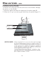
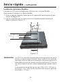
Flexible Arm Installation
This LCD monitor is designed for use with a fl exible arm.
To mount the monitor to a fl exible arm:
1. Remove the stand (see Remove Monitor Stand for Mounting page 7).
2. Use the 4 screws that are included to
attach the arm to the monitor
(Figure F.1).
Quick Start – continued
CAUTION: Use ONLY the 4 screws that are included when mounting to avoid damaging
the monitor and the stand or arm. For safety requirements, the monitor must be
mounted to an arm which guaranties the necessary stability under consideration
of the weight of the monitor. The LCD monitor should only be used with an
approved arm (e.g. GS mark).
When using mounting accessories (e.g. VESA (200 X 100)) other than VESA
(100 X 100), use the screws M4 size (Length: bracket thickness + 10mm).
(Figure F.1)
100mm
100mm
200mm

9
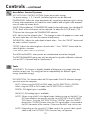
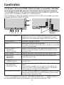
*The “LEFT/RIGHT” and “UP/DOWN” buttons functionality is interchangeable
depending on the orientation (landscape/portrait) of the OSM.
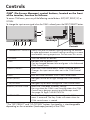
Controls
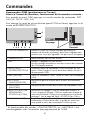
1 AMBIBRIGHT SENSOR Detects the level of ambient lighting allowing the monitor
to make adjustments to various settings resulting in a more
comfortable viewing experience. Do not cover this sensor.
2 POWER Turns the monitor on and off.
3 LED Indicates that the power is on.
Can be changed between blue and green in the Advanced
OSM Control menu.
4 INPUT/SELECT Enters the OSM Control menu. Enters OSM sub menus.
Changes the input source when not in the OSM Control
menu.
5 EXIT Exits the OSM sub menu. Exits OSM Control menu.
6 LEFT/RIGHT Navigates to the left or right through the OSM Control
menu.
7 UP/DOWN Navigates up or down through the OSM Control menu.
8 RESET/ROTATE OSM Resets the OSM back to factory settings.
Pressing when the OSM is not showing rotates the OSM
Control menu between portrait and landscape mode.*
See page 24 Tag9 OSM ROTATION.
9 KEY GUIDE The Key Guide appears on screen when the OSM control
menu is accessed. The Key Guide will rotate when the
OSM control menu is rotated.
OSM
®
(On-Screen Manager) control buttons, located on the front
of the monitor, function as follows:
To access OSM menu, press any of the following control buttons: EXIT, LEFT, RIGHT, UP, or
DOWN.
To change the input source signal when the OSM is closed, press the INPUT/SELECT button.
1 2 3 4 5 6
7
8
9
Portrait
Landscape

10
Brightness/Contrast Controls
BRIGHTNESS: Adjusts the overall image and background screen brightness.
CONTRAST: Adjusts the image brightness in relation to the background.
AUTO CONTRAST (Analog input only): Adjusts the image displayed for
non-standard video inputs.
ECO MODE: Decreases the amount of power consumed by reducing the
brightness level.
1: Decreases the brightness by 25%.
2: Decreases the brightness by 50%.
CUSTOM: Decreases the brightness level as determined by
the user. Refer to the Advanced OSM menu for custom setting instructions.
AUTO BRIGHTNESS: There are three settings for Auto Brightness.
OFF: Auto Brightness does not function.
1: Adjusts the brightness automatically by detecting the brightness level of your
environment and adjusting the monitor accordingly with the best BRIGHTNESS
setting (see page 36 for AmbiBright™ explanation), making the viewing
experience more comfortable.
2: Adjusts the BRIGHTNESS level of the monitor to the best setting based on the
amount of white being displayed on the monitor. This function does not utilize
the AmbiBright sensor.
NOTE: Do not cover the AmbiBright sensor.
When “AUTO LUMINANCE”(See page 16) is ON, this function is disabled.
BLACK LEVEL: Adjusts the black level.
Auto Adjust (Analog input only)
AUTO ADJUST:
Automatically adjusts the Image Position, H. Size, and Fine settings.
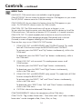
Controls – continued

11
Image Controls
LEFT / RIGHT:
Controls Horizontal Image Position within the LCD’s display area.
DOWN / UP: Controls Vertical Image Position within the
LCD’s display area
.
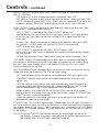
H.SIZE (V.SIZE) (Analog input only): Increases or decreases the horizontal
(or vertical) size.
If the “Auto Adjust function” does not provide a satisfactory picture,
further tuning can be performed manually using the “H. Size (or V. Size)”
function (dot clock).
To manually adjust the monitor, a Moiré test pattern should be used.
This function may alter the width of the picture. Use Left/Right Menu to center
the image on the screen.
If the H. Size (or V. Size) is set incorrectly, the screen would show vertical
banding, like the drawing on the left. The image should be clear.
FINE
(Analog input only):
If the “Auto Adjust” and the “H.Size” functions do not
provide a
satisfactory picture, further
tuning can be performed using the
“Fine” function. Adjusting
this setting improves focus, clarity and image stability.
For Fine adjustment, a
Moiré test pattern should be used. If the Fine setting is
incorrect, the screen would show horizontal banding like the drawing on the left.
The image should be clear.
AUTO FINE (Analog input only): Automatically adjusts the FINE settings.
When the AUTO FINE control is ON adjustment occurs approximately every 33
minutes.
EXPANSION: Selects the zoom mode.
FULL: The image is expanded to 1920 x 1200, regardless of the resolution.
ASPECT: The image is expanded without changing the aspect ratio.
OFF: The image is not expanded.
CUSTOM: Refer to the ADVANCED OSM Controls section of this user’s
manual for detailed instructions.
Controls – continued
Incorrect
Adjustment
Incorrect
Adjustment
Correct
Adjustment
Correct
Adjustment

12
AccuColor
®
Control Systems
ACCUCOLOR
®
CONTROL SYSTEM: Seven preset color settings.
For preset settings: 1, 2, 3 and 5, the following levels can be adjusted:
TEMPERATURE: Adjust the white temperature by increasing or decreasing this setting.
A lower color temperature will make the screen reddish and a higher color tempera-
ture will make the screen bluish.
WHITE (White Balance): If TEMPERATURE needs further adjustment, the individual R/
G/ B/ levels of the white point can be adjusted. To adjust the R/G/B levels, CUS-
TOM must be showing as the TEMPERATURE selection.
HUE: Adjusts the hue of each color
*1
. The change in color will appear on screen and
the menu color bars will show the amount of adjustment.
SATURATION: Adjusts the color depth of each color
*1
. Press the “RIGHT” button and
the color vividness increases.
OFFSET: Adjusts the color brightness of each color
*1
. Press “RIGHT” button and the
color Brightness increases.
*1: RED, YELLOW, GREEN, CYAN, BLUE, MAGENTA
The sRGB and NATIVE, color presets are standard and cannot be changed.
The PROGRAMMABLE setting can only be adjusted using color calibration software
such as NEC’s GammaComp or Spectraview II.
Tools
SHARPNESS:
This function is digitally capable of keeping a crisp image within any
resolution at any time. This setting can be set independently for different signal
timings (resolution settings).
DVI SELECTION: This function selects the DVI input mode. If the DVI selection changes,
you must restart the computer.
AUTO: When using the DVI-D to DVI-D cable, the DVI SELECTION is DIGITAL.
When using the D-SUB to DVI-A cable, the DVI SELECTION is ANALOG.
DIGITAL: DVI digital input is available.
ANALOG: DVI analog input is available.
NOTE: When using a MAC with digital output: before turning on the MAC, the
DVI Input mode on the monitor must be set to DIGITAL in the DVI SELEC
TION menu. To set the DVI SELECTION to “DIGITAL” press the SELECT
button then CONTROL button when the DVI signal cable is connected to
the DVI-I connector of the monitor. Otherwise the MAC may not turn on.
NOTE:
Depending on the type of PC/Video card or the type of video signal
cable used, the DVI SELECTION function may not operate.
Controls – continued

13
HDCP CONTENT (Digital Input Only): Selects the type of input to be used with
HDCP CONTENT.
OFF: When a PC or other computer equipment is connected, select “OFF”.
ON: When a DVD player or other type of high definition device is connected, select “ON”.
NOTE: Interlaced signals (480i, 576i, 1080i) are not supported. If you have any
problems, please refer to the Troubleshooting section of this User’s Manual.
VIDEO DETECT: Selects the method of video detection when more than one video
input source is connected to the monitor.
FIRST: If “FIRST” is selected as the VIDEO DETECT option, the
monitor displays the signal from the first input port. If there is no signal present
at the first input port, then the monitor will search for a signal from the next
input port.
If a new input signal is connected to another of the monitor’s input ports while
the monitor is in FIRST mode, the monitor DOES NOT automatically
SWITCH to the new source.
LAST: If “LAST” is selected as the VIDEO DETECT option, then
each time a new input source is detected, the monitor will automatically display
the new signal.
NONE: The monitor will only search other input ports while the power is on.
OFF TIMER:
Monitor will automatically power down after a user-determined length
of time passes. Before powering off, a message will appear on the screen asking
the user if they want to delay the turn off time by 60 minutes. Press any OSM
button to delay the turn off time.
IPM: The Intelligent Power Manager allows the monitor to enter into a power saving
mode after a period of inactivity. The IPM has three settings.
OFF: Monitor does not go into power save mode when the input signal is lost.
STANDARD: Monitor enters power save mode automatically when the input
signal is lost.
OPTION: Monitor enters power save mode automatically when the amount of
surrounding light goes below the level that is determined by the user. The level
can be determined in Tag 7 of the Advanced OSM Control menu.
When in power save mode, the LED on the front of the monitor blinks amber.
While in power save mode, push any of the front buttons, except for POWER and
SELECT to return to normal operation.
When the amount of surrounding light returns to normal levels, the monitor will
automatically return to normal mode.
COLORCOMP:
This function electronically compensates for the slight variations in
the white uniformity level, as well as for deviations in color that may occur throughout
the display area of the screen. These variations are characteristic of LCD panel
technology. This function improves the color and evens out the luminance uniformity
of the display.
NOTE: Using the COLORCOMP feature reduces the overall peak luminance of
the display. If greater luminance is desired over the uniform performance of
the display, then COLORCOMP should be turned off.
Controls – continued

14
MENU Tools
LANGUAGE: OSM control menus are available in eight languages.
OSM LEFT/RIGHT: You can choose the location where the OSM appears on your screen.
The LEFT/RIGHT submenu moves the OSM horizontally.
OSM DOWN/UP: You can choose the location where the OSM appears on your
screen. This DOWN/UP submenu moves the OSM vertically.
OSM TURN OFF: The OSM control menu will stay on as long as it is use.
You can select how long the monitor waits after the last touch of a button to shut off the
OSM control menu. Time can be set between10-120 seconds, in 5 second increments.
OSM LOCK OUT
: This control completely locks out access to some of or to all of the
OSM control functions. When attempting to activate OSM controls while in the Lock
Out mode, a screen will appear indicating the OSM controls are locked out.
There are four ways to use OSM LOCK OUT function:
1. OSM LOCK OUT with BRIGHTNESS and CONTRAST control: This mode
locks all OSM functions except for BRIGHTNESS and CONTRAST.
To activate, press the SELECT and “Up” buttons simultaneously, while in the
OSM menu.
To deactivate, press the SELECT and “Up” buttons simultaneously, while in
the OSM menu.
2. OSM LOCK OUT with no control: This mode prevents access to all
OSM functions.
To activate, press the SELECT and “Right” buttons simultaneously.
To deactivate, press the SELECT and “Right” buttons simultaneously,
while in the OSM menu.
3. OSM LOCK OUT with BRIGHTNESS (only) control: This mode locks all OSM
functions except for BRIGHTNESS.
To activate, press the SELECT, “Left” and "Down" buttons simultaneously,
while in the OSM menu.
To deactivate, press SELECT, then “Left” and "Down" buttons simultaneously
while in the OSM menu.
4. CUSTOM: refer to the Advanced OSM Menu.
OSM TRANSPARENCY: Adjusts the transparency of the OSM Menu.
OSM COLOR: “Tag window frame color”, “Item select color” and “Adjust window
frame color” can be changed to Red, Green, Blue, or Gray.
Controls – continued

15
Controls – continued
RESOLUTION NOTIFIER: The Resolution Notifier warns the user if the input signal
to the monitor is set at something other than the optimized resolution of
1920 x 1200. If the monitor detects a signal that is not at the optimized
resolution then, after 30 seconds, a warning message will appear on the screen.
When the Resolution Notifier is ON, the warning will appear every 30 seconds.
The Resolution Notifier can be turned OFF in the OSM.
HOT KEY: When this function is activated, the brightness and contrast of the
monitor can be adjusted without entering the OSM menu.
The “Left” or “Right” buttons adjust the brightness level.
The “Down” or “Up” buttons adjust the contrast level.
FACTORY PRESET: Selecting the factory preset allows the user to reset most of the
OSM control settings back to the factory settings.
Individual settings can be reset by highlighting the control that needs to be reset,
and pressing the RESET button.
Information
Provides information about the current resolution being displayed by the monitor.
Also provides technical information including which preset timing is being used as
well as the horizontal and vertical frequencies.
OSM WARNINGS: OSM Warning menus alert the user when there are
problems with the input signal. These warnings will disappear when the Exit
button is pressed.
NO SIGNAL: This warning appears when there is no Horizontal or
Vertical Sync. After power is turned on or when there is a change of input
signal, the No Signal window will appear.
RESOLUTION NOTIFIER: This warning appears when the monitor detects
a resolution other than the optimized resolution. For example, if the
optimized resolution for the monitor is 1920 x 1200 and a signal using a
resolution of 1280 x 1024 is detected, the “Resolution Notifier” warning
will appear.
OUT OF RANGE: This warns if the input signal is out of the optimized
resolution and refresh rate range that is used by monitor.
PORTRAIT WARNING: When the monitor is used in the portrait position, the
brightness value will be reduced to 300 cd/m
2
. If the Portrait Warning is ON,
a message will appear on the screen for 10 seconds.
LUMINANCE WARNING: When the backlight cannot display the desired
luminance, a message will appear on the display. To avoid this, reduce the BRIGHT-
NESS level or set the AUTO LUMINANCE function to OFF (page 16, TAG1).
Note: It is possible to change the DVI SELECTION, to change the IPM or to
change the HDCP CONTENT settings while the “NO SIGNAL” or “OUT
OF RANGE” messages are displayed.
For advanced user menu items see “Advanced OSM Controls”.

16
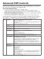
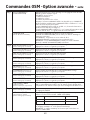
Advanced OSM Controls
In addition to the standard On Screen Menu (OSM), the Advanced OSM Control menu
allows the user to have much more control over regular OSM functions as well as ac-
cess to functions not available in the standard OSM.
To use the advanced menu
• Turn off your monitor using the front "POWER" button.
• Turn on your monitor by pushing the “POWER” and “INPUT/SELECT” button
simultaneously for at least one second. Then press one of the following front OSM
buttons: EXIT, LEFT, RIGHT, UP, or DOWN.
• You will see the Advanced OSM Control menu. This menu is larger than the standard
OSM and has numbered tags instead of icons.
• To exit the Advanced OSM, turn off and restart your monitor in the normal way.
To adjust the setting, use the buttons on the front panel to highlight the desired tag and
press "SELECT". Use the buttons to make the adjustment. Once the setting is at the
desired level press "SELECT" and then "EXIT" to go back to the previous menu.
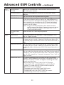
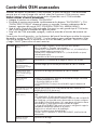
Tag 1 Brightness
Adjusts the overall image and screen background brightness.
Press “Left” or “Right” to adjust.
When AUTO LUMINANCE is OFF or 2, the brightness level is adjusted/measured using
percentage (%).
When AUTO LUMINANCE is 1 or 3, brightness level is adjusted/measured using
cd/m
2
. This is the “Estimated Brightness” level.
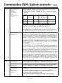
Contrast
Adjusts the image brightness and contrast in relation to the background.
Auto Contrast
(Analog input only)
Adjusts the image displayed for non-standard video inputs.
Auto Black Level
(Analog input only)
Adjusts the black level for non-standard video inputs.
ECO Mode
Decreases the amount of power consumed by reducing the
brightness level.
1: Decreases the brightness by 25%.
2: Decreases the brightness by 50%.
CUSTOM: Decreases the brightness level as determined by the user.
ECO Mode Custom
Allows the user to set a preferred brightness level when ECO Mode is in use.
Auto Brightness
AUTO BRIGHTNESS has three settings.
OFF: Auto Brightness does not function.
1: Adjusts the brightness automatically by detecting the brightness level of your environment
and adjusting the monitor accordingly with the best BRIGHTNESS setting (see page 36 for
AmbiBright™ explanation), making the viewing experience more comfortable.
2: Adjusts the BRIGHTNESS level of the monitor to the best setting based on the amount of
white being displayed on the monitor. This function does not utilize the Ambibright sensor.
NOTE: Do not cover AmbiBright sensor. When “AUTO LUMINANCE” is ON, this function
is disabled.
Black Level
Adjusts the black level.
AUTO
LUMINANCE
Stabilizes the luminosity and color of the image. While the BRIGHTNESS level is adjusting, the
numerical value blinks.
OFF: No function
1: Stabilize Luminance
2: Stabilize Color
3: Stabilize Luminance and color
Note: The AUTO LUMINANCE function is only available when “AUTO BRIGHTNESS” is OFF.
When “AUTO LUMINANCE” is 1 or 3, maximum value of the Brightness level is limited.
When “AUTO LUMINANCE” is OFF or 2, the brightness level is adjusted/ measured
using percentage(%).
When “AUTO LUMINANCE” is 1 or 3, brightness level is adjusted/measured using cd/m
2
.
This is the “Estimated Brightness” level.

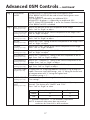
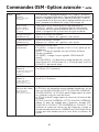
17
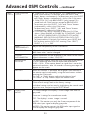
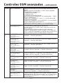
Tag 1
LOW BRIGHT
MODE
The BRIGHTNESS setting can lower the brightness level.
LOW BRIGHT MODE can be used to lower the brightness even
further, if desired.
ON: Brightness is reduced by an additional 50%.
ADVANCED: Brightness is reduced by an additional 25%.
NOTE: When PROGRAMABLE is set for the Gamma Selection (tag5),
LOW BRIGHT MODE is disabled.
Tag 2
R-H. POSITION
(Analog input only)
Adjusts the position of the RED component of the image.
Press “Left” or “Right” to adjust.
G-H. POSITION
(Analog input only)
Adjusts the position of the GREEN component of the image. Press
“Left” or “Right” to adjust.
B-H. POSITION
(Analog input only)
Adjusts the position of the BLUE component of the image.
Press “Left” or “Right” to adjust.
R-FINE
(Analog input only)
Adjusts the “FINE” setting of the RED component of the image. Press
”Left” or “Right” to adjust.
G-FINE
(Analog input only)
Adjusts the “FINE” setting of the GREEN component of the image.
Press ”Left” or “Right” to adjust.
B-FINE
(Analog input only)
Adjusts the “FINE” setting of the BLUE component of the image. Press
”Left” or “Right” to adjust.
R-SHARPNESS
(Analog input only)
Adjusts the “SHARPNESS” setting of the RED component of the im-
age. Press ”Left” or “Right” to adjust.
G-SHARPNESS
(Analog input only)
Adjusts the “SHARPNESS” setting of the GREEN component of the
image. Press ”Left” or “Right” to adjust.
B-SHARPNESS
(Analog input only)
Adjusts the “SHARPNESS” setting of the BLUE component of the im-
age. Press ”Left” or “Right” to adjust.
DVI LONG CABLE
(Digital input only)
Compensates for image degradation caused by using a long DVI
cable. There are 4 possible settings, with “0” being the lowest level
of compensation and “3” being the highest level.
The default setting is “1”.
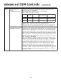
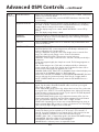
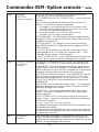
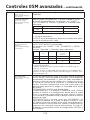
Tag 3
AUTO ADJUST
(Analog input only)
Automatically adjusts the Image Position, H. Size, and
Fine settings.
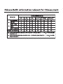
SIGNAL AD-
JUST
(Analog input only)
Determines what settings are adjusted when Auto Adjust is per-
formed. The choices are “SIMPLE” and “FULL”.
Press ”Left” or “Right” to select.
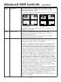
H-size, Fine, H/V Position Contrast
SIMPLE O X
FULL O O
O: Automatic Adjustment X: No Automatic Adjustment
NOTE: Automatic Adjustment does not work at
resolutions less than 800 x 600 resolution.
Advanced OSM Controls – continued
La page est en cours de chargement...
La page est en cours de chargement...
La page est en cours de chargement...
La page est en cours de chargement...
La page est en cours de chargement...
La page est en cours de chargement...
La page est en cours de chargement...
La page est en cours de chargement...
La page est en cours de chargement...
La page est en cours de chargement...
La page est en cours de chargement...
La page est en cours de chargement...
La page est en cours de chargement...
La page est en cours de chargement...
La page est en cours de chargement...
La page est en cours de chargement...
La page est en cours de chargement...
La page est en cours de chargement...
La page est en cours de chargement...
La page est en cours de chargement...
La page est en cours de chargement...
La page est en cours de chargement...
La page est en cours de chargement...
La page est en cours de chargement...
La page est en cours de chargement...
La page est en cours de chargement...
La page est en cours de chargement...
La page est en cours de chargement...
La page est en cours de chargement...
La page est en cours de chargement...
La page est en cours de chargement...
La page est en cours de chargement...
La page est en cours de chargement...
La page est en cours de chargement...
La page est en cours de chargement...
La page est en cours de chargement...
La page est en cours de chargement...
La page est en cours de chargement...
La page est en cours de chargement...
La page est en cours de chargement...
La page est en cours de chargement...
La page est en cours de chargement...
La page est en cours de chargement...
La page est en cours de chargement...
La page est en cours de chargement...
La page est en cours de chargement...
La page est en cours de chargement...
La page est en cours de chargement...
La page est en cours de chargement...
La page est en cours de chargement...
La page est en cours de chargement...
La page est en cours de chargement...
La page est en cours de chargement...
La page est en cours de chargement...
La page est en cours de chargement...
La page est en cours de chargement...
La page est en cours de chargement...
La page est en cours de chargement...
La page est en cours de chargement...
La page est en cours de chargement...
La page est en cours de chargement...
La page est en cours de chargement...
La page est en cours de chargement...
La page est en cours de chargement...
La page est en cours de chargement...
La page est en cours de chargement...
La page est en cours de chargement...
La page est en cours de chargement...
La page est en cours de chargement...
La page est en cours de chargement...
La page est en cours de chargement...
La page est en cours de chargement...
La page est en cours de chargement...
La page est en cours de chargement...
La page est en cours de chargement...
La page est en cours de chargement...
La page est en cours de chargement...
La page est en cours de chargement...
La page est en cours de chargement...
La page est en cours de chargement...
La page est en cours de chargement...
La page est en cours de chargement...
La page est en cours de chargement...
La page est en cours de chargement...
La page est en cours de chargement...
La page est en cours de chargement...
La page est en cours de chargement...
La page est en cours de chargement...
La page est en cours de chargement...
La page est en cours de chargement...
La page est en cours de chargement...
La page est en cours de chargement...
La page est en cours de chargement...
La page est en cours de chargement...
La page est en cours de chargement...
La page est en cours de chargement...
La page est en cours de chargement...
La page est en cours de chargement...
La page est en cours de chargement...
La page est en cours de chargement...
La page est en cours de chargement...
La page est en cours de chargement...
La page est en cours de chargement...
La page est en cours de chargement...
La page est en cours de chargement...
La page est en cours de chargement...
La page est en cours de chargement...
La page est en cours de chargement...
La page est en cours de chargement...
La page est en cours de chargement...
La page est en cours de chargement...
La page est en cours de chargement...
La page est en cours de chargement...
La page est en cours de chargement...
La page est en cours de chargement...
La page est en cours de chargement...
-
 1
1
-
 2
2
-
 3
3
-
 4
4
-
 5
5
-
 6
6
-
 7
7
-
 8
8
-
 9
9
-
 10
10
-
 11
11
-
 12
12
-
 13
13
-
 14
14
-
 15
15
-
 16
16
-
 17
17
-
 18
18
-
 19
19
-
 20
20
-
 21
21
-
 22
22
-
 23
23
-
 24
24
-
 25
25
-
 26
26
-
 27
27
-
 28
28
-
 29
29
-
 30
30
-
 31
31
-
 32
32
-
 33
33
-
 34
34
-
 35
35
-
 36
36
-
 37
37
-
 38
38
-
 39
39
-
 40
40
-
 41
41
-
 42
42
-
 43
43
-
 44
44
-
 45
45
-
 46
46
-
 47
47
-
 48
48
-
 49
49
-
 50
50
-
 51
51
-
 52
52
-
 53
53
-
 54
54
-
 55
55
-
 56
56
-
 57
57
-
 58
58
-
 59
59
-
 60
60
-
 61
61
-
 62
62
-
 63
63
-
 64
64
-
 65
65
-
 66
66
-
 67
67
-
 68
68
-
 69
69
-
 70
70
-
 71
71
-
 72
72
-
 73
73
-
 74
74
-
 75
75
-
 76
76
-
 77
77
-
 78
78
-
 79
79
-
 80
80
-
 81
81
-
 82
82
-
 83
83
-
 84
84
-
 85
85
-
 86
86
-
 87
87
-
 88
88
-
 89
89
-
 90
90
-
 91
91
-
 92
92
-
 93
93
-
 94
94
-
 95
95
-
 96
96
-
 97
97
-
 98
98
-
 99
99
-
 100
100
-
 101
101
-
 102
102
-
 103
103
-
 104
104
-
 105
105
-
 106
106
-
 107
107
-
 108
108
-
 109
109
-
 110
110
-
 111
111
-
 112
112
-
 113
113
-
 114
114
-
 115
115
-
 116
116
-
 117
117
-
 118
118
-
 119
119
-
 120
120
-
 121
121
-
 122
122
-
 123
123
-
 124
124
-
 125
125
-
 126
126
-
 127
127
-
 128
128
-
 129
129
-
 130
130
-
 131
131
-
 132
132
-
 133
133
-
 134
134
-
 135
135
-
 136
136


NEC LCD2690WUXI Le manuel du propriétaire
- Catégorie
- Téléviseurs
- Taper
- Le manuel du propriétaire
dans d''autres langues
- English: NEC LCD2690WUXI Owner's manual
- español: NEC LCD2690WUXI El manual del propietario
Documents connexes
-
NEC LCD19V-BK Manuel utilisateur
-
NEC Multisync LCD1990FXP-BK Manuel utilisateur
-
-
NEC MultiSync® LCD1990FXp Le manuel du propriétaire
-
NEC MULTISYNC 1940WCXM Manuel utilisateur
-
NEC MultiSync® LCD1810XBK Le manuel du propriétaire
-
-
-
NEC SpectraView® 2090 Le manuel du propriétaire
-
NEC MultiSync LCD2080UXI Manuel utilisateur