
NOTE: THIS INSTRUCTION
BOOKLET CONTAINS IMPORTANT
SAFETY INFORMATION.
PLEASE READ AND KEEP FOR
FUTURE REFERENCE.
English pg 1-15
Français pg 16-18
Español pg 19-21
Lot # 389977 04/14/16
Purchased: __________________
Be sure to give us a ring before
making any returns. 1-800-523-3987
Need help? Visit Sauder.com to view video assembly tips or chat with a live rep.
Prefer the phone? Call 1-800-523-3987.
Share your journey!
sauder.com
Night Stand
Beginnings Collection | Model 415544
Sweet stand.
Sweet dreams.

Table of Contents Assembly Tools Required
3
4
5-15
16-18
19-21
22
23
Part Identifi cation
Hardware Identifi cation
Assembly Steps
Français
Español
Safety
Warranty
Hammer
Not actual size
No. 2 Phillips Screwdriver
Tip Shown Actual Size
Skip the power trip.
This time.
415544 www.sauder.com/servicesPage 2
Scissors

Part Identifi cation
åWhile not all parts are labeled, some of the parts will have a label or an inked letter on the edge
to help distinguish similar parts from each other. Use this part identifi cation to help identify similar parts.
FF RIGHT END (1)
GG LEFT END (1)
HH TOP (1)
II BOTTOM (1)
JJ SKIRT (1)
KK BACK (1)
NN DRAWER FRONT (1)
D217 DRAWER SIDE (2)
D218 DRAWER BACK (1)
D613 DRAWER BOTTOM (1)
Now you know
our ABCs.
415544www.sauder.com/services Page 3
FF
GG
HH
II
JJ
KK
NN
D217
D217
D218
D613

Hardware Identifi cation
åScrews are shown actual size. You may receive extra hardware with your unit.
415544 www.sauder.com/servicesPage 4
SLIDE SET - 1
16B HIDDEN CAM - 4
1F CAM DOWEL - 4
2F
ANGLE BRACKET - 3
5G DRAWER FRONT
BRACKET - 2
30G
PULL - 1
45K NAIL - 8
1N APPLIQUE CARD - 1
29P
BLACK 9/16" LARGE HEAD SCREW - 8
1S BLACK 1-7/8" FLAT HEAD SCREW - 4
2S
BLACK 1/2" FLAT HEAD SCREW - 4
43S BLACK 1-1/2" PAN HEAD SCREW - 4
49S
52S SILVER 3/4" PAN HEAD SCREW - 4 SILVER 3/4" MACHINE SCREW - 2
53S

Step 1 Look for this icon. It means a
video assembly tip is available at
www.sauder.com/services/tips
å Assemble your unit on a carpeted fl oor or on the empty
carton to avoid scratching your unit or the fl oor.
å Push four HIDDEN CAMS (1F) into the ENDS (FF and GG).
Then, insert the metal end of a CAM DOWEL (2F) into
each HIDDEN CAM.
415544www.sauder.com/services Page 5
GG
FF
Do not tighten the HIDDEN CAMS in this step.
Insert the metal end of the CAM
DOWEL into the HIDDEN CAM.
Arrow
Arrow
1F
2F
(4 used)

Step 2
å NOTE: Before beginning this step, separate the SLIDES from the SLIDE SETS (16B) and the DRAWER PINS at the end of
the SLIDES using a SCISSORS. Save the DRAWER PINS. You will use them in Step 10.
å Fasten the SLIDES (16B) to the ENDS (FF and GG). Use four SILVER 3/4" PAN HEAD SCREWS (52S) through the fi rst and
last holes in the SLIDES.
å NOTE: The SLIDES are marked "RIGHT" and "LEFT" for easy identifi cation. The SLIDE marked "RIGHT" will fasten to the
RIGHT END (FF) and the SLIDE marked "LEFT" will fasten to the LEFT END (GG). There are also arrows on the SLIDES for
correct positioning on the ENDS.
415544 www.sauder.com/servicesPage 6
FF
GG
Finished edge
Angled edge
Straight edge
Notch
RIGHT SLIDE
DRAWER PIN
(Save for Step 10)
Using your Scissors, separate the
SLIDES and the DRAWER PINS
16B
16B
16B
SILVER 3/4" PAN HEAD SCREW
(4 used in this step)
52S
Finished edge
LEFT SLIDE
Surface with
HIDDEN CAMS
Surface with
HIDDEN CAMS

å Fasten three ANGLE BRACKETS (5G) to the BOTTOM (II) and
SKIRT (JJ). Use three BLACK 9/16" LARGE HEAD SCREWS (1S).
å NOTE: Be sure the edges of the ANGLE BRACKETS are even
with the edges of the BOTTOM (II) and SKIRT (JJ).
Step 3
415544www.sauder.com/services Page 7
5G
5G
II
JJ
Surface with holes
BLACK 9/16" LARGE HEAD SCREW
(3 used in this step)
1S
Some assembly
(and snacks) required.

Step 4
å Fasten the TOP (HH) to the ENDS (FF and GG). Tighten
four HIDDEN CAMS.
415544 www.sauder.com/servicesPage 8
FF
GG
HH
Start Tighten
Arrow
Minimum
190 degrees
Caution
Risk of damage or
injury. HIDDEN CAMS
must be completely
tightened. HIDDEN
CAMS that are not
completely tightened
may loosen, and parts
may separate. To
completely tighten:
Arrow
Maximum
210 degrees
Finished edge
Surface with
HIDDEN CAMS
Surface without
HIDDEN CAMS
Surface
with holes
Finished edge

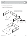
å Fasten the BOTTOM (II) to the ENDS (FF and GG). Use four
BLACK 1-7/8"FLAT HEAD SCREWS (2S).
å Fasten the SKIRT (JJ) to the BOTTOM (II) and ENDS (FF and GG).
Use three BLACK 9/16" LARGE HEAD SCREWS (1S).
Step 5
415544www.sauder.com/services Page 9
FF
GG II
JJ
Do not stand the unit upright without the
BACK fastened. The unit may collapse.
Caution
BLACK 9/16" LARGE HEAD SCREW
(3 used for the ANGLE BRACKETS)
1S
ANGLE BRACKET
should be here.
BLACK 1-7/8" FLAT HEAD SCREW
(4 used in this step)
2S

Step 6
å Carefully turn the Night Stand over onto its front edges. Lay
the BACK (KK) over the unit.
å Make equal margins along all three edges of the BACK (KK).
Push on opposite corners of your unit if needed to make
it "square".
å Fasten the BACK (KK) to the unit using the NAILS (1N).
415544 www.sauder.com/servicesPage 10
FF
GG
HH
KK
Edge without holes
Do not stand the unit upright without the
BACK fastened. The unit may collapse.
Caution
NAIL
(8 used in this step)
1N

å Fasten the DRAWER SIDES (D217) to the DRAWER BACK (D218).
Use four BLACK 1-1/2" PAN HEAD SCREWS (49S).
å Slide the DRAWER BOTTOM (D613) into the grooves in the
DRAWER SIDES (D217) and DRAWER BACK (D218).
Step 7
415544www.sauder.com/services Page 11
Be sure the grooves in each part line up
with each other on the inside of the drawer.
D217
D217
D218
D217
D217
D218
D613
Groove
BLACK 1-1/2" PAN HEAD SCREW
(4 used in this step)
49S
Finished surface

Step 8
å Fasten two DRAWER FRONT BRACKETS (30G) to the
DRAWER SIDES (D217). Use four BLACK 1/2" FLAT
HEAD SCREWS (43S).
415544 www.sauder.com/servicesPage 12
D217
D217
30G
30G
BLACK 1/2" FLAT HEAD SCREW
(4 used in this step)
43S
Don't worry. It isn't
Rome. This can be built
in a day.

å Fasten the DRAWER FRONT (NN) to the DRAWER SIDES (D217).
Use two BLACK 9/16" LARGE HEAD SCREWS (1S).
å Fasten the PULL (45K) to the DRAWER FRONT (NN). Use two
SILVER 3/4" MACHINE SCREWS (53S).
Step 9
415544www.sauder.com/services Page 13
D217
D217
NN
45K
SILVER 3/4" MACHINE SCREW
(2 used for the PULL)
53S
D613
BLACK 9/16" LARGE HEAD SCREW
(2 used for the BRACKETS)
1S
Be sure the DRAWER
BOTTOM (D613) inserts
into the groove in the
DRAWER FRONT (NN).

Step 10
å Carefully stand the unit upright.
å To insert the drawer into the unit, line up the grooves on the DRAWER
SIDES (D217) with the SLIDES in the unit. Slide the drawer into the unit
until it is about 3" or 4" away from the back of the unit.
å Using your hammer, gently tap two DRAWER PINS (from Step 2) into
the holes in the DRAWER SIDES (D217).
å NOTE: The DRAWER PINS are used as a locking system for the
drawer. When the DRAWER PINS are in place, you will not be able to
remove the drawer from the unit.
415544 www.sauder.com/servicesPage 14
D217
D217
DRAWER PIN

å Peel the APPLIQUES from the APPLIQUE CARD (29P). Stick the APPLIQUES over the heads
of each SCREW in the ENDS (FF and GG).
å NOTE: Please read the back pages of the instruction booklet for important safety information.
å This completes assembly. Clean with your favorite furniture polish or a damp cloth. Wipe dry.
Step 11
415544www.sauder.com/services Page 15
29P
FF
GG
25 lbs.
25 lbs.
15 lbs.
And to celebrate, why not share your success story?

A l’usage exclusif du
Canada Noter la date
d’achat de cet élément
et conserver le livret
pour future référence.
Pour contacter Sauder
en ce qui concerne cet
élément, faire référence
au numéro de lot et
numéro de modèle en
appelant notre numéro
sans frais.
Lot nº : ____________
Date de
l’achat: ____________
LISTE DE PIÈCES
REFERENCE DESCRIPTION QUANTITÉ
LISTE DE PIÈCES
REFERENCE DESCRIPTION QUANTITÉ
NOUS SOMMES LA POUR VOUS AIDER!
Nous faisons de notre mieux pour nous assurer que votre meuble
arrive dans d’excellentes conditions. Nos représentants du service
Clientèle sont aimables et prêts à vous aider au cas où une pièce
aurait été endommagée ou manquerait (ou si vous aviez besoin
d’aide pour l’assemblage). NE RAMENEZ PAS LE MEUBLE AU
MAGASIN. Au Canada, composez ce numéro d’appel gratuit:
1-800-523-3987
Du lundi au vendredi, de 9 heures du matin à
5:30 heures du soir (horaire Côte Est)
(sauf jours fériés)
Si une pièce a besoin d’être remplacée, la pièce de remplacement
sera envoyée dans les 48 heures. (Sauf week-ends et jours fériés)
Utilisez les instructions d’assemblage en français avec les
schémas étape par étape du manuel d’instruction en anglais.
Chaque étape en français correspond à la même étape
en anglais. La pièce devant être attachée à l’élément est
représentée en gris sur les schémas de chaque étape pour plus
de précision. Comparer la “Liste de pièces” ci-dessous avec
la “PART IDENTIFICATION” du manuel en anglais pour vous
familiariser avec les pièces avant l’assemblage.
REMARQUE : CE MANUEL D’INSTRUCTIONS CONTIENT
D’IMPORTANTES INFORMATIONS RELATIVES À LA SÉCURITÉ.
À LIRE ET CONSERVER POUR TOUTE RÉFÉRENCE FUTURE.
ChevetModèle 415544
16B ENSEMBLE DE COULISSE ...................................1
1F EXCENTRIQUE ESCAMOTABLE .....................4
2F CHEVILLE D'EXCENTRIQUE ..............................4
5G CONSOLE À ÉQUERRE .........................................3
30G CONSOLE DE DEVANT DE TIROIR ..............2
45K POIGNÉE .............................................................................1
1N CLOU ....................................................................................8
29P FICHE D'APPLIQUÉS ................................................1
1S VIS TÊTE LARGE 14 mm NOIRE .....................8
2S VIS TÊTE PLATE 48 mm NOIRE .....................4
43S VIS TÊTE PLATE 13 mm NOIRE ......................4
49S VIS TÊTE GOUTTE DE SUIF
38 mm NOIRE ...............................................................4
52S VIS TÊTE GOUTTE DE SUIF
19 mm ARGENT ...........................................................4
53S VIS À MÉTAUX 19 mm ARGENT.....................2
FF EXTRÉMITÉ DROITE ..................................................1
GG EXTRÉMITÉ GAUCHE ...............................................1
HH DESSUS ...............................................................................1
II DESSOUS ...........................................................................1
JJ PLINTHE ..............................................................................1
KK ARRIÈRE ..............................................................................1
NN DEVANT DE TIROIR ....................................................1
D217 CÔTÉ DE TIROIR .........................................................2
D218 ARRIÈRE DE TIROIR ...................................................1
D613 FOND DE TIROIR ..........................................................1
415544 www.sauder.com/servicesPage 16

ÉTAPE 1
Assembler l'élément sur un sol à moquette ou sur le carton vide
pour éviter d'endommager l'élément ou le sol.
Enfoncer quatre EXCENTRIQUES ESCAMOTABLES (1F) dans
les EXTRÉMITÉS (FF et GG). Ensuite, insérer l'extrémité en
métal de la CHEVILLE D'EXCENTRIQUE (2F) dans chaque
EXCENTRIQUE ESCAMOTABLE.
ÉTAPE 2
REMARQUE : Avant de commencer cette étape, séparer les
COULISSES des JEUX DE COULISSES (16B) et les GOUPILLES
DE TIROIR à l’extrémité des COULISSES à l’aide d’une paire de
CISEAUX. Conserver les GOUPILLES DE TIROIR. On les utilisera
à l’Étape 10.
Fixer les COULISSES (16B) aux EXTRÉMITÉS (FF et GG). Utiliser
quatre VIS TÊTE GOUTTE DE SUIF 19 mm ARGENTÉES (52S) à
travers les premiers et derniers trous des COULISSES.
REMARQUE : Les COULISSES ont une inscription « RIGHT »
(droite) et « LEFT » (gauche) pour faciliter leur identifi cation.
Les COULISSES marquées « RIGHT » [droite] se fi xeront sur
l’EXTRÉMITÉ DROITE (FF) et les COULISSES marquées «
LEFT » [gauche] se fi xeront sur l’EXTRÉMITÉ GAUCHE (GG).
Il ya également des fl èches sur les COULISSES pour leur
positionnement correct sur les EXTRÉMITÉS.
ÉTAPE 4
Fixer le DESSUS (HH) aux EXTRÉMITÉS (FF et GG). Serrer quatre
EXCENTRIQUES ESCAMOTABLES.
Attention: Risque des dégâts ou blessures. Les Excentriques
Escamotables doivent être serrés à bloc. Les Excentriques
Escamotables que ne sont pas serrées à bloc peuvent desserrer
et les pièces peuvent séparer. Pour serrer à bloc, faire tourner
l'excentrique escamotable de 210 degrés.
ÉTAPE 5
Fixer le DESSOUS (II) aux EXTRÉMITÉS (FF et GG). Utiliser quatre
VIS TÊTE PLATE 48 mm NOIRES (2S).
Fixer la PLINTHE (JJ) au DESSOUS (II) et aux EXTRÉMITÉS (FF
et GG). Utiliser trois VIS TÊTE LARGE 14 mm NOIRES (1S).
ÉTAPE 3
Fixer trois CONSOLES À ÉQUERRE (5G) au DESSOUS (II) et à la
PLINTHE (JJ). Utiliser trois VIS TÊTE LARGE 14 mm NOIRES (1S).
REMARQUE : S'assurer que les chants des CONSOLES À ÉQUERRE
sont à fl eur des chants du DESSOUS (II) et de la PLINTHE (JJ).
ÉTAPE 6
Attention: Ne pas relever l'élément dans sa position verticale
avant d'avoir fi xé l’ARRIÈRE. L'élément risque de s'e ondrer.
Avec précaution, retourner le Chevet sur ses chants avant. Placer
l'ARRIÈRE (KK) sur l'élément.
Veiller à avoir des marges égales le long trois chants de
l'ARRIÈRE (KK). Si besoin est, enfoncer sur les coins opposés de
l'élément pour s'assurer d'être « d'équerre ».
Fixer l'ARRIÈRE (KK) à l'élément à l'aide des CLOUS (1N).
415544www.sauder.com/services Page 17

ÉTAPE 7
Fixer les CÔTÉS DE TIROIR (D217) à l’ARRIÈRE DE TIROIR (D218).
Utiliser quatre VIS TÊTE GOUTTE DE SUIF 38 mm NOIRES (49S).
Enfi ler le FOND DE TIROIR (D613) dans les rainures des CÔTÉS
DE TIROIR (D217) et de l'ARRIÈRE DE TIROIR (D218).
ÉTAPE 8
Fixer les CONSOLES DE DEVANT DE TIROIR (30G) aux
CÔTÉS DE TIROIR (D217). Utiliser quatre VIS TÊTE
PLATE 13 mm NOIRES (43S).
ÉTAPE 10
Avec précaution, placer l'élément dans sa position verticale.
Pour insérer le tiroir dans l'unité, aligner les rainures des CÔTÉS
DE TIROIR (D217) avec les COULISSES de l'unité. Faire glisser le
tiroir dans l’unité jusqu’à ce qu’il se trouve à environ 7,6 cm ou 10
cm de l’arrière de l’unité.
À l’aide d’un marteau, enfoncer délicatement deux GOUPILLES DE
TIROIR (de l’Étape 2) dans les trous des CÔTÉS DE TIROIR (D217).
REMARQUE : Les GOUPILLES DE TIROIR sont utilisées comme
système de verrouillage pour le tiroir. Lorsque les GOUPILLES DE
TIROIR sont en place, il n’est pas possible de retirer le tiroir
de l’unité.
ÉTAPE 11
Décoller les APPLIQUÉS de la FICHE D'APPLIQUÉS (29P).
Centrer les APPLIQUÉS sur la tête de la chaque VIS visible dans
les EXTRÉMITÉS (FF et GG).
REMARQUE : Prière de lire les informations importantes sur la
sécurité fi gurant sur les pages arrière du manuel d’instructions.
Ceci complète l'assemblage. Nettoyer à l’aide d’une encaustique
pour meubles ou d’un chi on humide. Essuyer.
ÉTAPE 9
Fixer le DEVANT DE TIROIR (NN) aux CÔTÉS DE TIROIR (D217).
Utiliser deux VIS TÊTE LARGE 14 mm NOIRES (1S).
Fixer la POIGNÉE (45K) au DEVANT DE TIROIR (NN). Utiliser deux
VIS À MÉTAUX 19 mm ARGENTÉES (53S).
415544 www.sauder.com/servicesPage 18

A l’usage exclusif du
Canada Noter la date
d’achat de cet élément
et conserver le livret
pour future référence.
Pour contacter Sauder
en ce qui concerne cet
élément, faire référence
au numéro de lot et
numéro de modèle en
appelant notre numéro
sans frais.
Lot nº : ____________
Date de
l’achat: ____________
16B JUEGO DE CORREDERA .......................................1
1F EXCÉNTRICO ESCONDIDO ...............................4
2F PASADOR DE EXCÉNTRICO ..............................4
5G SOPORTE ANGULAR ..............................................3
30G MÉNSULA DE CARA DE CAJÓN ....................2
45K TIRADOR .............................................................................1
1N CLAVO .................................................................................8
29P TARJETA CON APLICACIONES .......................1
1S TORNILLO NEGRO DE CABEZA
GRANDE de 14 mm ...................................................8
2S TORNILLO NEGRO DE CABEZA
PERDIDA de 48 mm .................................................4
43S TORNILLO NEGRO DE CABEZA
PERDIDA de 13 mm ..................................................4
49S TORNILLO NEGRO DE CABEZA
REDONDA de 38 mm ..............................................4
52S TORNILLO PLATEADO DE
CABEZA REDONDA de 19 mm ........................4
53S TORNILLO PLATEADO PARA
METAL de 19 mm........................................................2
FF EXTREMO DERECHO ...............................................1
GG EXTREMO IZQUIERDO ............................................1
HH PANEL SUPERIOR .......................................................1
II FONDO .................................................................................1
JJ FALDÓN ...............................................................................1
KK DORSO .................................................................................1
NN CARA DE CAJÓN .........................................................1
D217 LADO DE CAJÓN ........................................................2
D218 DORSO DE CAJÓN ....................................................1
D613 FONDO DE CAJÓN ....................................................1
LISTA DE PARTES
ITEM DESCRIPCIÓN CANTIDAD
ESTAMOS AQUI PARA AYUDAR!
Tratamos de asegurar que su mueble llega en condición excelente.
Nuestros representantes de Servicio al Cliente son amables y
listos para ayudarle con servicio rápido y efi ciente si una parte
está defectuosa o ausente (o si necesita ayuda con el ensamblaje).
NO DEVUELVA LA UNIDAD A LA TIENDA. Llame este número sin
cargo:
1-800-523-3987
Lunes a viernes, 9:00 a.m. - 5:30 p.m.
Hora ofi cial del Este
(excepto días festivos)
Si requiere un repuesto de una parte, será enviado dentro de
48 horas (excepto los fi nes de semana y días festivos)
Use estas instrucciones de ensamblaje en español junto con las
fi guras paso-a-paso provistas en el folleto inglés. Cada paso
en español corresponde al mismo paso en inglés. Se destacan
las fi guras de cada paso con una tonalidad oscura para mostrar
precisamente cual parte se debe montar a la unidad. Compare
la “Lista de Part” abajo con la “Part Identifi cation” en el folleto en
inglés para familiarizarse con Las partes de ensamblaje.
NOTA: ESTE FOLLETO DE INSTRUCCIONES CONTIENE
INFORMACIÓN IMPORTANTE SOBRE LA SEGURIDAD. POR
FAVOR LEA Y GUÁRDELO PARA REFERENCIA EN EL FUTURO.
LISTA DE PARTES
ITEM DESCRIPCIÓN CANTIDAD
Mesa de nocheModelo 415544
415544www.sauder.com/services Page 19

PASO 1
Ensamble la unidad sobre un piso alfombrado o sobre el cartón
vacío para evitar rayar la unidad o el piso.
Empuje cuatro EXCÉNTRICOS ESCONDIDOS (1F) dentro de
los EXTREMOS (FF y GG). A continuación, inserte el extremo de
metal de un PASADOR DE EXCÉNTRICO (2F) dentro de cada
EXCÉNTRICO ESCONDIDO.
PASO 2
NOTA: Antes de comenzar con este paso, separe las CORREDERAS
del juego de CORREDERAS (16B) y los PASADORES DEL CAJÓN
en los extremos de las CORREDERAS utilizando unas tijeras.
Guarde los PASADORES DEL CAJÓN Se van a utilizar más
adelante en el paso 10.
Fije las CORREDERAS (16B) a los EXTREMOS (FF y GG). Use cuatro
TORNILLOS PLATEADOS DE CABEZA REDONDA de 19 mm (52S)
a través de primero y el último agujero en las CORREDERAS.
NOTA: Las CORREDERAS tienen una inscripción "RIGHT" (derecha)
y una inscripción "LEFT" (izquierda) para identifi carlas fácilmente.
Las CORREDERAS marcadas "RIGHT" (derecha) se fi jan en el
EXTREMO DERECHO (FF) y las CORREDERAS marcadas "LEFT"
(izquierda) se fi jan en el EXTREMO IZQUIERDO (GG). También hay
fl echas en las CORREDERAS para el posicionamiento correcto en
los EXTREMOS.
PASO 4
Fije el PANEL SUPERIOR (HH) a los EXTREMOS (FF y GG).
Apriete cuatro EXCÉNTRICOS ESCONDIDOS.
Precaución: Riesgo de daños o heridas. Los Excéntricos
Escondidos deben apretarse completamente. Los Excéntricos
Escondidos que no se aprieten completamente se afl ojarán y las
partes pueden separarse. Para apretar completamente, atornille el
excéntrico escondido 210 grados.
PASO 5
Fije el FONDO (II) a los EXTREMOS (FF y GG). Utilice cuatro
TORNILLOS NEGROS DE CABEZA PERDIDA de 48 mm (2S).
Fije el FALDÓN (JJ) al FONDO (II) y a los EXTREMOS (FF y GG). Utilice
tres TORNILLOS NEGROS DE CABEZA GRANDE de 14 mm (1S).
PASO 3
Fije tres SOPORTES ANGULARES (5G) al FONDO (II) y al
FALDÓN (JJ). Utilice tres TORNILLOS NEGROS DE CABEZA
GRANDE de 14 mm (1S).
NOTA: Asegúrese que los bordes de los SOPORTES ANGULARES
estén nivelados con los bordes del FONDO (II) y FALDÓN (JJ).
PASO 6
Precaución: No coloque la unidad en posición vertical hasta que se
fi je el DORSO. La unidad podría caerse.
Cuidadosamente voltee la Mesa de Noche para que repose sobre
los bordes delanteros. Coloque el DORSO (KK) sobre la unidad.
Los márgenes a lo largo de los tres bordes del DORSO (KK)
deben estar uniformes. Empuje sobre las esquinas opuestas de la
unidad si es requerido para hacerla "cuadrada."
Fije el DORSO (KK) a la unidad utilizando los CLAVOS (1N).
415544 www.sauder.com/servicesPage 20
La page est en cours de chargement...
La page est en cours de chargement...
La page est en cours de chargement...
La page est en cours de chargement...
-
 1
1
-
 2
2
-
 3
3
-
 4
4
-
 5
5
-
 6
6
-
 7
7
-
 8
8
-
 9
9
-
 10
10
-
 11
11
-
 12
12
-
 13
13
-
 14
14
-
 15
15
-
 16
16
-
 17
17
-
 18
18
-
 19
19
-
 20
20
-
 21
21
-
 22
22
-
 23
23
-
 24
24


dans d''autres langues
- English: Sauder 415544 Operating instructions
- español: Sauder 415544 Instrucciones de operación
Documents connexes
-
Sauder 413081 Manuel utilisateur
-
-
-
-
-
-
-
-
-