WAGNER Control Pro 130 Power Tank Le manuel du propriétaire
- Catégorie
- Pulvérisateur de peinture
- Taper
- Le manuel du propriétaire

0918 • Form No. 0580686B
CONTROL PRO
™
130 POWER TANK
OWNER‘S MANUAL • GUIDE D‘UTILISATION •
MANUAL DEL PROPIETARIO
READ THIS MANUAL FOR COMPLETE INSTRUCTIONS •
LIRE CE MANUEL POUR OBTENIR DES DIRECTIVES COMPLÈTES •
LEA ESTE MANUAL PARA OBTENER LAS INSTRUCCIONES COMPLETAS
wagner-group.com
EN
ES
F
ENGLISH P. 2
FRANÇAIS P. 20
ESPAÑOL P. 38

2
EN
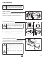
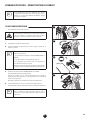
IMPORTANT SAFETY INFORMATION
TABLE OF CONTENTS
IMPORTANT SAFETY INFORMATION ___________________ 24
Explanation of Symbols ________________________________ 2
Grounding Instructions ________________________________ 3
Important Electrical Information _________________________ 3
Safety Hazards _____________________________________ 3-4
GENERAL INFORMATION _______________________________ 5
Specications ________________________________________ 5
PARTS AND COMPONENTS _____________________________ 6
Assembly ___________________________________________ 6
BEFORE YOU BEGIN ____________________________________ 7
Locking the Spray Gun _________________________________ 7
Pressure Relief Procedure ______________________________ 7
Moving / Emptying the Sprayer __________________________ 7
LOAD MATERIAL ______________________________________ 8
SPRAYING ____________________________________________ 9
PRACTICE SPRAYING _________________________________ 10
SPRAYING TROUBLESHOOTING _____________________ 1112
Clear the Spray Tip ___________________________________ 11
Clean the Inlet Filter __________________________________ 12
SHORT TERM STORAGE _______________________________ 13
CLEANUP _________________________________________ 1415
LONG TERM STORAGE ________________________________ 16
MAINTENANCE ____________________________________ 1718
Cleaning the Inlet Valve _______________________________ 17
Cleaning the Outlet Valve _____________________________ 18
TROUBLESHOOTING __________________________________ 19
PARTS LIST _______________________________________ 5658
WARRANTY __________________________________________ 59
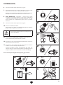
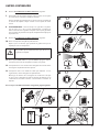
EXPLANATION OF SYMBOLS
Read all safety information before operating the equipment. Save
these instructions.
To reduce the risks of re or explosion, electrical shock and the
injury to persons, read and understand all instructions included in
this manual. Be familiar with the controls and proper usage of the
equipment.
This symbol indicates a potential hazard
that may cause serious injury or loss of life.
Important safety information will follow.
At
tention
This symbol indicates a potential hazard to you
or to the equipment. Important information
that tells how to prevent damage to the
equipment or how to avoid causes of minor
injuries will follow.
Danger of skin injection
Danger of re from solvent and paint fumes
Danger of explosion from solvent, paint fumes
and incompatible materials
Danger of injury from inhalation of harmful
vapors
Electric shock hazard
i
Notes give important information which
should be given special attention.
The Control Pro can only be used with spray
tips, hoses or spray guns that are Control Pro
compatible. Do not use any non-Control Pro
accessories with this system.

EN
3
IMPORTANT SAFETY INFORMATION
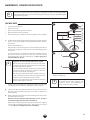
GROUNDING INSTRUCTIONS
This product must be grounded. In the event of an electrical short
circuit, grounding reduces the risk of electric shock by providing an
escape wire for the electric current. This product is equipped with a
cord having a grounding wire with an appropriate grounding plug.
The plug must be plugged into an outlet that is properly installed
and grounded in accordance with all local codes and ordinances.
WARNING - Improper installation of the grounding
plug can result in a risk of electric shock.
If repair or replacement of the cord or plug is necessary, do not
connect the green grounding wire to either at blade terminal. The
wire with insulation having a green outer surface with or without
yellow stripes is the grounding wire and must be connected to the
grounding pin.
Check with a qualied electrician or serviceman if the grounding
instructions are not completely understood, or if you are in doubt
as to whether the product is properly grounded. Do not modify the
plug provided. If the plug will not t the outlet, have the proper
outlet installed by a qualied electrician.
This product is for use on a nominal 120 volt circuit and has a
grounding plug that looks like the plug illustrated below. Make
sure that the product is connected to an outlet having the same
conguration as the plug. No adapter should be used with this
product.
Grounded Outlet
Grounding Pin
Cover for grounded outlet box
At
tention
When the sprayer is used with a generator or
uncontrolled line voltage, the use of Wagner’s “Line
Surge Protector” (P/N 800-935) is recommended.
i
Make sure to check for grounding continuity after
service is performed on any electrical components.
Use an ohmmeter to determine that there is
continuity between accessible dead-metal parts
of the product and the grounding blade of the
attachment plug.
IMPORTANT ELECTRICAL INFORMATION
At
tention
Use only a 3-wire extension cord that has a 3-blade
grounding plug and a 3-slot receptacle that will
accept the plug on the product.
Make sure your extension cord is in good condition. When using an
extension cord, be sure to use one heavy enough to carry the current
your product will draw. An undersized cord will cause a drop in line
voltage resulting in loss of power and overheating.
A 14 or 12 gauge cord is recommended (see chart). If an extension
cord is to be used outdoors, it must be marked with “SJW” or “SJTW”.
For example, a designation of SJTW would indicate that the cord
would be appropriate for outdoor use.
Cord gauge Maximum cord length
12 150 feet
14 100 feet
Wagner accessory extension cords recommended:
P/N 0090241 20 foot extension cord
P/N 0090242 35 foot extension cord
SAFETY HAZARDS
WARNING: INJECTION INJURY
A high pressure paint stream produced by this
equipment can pierce the skin and underlying
tissues, leading to serious injury and possible
amputation. See a physician immediately.
PREVENTION:
• Do not aim the gun at, or spray any person or animal.
• Keep hands and other body parts away from the discharge. For
example, do not try to stop leaks with any part of the body.
• NEVER put your hand in front of the gun. Gloves will not provide
protection against an injection injury.
• ALWAYS keep the tip guard in place while spraying. The tip
guard provides some protection but is mainly a warning device.
• Only use a nozzle tip specied by the manufacturer.
• Use caution when cleaning and changing nozzle tips. In the case
where the nozzle tip clogs while spraying, ALWAYS lock gun
trigger, shut pump o, and release all pressure before servicing,
cleaning tip or guard, or changing tip. Pressure will not be
released by turning o the motor. The PRIME/SPRAY valve
or pressure bleed valve must be turned to their appropriate
positions to relieve system pressure. Refer to PRESSURE RELIEF
PROCEDURE described in the pump manual (page 7).
• Do not leave the unit energized or under pressure while
unattended. When the unit is not in use, turn o the unit and
relieve the pressure in accordance with the manufacturer’s
instructions.

4
EN
IMPORTANT SAFETY INFORMATION
• High-pressure spray is able to inject toxins into the body and
cause serious bodily injury. In the event that injection occurs,
seek medical attention immediately.
• Check hoses and parts for signs of damage, a leak can inject
material into the skin. Inspect hose before each use. Replace
any damaged hoses or parts. Only use Wagner original-high-
pressure hoses in order to ensure functionality, safety and
durability.
• This system is capable of producing 1600 PSI / 11.1 MPa. Only
use replacement parts or accessories that are specied by the
manufacturer and that are rated a minimum of 1600 PSI. This
includes spray tips, nozzle guards, guns, extensions, ttings, and
hose.
• Always engage the trigger lock when not spraying. Verify the
trigger lock is functioning properly.
• Verify that all connections are secure before operating the unit.
• Know how to stop the unit and bleed pressure quickly. Be
thoroughly familiar with the controls. Pressure will not be released
by turning o the motor. The PRIME/SPRAY valve or pressure
bleed valve must be turned to their appropriate positions to
relieve system pressure. Refer to PRESSURE RELIEF PROCEDURE
described in the pump manual (page 7).
• Always remove the spray tip before ushing or cleaning the
system.
i
NOTE TO PHYSICIAN: Injection into the skin is
a traumatic injury which can lead to possible
amputation. It is important to treat the injury
as soon as possible. DO NOT delay treatment
to research toxicity. Toxicity is a concern with
some coatings injected directly into the blood
stream. Consultation with a plastic surgeon or
reconstructive hand surgeon may be advisable.
WARNING: EXPLOSION OR FIRE
Solvent and paint fumes can explode or ignite.
Severe injury and/or property damage can occur.
PREVENTION:
• Do not spray ammable or combustible materials near an
open ame, pilot lights or sources of ignition such as hot
objects, cigarettes, motors, electrical equipment and electrical
appliances. Avoid creating sparks from connecting and
disconnecting power cords.
• Do not spray or clean with liquids having a ash point of less
than 38ºC (100ºF). Flash point is the temperature at which a uid
can produce enough vapor to ignite.
• Paint or solvent owing through the equipment is able to result
in static electricity. Static electricity creates a risk of re or
explosion in the presence of paint or solvent fumes. All parts
of the spray system, including the pump, hose assembly, spray
gun and objects in and around the spray area shall be properly
grounded to protect against static discharge and sparks. Use
only conductive or grounded high-pressure airless paint sprayer
hoses specied by the manufacturer.
• Verify that all containers and collection systems are grounded to
prevent static discharge.
• Connect to a grounded outlet and use grounded extension
cords (electric models only). Do not use a 3 to 2 adapter.
• Do not use a paint or solvent containing halogenated
hydrocarbons. Such as chlorine, bleach mildewcide, methylene
chloride and trichloroethane. They are not compatible with
aluminum. Contact the coating supplier about compatibility of
material with aluminum.
• Keep spray area well ventilated. Keep a good supply of fresh
air moving through the area to keep the air within the spray
area free from accumulation of ammable vapors. Keep pump
assembly in well ventilated area. Do not spray pump assembly.
• Do not smoke in the spray area.
• Do not operate light switches, engines, or similar spark
producing products in the spray area.
• Keep area clean and free of paint or solvent containers, rags, and
other ammable materials.
• Know the contents of the paint and solvents being sprayed.
Read all material Safety Data Sheets (SDS) and container labels
provided with the paints and solvents. Follow the paint and
solvent manufacture’s safety instructions.
• Place pump at least 20 feet (6 meters) from the spray object in
a well ventilated area (add more hose if necessary). Flammable
vapors are often heavier than air. Floor area must be extremely
well ventilated. The pump contains arcing parts that emit sparks
and can ignite vapors.
• Plastic can cause static sparks. Never hang plastic to enclose
spray area. Do not use plastic drop cloths when spraying
ammable material.
• Fire extinguisher equipment shall be present and working.

EN
5
IMPORTANT SAFETY INFORMATION GENERAL INFORMATION
WARNING: HAZARDOUS VAPORS
Paints, solvents, insecticides, and other materials
can be harmful if inhaled or come in contact
with the body. Vapors can cause severe nausea,
fainting, or poisoning.
PREVENTION:
• Use a respirator or mask if vapors can be inhaled. Read all
instructions supplied with the mask to be sure it will provide the
necessary protection.
• Wear protective eyewear.
• Wear protective clothing as required by coating manufacturer.
WARNING: GENERAL
Can cause severe injury or property damage.
PREVENTION:
• Always wear appropriate gloves, eye protection, clothing and a
respirator or mask when painting.
• Do not operate or spray near children. Keep children away from
equipment at all times.
• Do not overreach or stand on an unstable support. Keep
eective footing and balance at all times.
• Stay alert and watch what you are doing.
• Do not operate the unit when fatigued or under the inuence of
drugs or alcohol.
• Do not kink or over-bend the hose. Airless hose can develop
leaks from wear, kinking and abuse. A leak can inject material
into the skin.
• Do not expose the hose to temperatures or pressures in excess
of those specied by manufacturer.
• Do not use the hose as a strength member to pull or lift the
equipment.
• Use lowest possible pressure to ush equipment.
• Follow all appropriate local, state and national codes governing
ventilation, re prevention and operation.
• The United States Government Safety Standards have been
adopted under the Occupational Safety and Health Act
(OSHA). These standards, particularly part 1910 of the General
Standards and part 1926 of the Construction Standards should
be consulted.
• Before each use, check all hoses for cuts, leaks, abrasion or
bulging of cover. Check for damage or movement of couplings.
Immediately replace hose if any of those conditions exist. Never
repair a paint hose. Replace with a conductive high-pressure
hose.
• Do not spray outdoors on windy days.
• Always unplug cord from outlet before working on equipment
(electric models only).
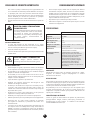
SPECIFICATIONS
Control Pro 130 Power Tank
Maximum Pressure 1600 PSI (11.1 MPa)
Capacity 0.24 GPM (0.91 LPM)
Tank Capacity 1.5 gallon (5.7 l)
Horsepower 0.38
Max. tip 0.015”
Power Requirement 15 amp minimum circuit on 115 VAC,
60 Hz current
Generator power
requirement
2500 Watt (disable idle-down feature)
Overheating
protection
This sprayer has a built-in protective
device to prevent damage from
overheating. The sprayer may
automatically shut down after heavy
use. If this happens, turn switch OFF
(0), unplug the sprayer and allow to
cool for 20-30 minutes and resume
spraying.
CAPABILITY
Sprays a variety of paints (oil-based and latex), primers, stains,
preservatives and other nonabrasive materials.
DO NOT USE!
This pump should not be used with textured materials, block ller,
lacquers, industrial enamels, or asphalt sealer or materials containing
HHC. See coating supplier if ash point is not listed on the container.
Do not spray or clean with liquids having a ash point of less than
38ºC (100ºF). Flash point is the temperature at which a uid can
produce enough vapor to ignite.
SAFETY FEATURES
Spray gun trigger lock and pressure diuser; built-in tip safety guard;
PRIME/SPRAY knob for safe pressure release. Conforms to UL STD
1450. Certied to CSA C22.2 NO 68.

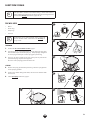
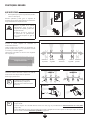
1
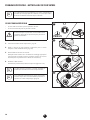
2
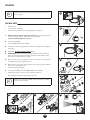
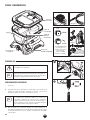
PARTS AND COMPONENTS
6
EN
PRIME
k
SPRAY
p
Spray hose
port
Tank
Inlet lter (A)
ON/OFF
switch
Tank lid
Material
return tube
PRIME/SPRAY
knob (B)
The PRIME/SPRAY
knob can be turned
in either direction to
desired setting
(vertical = PRIME,
horizontal = SPRAY ).
Spray gun
Spray tip
Tip guard
a
b
Washer (a) and
saddle seat (b)
come preassembled
inside the spray guard
Spray hose
A
B
ASSEMBLY
Do not plug in the power cord until assembly is
complete.
i
Remove the plastic cap from the spray hose port and
the plastic plug from the end of the spray hose prior to
assembly.
TOOLS NEEDED
• Two 6” adjustable wrenches
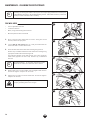
1. Thread one end of the high pressure spray hose to the spray hose
port. Hold the port with an adjustable wrench, and tighten the hose
with the other. Do not over-tighten.
i
If you purchased the accessory hose (sold separately),
make sure to attach this accessory hose rst to the
pump (the same way as step 1, above). Then attach the
hose included with the sprayer to the accessory hose.
2. Spin the gun onto the male tting on the other end of the spray hose.
Turning the gun instead of the hose will make it easier to align the
threads. Tighten the hose end with a wrench.

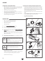
LOCKED
HANDLE
1
0
2
k
3 4
EN
7
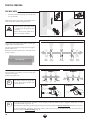
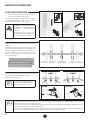
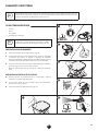
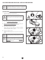
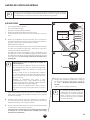
BEFORE YOU BEGIN
i
This section contains instructions that will be repeated
throughout this manual. Read and understand this
section before using the equipment.
SPRAY GUN TRIGGER LOCK
Engage the trigger lock whenever instructed.
The gun is locked when the trigger lock is at a 90º angle (perpendicular to
the trigger in either direction).
MOVING / EMPTYING THE SPRAYER
When lifting the sprayer in order to move it or empty the tank, secure with
both hands the grooved handle area on both sides of the tank.
The sprayer can be heavy when lled with spraying
material. Make sure to lift with your legs and not your
back in order to reduce the risk of injury.
Do not use the tank lid to carry the sprayer as it may slip
o, causing the sprayer to be dropped.
At
tention
Do not use the hose as a strength member to pull or lift
the equipment.
PRESSURE RELIEF PROCEDURE
Be sure to follow the Pressure Relief Procedure when
shutting the unit o for any purpose. This procedure
is used to relieve pressure from the spray hose.
1. Turn the power OFF (0).
2. Lock the spray gun. Turn the PRIME/SPRAY knob to PRIME.
3. Unlock the spray gun. Briey pull the trigger to fully relieve pressure
from the system.
4. Lock the spray gun.

1
PUSH
2
3
k
0
4
A
5
B
0
8
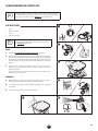
EN
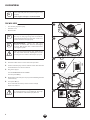
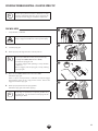
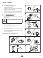
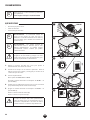
LOAD MATERIAL
i
These steps will prime the system and get it ready
to spray.
www.wagnercontrolpro.com/howtoCP130
YOU WILL NEED
• The material you plan to spray
• Extension cord
• Waste bucket
i
Recommendation: It is good practice to perform
the steps on this page using water to familiarize
yourself with the function of the unit as well as to
ensure the unit is set up properly.
i
Recommendation: Always use new spray
material or material that has been thoroughly
strained. Old material often contains debris that
can clog the system.
At
tention
Take care to prevent material spills. Make sure to
use drop cloths and mask anything that is in the
spraying area and could accidentally be sprayed.
1. Push tab on lter twice to ensure inlet valve operation.
2. Fill the tank with spray material. Pull the return tube from the
tank and hold it over a waste container.
3. Plug in the sprayer.
Turn the PRIME/SPRAY knob to PRIME.
Turn the power ON (l).
4. Allow pump to run until you see spray material owing from the
return tube (A).
5. Turn power OFF (0).
Place return tube back into position over the tank (B).
Replace the tank lid.
At
tention
The tank lid should t snugly over the tank, but it
is not designed to be air- or liquid-tight. Do not tip
the unit when it is lled with spray material.

1
2
0
p
3
4
k
PAGE 7
5
a
b
a
b
OR
6
OR
7
OR
8
p
0
EN
9
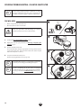
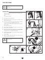
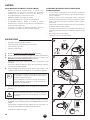
SPRAYING
i
Follow these steps to deliver spray material from the tank to
the spray gun.
YOU WILL NEED
• Waste bucket
• Scrap material / cardboard
• Drop cloths to protect oors and furnishings from overspray
1. Make sure the tip and spray guard are removed. Point the spray gun into
a separate waste container. Unlock the spray gun trigger.
Squeeze and hold trigger for steps 2-3.
2. Turn the power ON (l).
Turn the PRIME/SPRAY knob to SPRAY.
3. Continue to squeeze trigger until the material is owing freely through the
spray gun.
4. Perform the Pressure Relief Procedure, page 7.
5. IMPORTANT: Make sure the washer (a) and saddle seat (b) are installed
in the rear of the spray guard. Note the orientation of the saddle seat (b)
based on the orientation of the spray tip.
6. Make sure the spray gun trigger is locked. Thread the spray tip guard
assembly onto the gun. Tighten by hand.
7. Make sure the spray tip is rotated forward to the spray position, with the
arrow on the tip facing forward.
Unlock the spray gun trigger.
8. Turn the power ON (l). Turn the PRIME/SPRAY knob to SPRAY.
Point the spray gun at a piece of scrap material/cardboard.
Pull the trigger and practice spraying (see page 10).
i
Motor will cycle ON and OFF while spraying to regulate
pressure. This is normal.

CORRECT INCORRECT
10” - 12”
(25 - 30 cm)
CORRECT
10” - 12”
(25 - 30 cm)
INCORRECT
Start
stroke
End
stroke
Pull
trigger
Release
trigger
Move
steadily
i
If the spray pattern becomes distorted or stops spraying completely while the gun is triggered, follow any or all the
procedures listed on pages 11-12.
If you plan to be away from your spray project for more than one hour, follow the Short Term Storage instructions on page 13.
If you have diculty achieving a good spray pattern, your spray tip may not be ideal for the type of material you are
spraying. Refer to Troubleshooting page, 19.
10
EN
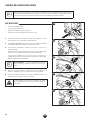
PRACTICE SPRAYING
YOU WILL NEED
• A surface to practice spraying (wood, carboard
or scrap drywall)
While spraying, the spray guard / tip assembly can be
rotated to better suit your spraying motion.
Lock the spray gun trigger prior
to rotating the spray guard / tip
assembly.
Make sure the spray guard nut is
not loosened after rotating.
Flex your wrist as you move in order to keep gun
parallel to the surface.
Hold the spray gun level.
i
The distance from the spray gun
to the spray object should not
exceed 16 inches.
Trigger gun after starting the stroke. Release the
trigger before ending the stroke.
The spray gun should be moving when the trigger is
pulled and released.
Overlap each stroke by about 50%. This will ensure
an even coating.
50% Overlap

1
2
3
p
4
EN
11
SPRAYING TROUBLESHOOTING CLEAR THE SPRAY TIP
i
If the spray pattern becomes distorted or stops
spraying completely while the gun is triggered, the
spray tip could be clogged. Follow the steps below.
YOU WILL NEED
• Scrap material / cardboard
Do not attempt to unclog or clean the tip with your
nger. High pressure uid can cause injection injury.
1. Lock the spray gun.
2. Rotate spray tip 180 degrees from its current position.
i
If spray tip is dicult to rotate, relieve pressure by:
1) slowly turn PRIME/SPRAY knob to PRIME,
2) unlock the spray gun and
3) squeeze trigger while pointing at scrap material/
cardboard.
Release trigger, lock the spray gun, and try rotating
spray tip again.
3. Make sure the PRIME/SPRAY knob is turned to SPRAY.
Unlock the spray gun.
Point at a piece of scrap material / cardboard and squeeze trigger
until material comes out in a high pressure stream. Release the
trigger and lock the spray gun.
4. Rotate spray tip forward to the spray position.
Unlock the spray gun and resume spraying.
i
If tip clogs are persistent, an optional gun lter may
be purchased. See Accessories section (page 58) for
optional gun lters.

1
k
PAGE 7
2
3
4
12
EN
SPRAYING TROUBLESHOOTING CLEAN THE INLET FILTER
i
If the spray pattern becomes distorted or stops
spraying completely while the gun is triggered, the
inlet lter could be clogged. Follow the steps below.
YOU WILL NEED
• Warm, soapy water for latex material
• Mineral spirits for oil based materials
At
tention
Make sure your oors and furnishings are covered
with drop cloths to prevent accidental drips.
1. Perform the Pressure Relief Procedure, page 7.
2. Empty the tank of spray material (see Moving / Emptying the
Sprayer, page 7.
3. Remove inlet lter from tank.
Clean the inlet lter using the appropriate cleaning solution (warm,
soapy water with latex- and water-based materials, mineral spirits
with oil-based paints or stains).
4. Snap the inlet lter back into place.
Resume spraying (follow steps on pages 8-9)
i
If the inlet lter clogs, it is a good idea to strain the
material you are using prior to lling the hopper.
i
If after completing all of the steps in Spraying
Troubleshooting you are still experiencing problems
spraying, refer to the Troubleshooting section (page
19).

1
k
PAGE 7
2
AND
3
4
AND
5 6
PAGE 9
EN
13
i
This procedure should be used when taking a short term break or
when ending your project for the day. If your break is longer than 16
hours follow Cleanup instructions, pages 14-15.
YOU WILL NEED
• Water
• Plastic bag
• Damp rags
• Stir stick
i
Instructions are for latex materials only! If using oil
based material follow instructions for Cleanup on
pages 14-15.
SHUTDOWN
1. Perform the Pressure Relief Procedure, page 7.
2. Turn spray tip 90º. This will prevent air from drying out any spray
material that may be inside the spray tip. Wrap spray tip and guard
in a damp rag and then place entire spray gun in plastic bag.
3. Pour 1/2 cup water slowly on the top of the paint to prevent the
paint from drying. Replace the hopper lid.
Place the entire spraying system out of the sun.
STARTUP
4. Remove the spray gun from the plastic bag. Turn the spray tip back
to the spraying position.
5. If water was added during shut down, stir water into material with
the stir stick.
6. Follow Spraying instructions, page 9.
SHORT TERM STORAGE

1
k
PAGE 7
2
3
4
5
0
p
14
EN
CLEANUP
CLEANING NOTES READ BEFORE CLEANING
• When using latex material, clean sprayer and components with
warm, soapy water. For oil based material use mineral spirits.
Never use mineral spirits with latex materials.
• NEVER use gasoline to clean sprayer.
• Dispose of used cleaning solution properly.
• Thorough cleaning and lubrication of sprayer is important to
ensure proper operation after storage.
• If you ush your sprayer with mineral spirits, repeat Cleanup
instructions using warm, soapy water.
YOU WILL NEED
• Warm, soapy water if using latex material
• Mineral spirits if using oil-based material
• Empty waste container
• Soft-bristled brush
1. Perform Pressure Relief Procedure (page 7).
2. Remove the tip guard from the spray gun.
3. Empty the tank of spray material (see Moving / Emptying the
Sprayer, page 7.
Rinse the tank with the appropriate cleaning solution until clean.
Dispose of the cleaning solution, and then ll the tank again with
NEW cleaning solution.
4. Remove the spray tip from the tip guard. Carefully place both into
the tank full of cleaning solution.
i
Allowing the spray tip and tip guard to soak in the
tank while ushing will make it easier to clean them
afterwards.
Take care not to lose the saddle seat and washer
located inside the rear of the spray guard.
5. Point the spray gun at the side of a waste container.
Ground the gun against the side of a metal waste
container if ushing with mineral spirits.
While squeezing the trigger, turn the sprayer ON (l), and turn the
PRIME/SPRAY knob to SPRAY.
Continue squeezing the trigger until uid is coming out clear.
You may need to get new cleaning solution and repeat.
(Continued on the next page)
FOLLOW THESE STEPS WHENEVER CLEANING WITH MINERAL SPIRITS:
• If spraying or cleaning with oil-based materials, the spray gun
must be grounded while preparing the spray hose or cleaning.
• Ground the gun by holding it against the edge of a metal
container while purging. Failure to do so may lead to a static
electric discharge which may cause a re.
• Always ush spray gun at least one hose length from spray
pump.
• If collecting ushed solvent in one gallon metal container, place
it into an empty ve gallon container, then ush.
• Area must be free from vapors.
• Follow all cleanup instructions.

6
k
7
8
P. 11
9
k
10 11
k
0
12 13
EN
15
CLEANUP CONTINUED
6. Perform Pressure Relief Procedure (page 7).
7. Remove the inlet lter. Clean by hand using a soft-bristled brush.
Snap back into place when clean.
Remove the tip guard and spray tip from the cleaning solution.
Clean by hand using a soft bristled brush.
8. IMPORTANT STEP: Fill the tank with warm, soapy water. Following
steps 5-7 in the “Spraying” section, spray at least one gallon of warm,
soapy water. This will ensure that the spray tip will be completely
clean for the next use.
9. Perform Pressure Relief Procedure (page 7).
10. Remove the spray tip assembly.
Repeat step 5 from above, continuing to squeeze the trigger until
uid comes out clear.
At
tention
Do not allow the pump to run for more than 30
seconds without uid.
11. Turn PRIME/SPRAY knob to PRIME. Turn power OFF.
Replace the spray tip/tip guard assembly.
12. Grip the spray hose tting near the spray gun with a wrench. Loosen
and remove the spray hose from the gun.
13. Place a wrench on the outlet valve to secure it. Using the second
wrench, remove the spray hose.
Hold one end of the spray hose higher than the other and drain
the hose of all cleaning solution into a waste container. Properly
dispose of the cleaning solution.
Move on to the Long Term Storage steps, next page.

1 2
a
3
HOUSEHOLD
OIL
4
5
HOUSEHOLD
OIL
6
0
7
16
EN
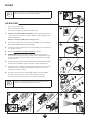
LONG TERM STORAGE
i
Follow these steps to prepare your sprayer for long-
term storage.
YOU WILL NEED
• Light household oil (such as 10W30 motor oil or vegetable oil for
example) / All Guard
• Rags
• Two adjustable wrenches
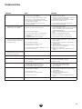
1. Pull trigger guard from gun housing.
2. Tighten the wrench over the wrench ats (a). Unscrew the gun
housing using a wrench.
3. Tip the spray gun upside down and pour a few drops of All Guard
inside the gun housing nut (DO NOT remove the nut).
A light oil can be substituted (such as 10W30 motor oil or vegetable
oil for example).
Reassemble the spray gun.
4. Place a wrench on the outlet valve to secure it. Using the second
wrench, remove the spray hose.
5. Remove the inlet lter. Pour approximately 2 ounces of All Guard
inside the inlet valve housing. A light oil can be substituted (such
as 10W30 motor oil or vegetable oil for example).
6. Cover the outlet valve with a rag. Turn the power ON (l) and let the
pump run for 5 seconds.
Turn power OFF.
7. Replace inlet lter. Wipe entire unit, hose, and spray gun to
remove accumulated spray material.
At
tention
Store the unit indoors with the power cord wrapped
around the base.

1
1
2
3
6
4
5
TAPER
2
7
8
EN
17
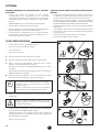
MAINTENANCE CLEANING THE INLET VALVE
i
Cleaning or servicing the inlet valve may be required if the unit has priming problems.
Priming problems may be prevented by properly cleaning the sprayer and following the
long-term storage steps.
YOU WILL NEED
• 8 mm (5/16”) hex wrench
• Needle nose pliers
• Warm, soapy water if using latex material
• Mineral spirits for oil based material
• Household oil (such as 10W30 motor oil or vegetable oil for example)
1. Perform the Pressure Relief Procedure, found in the main instruction
manual, to ensure the pump is shut o and depressurized. Remove
the tank lid.
Remove the inlet lter (1).
Using the lid as a tray for the parts, insert an 8 mm (5/16”) hex wrench
into the hex opening (2) and unscrew the inlet valve tting (2) from
the sprayer.
You may need to use a ball point pen, tweezers, screwdriver, O-ring
pick, and/or needle nose pliers to remove the inlet valve seat (3),
inlet valve ball (4), spring (5), and O-ring (6). A spare spring (5) is
included with your sprayer.
i
Suggestion for removal of the inlet valve assembly
After removing the inlet lter (1) insert an 8 mm (5/16”)
hex wrench into the hex opening (2) and unscrew the inlet
valve tting (2) from the sprayer.
Snap the lid back onto the sprayer, turn it upside down,
and tap the bottom of the sprayer a few times to loosen
the inlet seat (3), ball (4), and spring (5).
With the sprayer still upside down carefully remove the
lid. Be careful not to lose any of the removed parts unless
you plan to replace them instead of clean them.
Flip the sprayer right-side up again and remove the O-ring
(6) with an O-ring pick or tweezers.
Inspect and clean the inlet valve housing area where the inlet valve
assembly was removed with the appropriate cleaning solution.
2. Lubricate the O-ring (7) with household oil and install onto the inlet
tting (8). Lubricate the O-ring (7) once more after it is installed on
the inlet tting.
3. Replace all parts back into the inlet valve housing in the reverse order
of how they were removed.
Note the correct orientation of the inlet valve seat (3). The taper
should be facing downward upon reinstallation.
Replace inlet valve tting (2) by screwing it into the sprayer. Tighten
securely with a 8mm (5/16”) hex wrench. Torque to 50-57 in. lbs (5.5
- 6.5 N.m). Do not overtighten the inlet valve tting.
Replace inlet lter (1).
i
If priming problems persist, you may need
to replace the inlet valve assembly. Call
Technical Service (1-800-328-8251) to
order a new inlet valve assembly.

1
2
3
4
5
18
EN
MAINTENANCE CLEANING THE OUTLET VALVE
i
Cleaning or servicing the outlet valve may be necessary if spray performance remains poor
after following the steps in the Troubleshooting section. Call Technical Service (1-800-328-
8251) to order a new outlet valve assembly.
YOU WILL NEED
• Two 6” adjustable wrenches
• 2.5 mm hex wrench
• Warm, soapy water if using latex material
• Mineral spirits for oil based material
1. Place a wrench on the outlet valve to secure it. Using the second
wrench, remove the spray hose.
2. Loosen (but do not remove) the set screw just underneath the
outlet valve with a 2.5 mm allen wrench.
3. Unscrew outlet valve from outlet valve housing using wrench.
Remove any accumulated material inside outlet valve housing using
appropriate solution for material being used.
Pay particular attention to the ball and seat area at the end of the
outlet valve (opposite the hose end). Remove any accumulated
material.
i
Recommendation: If used with latex-based paints,
ush out the outlet valve with water from a faucet.
4. Replace with new or cleaned outlet valve and tighten with wrench.
Do not over tighten. Torque to 90-110 in-lbs.
5. Tighten the set screw to secure the outet valve. Do not over tighten.
Torque to 20-25 in-lbs.
It is very important to tighten the set screw to ensure
proper grounding of the hose and gun

EN
19
TROUBLESHOOTING
PROBLEM CAUSE SOLUTION
A. The sprayer does not turn on. 1. The sprayer is not plugged in.
2. The sprayer is turned OFF (0).
3. The sprayer shuts o while under pressure.
4. No power is coming from power outlet.
5. The extension cord is damaged or is not the
proper gauge or length.
6. There is a problem with sprayer motor.
7. Spray tip clogged.
1. Plug the sprayer in.
2. Switch the sprayer ON (l).
3. Motor will cycle ON and OFF while spraying to
regulate pressure. This is normal.
4. Reset circuit breaker or nd another outlet.
5. Refer to General Information.
6. Call Technical Service (1-800-328-8251).
7. Refer to Clear the Spray Tip.
B. The sprayer starts but does not
draw material when the PRIME/
SPRAY knob is set to PRIME
1. The inlet valve is stuck from old material.
2. There is no suction at the inlet valve.
3. The inlet lter is clogged.
4. The outlet valve is stuck or contains debris.
5. The inlet valve or outlet valve is worn or
damaged.
6. The PRIME/SPRAY valve is plugged.
1. Push inlet lter tab to release. If still stuck refer
to Cleaning the Inlet Valve.
2. Remove inlet lter and check suction by placing
nger on inlet valve. If no suction, refer to
Cleaning the Inlet Valve.
3. Refer to Clean the Inlet lter or replace the inlet
lter.
4. Refer to Cleaning the Outlet Valve.
5. Replace the inlet valve or outlet valve.
6. Call Technical Service (1-800-328-8251).
C. The sprayer draws material but
the pressure drops when the gun
is triggered (bad spray pattern or
no spray pattern)
1. The spray tip is worn.
2. The inlet lter is clogged.
3. The spray tip is plugged.
4. The material is too heavy or thick.
5. The material is too coarse.
6. The outlet valve assembly is damaged or worn.
7. Spray hose is too long.
1. Replace spray tip with a new one.
2. Refer to Clean the Inlet lter, or replace with a
new inlet lter.
3. Refer to Clear the Spray Tip or replace with a
new spray tip.
4. Thin the material.
5. Strain the material or purchase the accessory
lter (see Accessories, page 58).
6. Replace the outlet valve.
7. Remove any extra hose length that has been
added.
D. The PRIME/SPRAY knob is set to
SPRAY and there is ow through
the material return tube
1. The PRIME/SPRAY valve is dirty or worn. 1. Call Technical Service (1-800-328-8251).
E. The spray gun leaks 1. Internal parts of spray gun are worn or dirty. 1. Call Technical Service (1-800-328-8251).
F. The spray tip assembly leaks 1. The tip guard nut is loose.
2. Tip guard was assembled incorrectly.
3. Tip seal is worn
1. Tighten tip guard nut.
2. Remove and assemble correctly.
3. Replace tip seal
G. The spray gun will not spray 1. The spray tip plugged.
2. The spray tip is in wrong position.
3. PRIME/SPRAY knob not set on SPRAY.
4. Accessory lter is dirty or plugged.
1. Refer to Clear the Spray Tip .
2. Rotate spray tip to SPRAY position.
3. Turn PRIME/SPRAY knob to SPRAY.
4. Clean or replace.
H. The spray pattern is poor (tailing) 1. The spray tip is plugged.
2. The inlet lter is clogged.
3. The spray tip is worn.
4. The material is too heavy or thick.
5. Spray hose is too long.
2. Refer to Clear the Spray Tip
3. Refer to Clean the Inlet lter or replace with a
new inlet lter.
4. Replace the spray tip.
5. Thin material per manufacturer’s
recommendations.
5. Remove any extra hose length that has been
added.
I. The spray tip will not turn 1. High pressure has locked the spray tip in place. 1. Refer to Clear the Spray Tip.

20
F
CONSIGNES DE SÉCURITÉ IMPORTANTES
TABLE DE MATIÈRES
CONSIGNES DE SÉCURITÉ IMPORTANTES ____________ 2022
Explication des symboles utilisés _______________________ 20
Directives de mise à la terre ____________________________ 21
Renseignements importants sur l’électricité_______________ 21
Dangers pour la sécurité ___________________________ 21-22
RENSEIGNEMENTS GÉNÉRAUX ________________________ 23
Specications _______________________________________ 23
PIÈCES ET COMPOSANTS ______________________________ 24
Assemblage ________________________________________ 24
AVANT DE COMMENCER ______________________________ 25
Verrou de détente ___________________________________ 25
Procédure de décompression __________________________ 25
Déplacer / vider le pulérisateur _________________________ 25
REMPLISSEZ DE MATIÈRE LIQUIDE _____________________ 26
PULVÉRISATION _____________________________________ 27
EXERCICES DE PULVÉRISATION ________________________ 28
PROBLÈMES POTENTIELS __________________________ 2930
Désobstruction de l’embout ___________________________ 29
Nettoyage du ltre d’entré ____________________________ 30
RANGEMENT À COURT TERME _________________________ 31
NETTOYAGE ______________________________________ 3233
RANGEMENT À LONG TERME __________________________ 34
ENTRETIEN _______________________________________ 3536
Nettoyage de la soupape de d’entrée ____________________ 35
Nettoyage de la soupape de sortie ______________________ 36
DÉPANNAGE _________________________________________ 37
LISTE DE PIÈCES ___________________________________ 5658
GARANTIE ___________________________________________ 59
EXPLICATION DES SYMBOLES UTILISÉS
Lire toutes ces consignes avant d’utiliser l’appareil. Garder ces
consignes.
Pour réduire les risques d’incendie ou d’explosion, de choc électrique
et de blessure, vous devez lire et comprendre les directives
gurant dans ce manuel. Familiarisez-vous avec les commandes et
l’utilisation adéquate de l’équipement.
Ce symbole indique un risque potentiel
pouvant entraîner des blessures graves ou
même mortelles. Vous trouverez ci-après
d’importantes consignes de sécurité.
Attention
Ce symbole indique un risque potentiel
pour vous ou pour l’appareil. D’importantes
informations sur la manière d’éviter tout
dommage de l’équipement ou d’éviter des
blessures légères sont indiquées ci-après.
Danger de blessure par injection de produit
Danger d’incendie
Risque d’explosion
Vapeurs toxiques et/ou inammables.
Danger d‘intoxication et de brûlure
Risque de décharge électrique
i
Les notes contiennent des informations qui
doivent être consciencieusement respectées.
Le Control Pro peut être utilisé uniquement avec les
embouts, les tuyaux ou les pistolets de pulvérisation
compatibles avec le Control Pro. N’utilisez pas
d’accessoires non compatibles avec le Control Pro
pour ce système.
La page est en cours de chargement...
La page est en cours de chargement...
La page est en cours de chargement...
La page est en cours de chargement...
La page est en cours de chargement...
La page est en cours de chargement...
La page est en cours de chargement...
La page est en cours de chargement...
La page est en cours de chargement...
La page est en cours de chargement...
La page est en cours de chargement...
La page est en cours de chargement...
La page est en cours de chargement...
La page est en cours de chargement...
La page est en cours de chargement...
La page est en cours de chargement...
La page est en cours de chargement...
La page est en cours de chargement...
La page est en cours de chargement...
La page est en cours de chargement...
La page est en cours de chargement...
La page est en cours de chargement...
La page est en cours de chargement...
La page est en cours de chargement...
La page est en cours de chargement...
La page est en cours de chargement...
La page est en cours de chargement...
La page est en cours de chargement...
La page est en cours de chargement...
La page est en cours de chargement...
La page est en cours de chargement...
La page est en cours de chargement...
La page est en cours de chargement...
La page est en cours de chargement...
La page est en cours de chargement...
La page est en cours de chargement...
La page est en cours de chargement...
La page est en cours de chargement...
La page est en cours de chargement...
La page est en cours de chargement...
-
 1
1
-
 2
2
-
 3
3
-
 4
4
-
 5
5
-
 6
6
-
 7
7
-
 8
8
-
 9
9
-
 10
10
-
 11
11
-
 12
12
-
 13
13
-
 14
14
-
 15
15
-
 16
16
-
 17
17
-
 18
18
-
 19
19
-
 20
20
-
 21
21
-
 22
22
-
 23
23
-
 24
24
-
 25
25
-
 26
26
-
 27
27
-
 28
28
-
 29
29
-
 30
30
-
 31
31
-
 32
32
-
 33
33
-
 34
34
-
 35
35
-
 36
36
-
 37
37
-
 38
38
-
 39
39
-
 40
40
-
 41
41
-
 42
42
-
 43
43
-
 44
44
-
 45
45
-
 46
46
-
 47
47
-
 48
48
-
 49
49
-
 50
50
-
 51
51
-
 52
52
-
 53
53
-
 54
54
-
 55
55
-
 56
56
-
 57
57
-
 58
58
-
 59
59
-
 60
60


WAGNER Control Pro 130 Power Tank Le manuel du propriétaire
- Catégorie
- Pulvérisateur de peinture
- Taper
- Le manuel du propriétaire
dans d''autres langues
Documents connexes


Autres documents
-
Titan 740IX Le manuel du propriétaire
-
-
-
Titan Advantage EXP2155 Le manuel du propriétaire
-
-
-
-
-
 Asphalt Kingdom PowrLiner 850 Guide de démarrage rapide
