La page est en cours de chargement...

Installation Guide
HORT145 | A-1027542
Life2
LED Lighting System
BEFORE YOU BEGIN
Read these instructions completely and carefully.
For the latest North American install guides for your product go to: www.LED.com/hort
For the latest European install guides for your product go to: www.LED.com/hort
The light source of this luminaire is not replaceable; when the
light source reaches its end of life the whole luminaire shall be
replaced.
The external flexible cable or cord of this luminaire can not
be replaced; if the cord is damaged, the luminaire shall be
destroyed.
Prepare Electrical Wiring
FOR UL ONLY
Electrical Requirements
• Acceptable for use in dry, damp and wet locations.
• Follow all National Electric Codes (NEC) and local codes.
Save These Instructions
Use only in the manner intended by the manufacturer.
If you have any questions, contact the manufacturer.
This device complies with Part 15 of the FCC Rules. Operation
is subject to the following two conditions: (1) This device may
not cause harmful interference, and (2) this device must accept
any interference received, including interference that may cause
undesired operation.
CAN ICES-005 (A) / NMB-005 (A)
Note: This equipment has been tested and found to comply with the
limits for a Class A digital device, pursuant to part 15 of the FCC Rules.
These limits are designed to provide reasonable protection against
harmful interference when the equipment is operated in a commercial
environment. This equipment generates, uses, and can radiate radio
frequency energy and, if not installed and used in accordance with
the instruction manual, may cause harmful interference to radio
communications. Operation of this equipment in a residential area
is likely to cause harmful interference in which case the user will be
required to correct the interference at his own expense.
EN
DA Den danske version af installationsvejledningen
og sikkerhedsoplysninger kan findes på følgende
placering: www.LED.com/hort
DE Die deutsche Version der Installationsanleitung und
Sicherheitsinformationen finden Sie in folgendem
Verzeic: www.LED.com/hort
ES La versión española de las instrucciones de
instalación y la información sobre seguridad puede
encontrarse en la siguiente ubicación: www.LED.
com/hort
FI Asennusohjeiden ja turvallisuustietojen
suomenkielinen versio löytyy seuraavasta paikasta:
www.LED.com/hort
FR La version française des instructions d’installations
et information de sécurité est disponible à l’adresse
suivante: www.LED.com/hort
HU A telepítési útmutató és a biztnosági információk
magyar nyelvű változata az alábbi címen található:
www.LED.com/hort
IT La versione italiana del manuale di installazione
e sicurezza può essere reperita nella seguente
sezione: www.LED.com/hort
LT Lietuvišką diegimo instrukcijos ir saugos
informacijos versiją galima rasti šioje vietoje: www.
LED.com/hort
NL De Nederlandse versie van de installatie-instructies
en veiligheidsinformatie kan op de volgende locatie
worden gevonden: www.LED.com/hort
NO Den norske versjonen av installasjonsinstruksjonene
og sikkerhetsinformasjonen er tilgjengelig på: www.
LED.com/hort
PL Polską wersję instrukcji instalacji oraz informacje
dotyczące bezpieczeństwa można znaleźć w
następującej lokalizacji: www.LED.com/hort
PT A versão em Português das instruções de
instalação e das informações de segurança pode
ser encontrada na seguinte localização: www.LED.
com/hort
SV Ni hittar den svenska versionen
av installationsanvisningarna och
säkerhetsinformationen på följande plats: www.LED.
com/hort
LED.com
© 2023 Current Lighting Solutions, LLC. All rights reserved. GE and the GE monogram are trademarks of the
General Electric Company and are used under license. Information and specifications subject to change
without notice. All values are design or typical values when measured under laboratory conditions.
(Rev 06/20/23)
HORT145 | A-1027542
Page 1 of 12

Arize® Life2 Installation Guide
Please contact support at [email protected] with regard to applications other than horizontal. In these applications, luminaires should not be
directly interconnected and the male connector (power input) should be in the upward orientation with the female end facing down.
Electrical products must not be thrown out with domestic
waste. They must be taken to a communal collecting point
for environmentally friendly disposal in accordance with
local regulations. Contact your local authorities or stockist
for advice on recycling. The packaging material is recyclable.
Dispose of the packaging in an environmentally friendly
manner and make it available for the recyclable material
collection-service.
Conforms to the following standards:
IP66 rated
RISK GROUP 1 - CAUTION / ATTENTION - RAYONNEMENT LUMINEUX GROUPE 1
RISK GROUP 2 - CAUTION / ATTENTION - RAYONNEMENT LUMINEUX GROUPE 2*
Possibly hazardous optical radiation emitted from this product. Do not stare at operating lamp. May be harmful to the eyes.
Le rayonnement lumineux émis par ce produit est potentiellement dangereux. Ne pas regarder la lumière émise directement car elle
pourrait occasionner des dommages aux yeux.
WARNING / AVERTISSEMENT
RISK OF ELECTRIC SHOCK
• Turn power off before inspection, installation or removal.
• The electrical supply for each luminaire must always be
connected to the male connector.
• Not to be submerged or used in a marine environment.
RISK OF FIRE
• Follow all local codes.
RISQUES DE DÉCHARGES ÉLECTRIQUES
•Coupez l’alimentation avant l’inspection, l’installation ou le déplacement.
• L’alimentation électrique pour chacun des luminaires doit toujours
être branché du côté mâle de la prise.
• Ne pas submerger ou installer dans un environnement marin.
RISQUES D’INCENDIE
• Respectez tous les codes locaux.
Visit LED.com
*See table below for risk groups by model.
IEC 62471
UL Only IEC 62778
CE/UKCA Only
Part Number Risk Group Risk Group Min viewing
distance (mm)
GEHL48HPPR3 RG2 (Lb,Eb) RG1 N/A
GEHL48HPPB3 RG2 (Lb) RG2 447
GEHL48HPKR3 RG1 RG1 N/A
GEHL48HPPF3 RG2 (Eb) RG2 352
GEHL48HPKB3 RG1 RG2 390
GEHL48HPKF3 RG1 RG1 N/A
GEHL48HBRI3 RG1 RG2 359
GEHL48HBRV3 RG1 RG2 420
GEHL48HPPV3 RG2 (Eb) RG2 530
GEHL96HPPR3 RG0 RG2 325
GEHL96HPPB3 RG2 (Eb, Lb) RG2 432
GEHL96HPKR3 RG0 RG2 257
GEHL96HPKB3 RG1 RG2 390
GEHL96HPPV3 RG2 (Eb, Lr) RG2 482
These photobiological safety markings are based on testing of
the light output characteristic of a single horticultural luminaire.
Increased exposure risk to facility personnel may be present
depending upon the number of horticultural luminaires and their
placement and/or positioning within the plant growth facility.
It is the responsibility of the plant growth facility to address
these risks at the facility level and to ensure that people entering
the plant growth areas while the lights are on, are aware of these
risks and that appropriate safeguards are in place.
Manufacturer:
Current Lighting Solutions LLC, 1975 Noble Road, Cleveland, Ohio 44112 USA
Importer:
UK: Current Lighting Limited, 3rd Floor, 1 Ashley Road, Altrincham, UK, WA14 2DT
EU: Current Netherlands B.V., Programmeurstraat 6, 1033MT Amsterdam, Netherlands
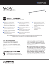
Suitable for operation in an ambient temperature
between 32°F (0°C) and 104°F (40°C).
A mechanical ventilation or cooling system is required to
maintain the temperature within the growing space below
104°F (40°C) when the light module is in operation.
Opération compatible avec un environnement à temperature
ambiante controlée entre 32°F (0°C) et 104°F (40°C).
l’utilisation d’un système de contrôle de la température sera
nécessaire pour garder la serre sous les 104°F (40°C) lorsque
le luminaire est en function.
0°C
40°C
LED.com
© 2023 Current Lighting Solutions, LLC. All rights reserved. GE and the GE monogram are trademarks of the
General Electric Company and are used under license. Information and specifications subject to change
without notice. All values are design or typical values when measured under laboratory conditions.
(Rev 06/20/23)
HORT145 | A-1027542
Page 2 of 12

Wire stripper/cutter
Screwdriver
Cordless drill with
driver bit
Arize Life² fixtures (4 ft. or 8 ft.)
Cable Accessories (GECAaabcc-deffg), see page 7
Optional - Jumper cable (93138395 – 2ft, with dimming wire)
Mounting clips (88818 – standard) or (10734 – slim)
#10 (M5) self-tapping flathead screws
Approved 18-14 AWG (0.82-2.08 mm2) wire connectors, in-line splice connectors or
alternative approved connectors.
End cap for connectors
Optional - Cable clamps
Tools Required Components Required
Arize® Life2 Installation Guide
Luminaire length Minimum spacing / Leader cable length
4 ft. 47.3” (120 cm) 0.2" (5 mm) / 23.6" (600 mm)
8 ft. 95” (240 cm) 0.2" (5 mm) / 23.6" (600 mm)
Mounting Surface
Product Length
1
1
A A
B
2
2
3
1
2
3
3
4 5 6
1
2
3
4
5
6
7
8
7 8
A B
LED.com
© 2023 Current Lighting Solutions, LLC. All rights reserved. GE and the GE monogram are trademarks of the
General Electric Company and are used under license. Information and specifications subject to change
without notice. All values are design or typical values when measured under laboratory conditions.
(Rev 06/20/23)
HORT145 | A-1027542
Page 3 of 12

Arize® Life2 Installation Guide
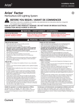
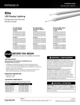
Place the luminaire on the surface with the
male connector oriented towards the intended
electrical supply.
If not already covered, insert an end cap into the
female connector, and twist the end cap clockwise to
secure.
Go to METHOD 3 on page 7
Rotate and Push
1
2
SNAP!
SNAP!
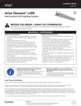
Mounting instructions using Current’s standard and slim mounting clips.
Press the luminaire into its mounting clips so that
the male connector is oriented towards the intended
electrical supply. TIP: Align luminaire on one side of
the mounting clips; then rotate the luminaire until it
snaps into other side of the mounting clips.
(Only for single luminaire installation)
Alternately: The required mounting clips may first
be pressed onto the luminaire, then the luminaire
mounting clip assembly may be mounted on to the
mounting surface using two #10 (M5) self-tapping
flathead screws per mounting clip.
Secure each luminaire mounting clip to a rigid flat
mounting surface using two #10 (M5) self-tapping
flathead screws along the intended run of luminaire.
To avoid stress and damage to luminaire the
entire mounting surface should be flat and the
mounting clips be properly aligned. Refer to table
on page 11 for required number of mounting clips
per luminaire.
Align using chalk line,
laser projector or similar
Before starting:
Luminaires must only be mounted using Current’s standard or slim mounting clips (see Components Required on page 3).
METHOD 1
Single Luminaire Installation
12
34
Male connector towards
electrical supply
LED.com
© 2023 Current Lighting Solutions, LLC. All rights reserved. GE and the GE monogram are trademarks of the
General Electric Company and are used under license. Information and specifications subject to change
without notice. All values are design or typical values when measured under laboratory conditions.
(Rev 06/20/23)
HORT145 | A-1027542
Page 4 of 12

Arize® Life2 Installation Guide
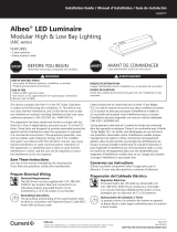
METHOD 2
Directly Interconnected Luminaires
Before starting:
See Multiple Bar Installation Details to ensure you won't exceed the maximum run length per leader cable.
Luminaires must only be mounted using Current’s standard or slim mounting clips (see Components Required on page 3).
Linear Layout
Parallel Layout
Press the luminaire into its mounting clips so that
the male connector is oriented towards the intended
electrical supply. TIP: Align luminaire on one side of the
mounting clips, then rotate the luminaire until it snaps
into other side of the mounting clips.
Secure each luminaire mounting clip to a rigid flat
mounting surface using two #10 (M5) self-tapping
flathead screws along the intended run of luminaire.
To avoid stress and damage to luminaire the entire
mounting surface should be flat and the mounting
clips properly aligned. Refer to table on page 8 for
the required number of mounting clips per luminaire.
Align using chalk line, laser projector or similar
12
NOTE: the recommended distance between two ends should be no more than 0.8" (20mm) for better optical uniformity.
NOTE: the
recommended
maximum space between parallel luminaires is 10" (245mm) for better optical uniformity.
Align using chalk line, laser projector or similar
Male connector towards electrical supply
Rotate and Push
SNAP!SNAP!SNAP! SNAP!SNAP!SNAP!
1A
2A
SNAP!
SNAP!
SNAP!
SNAP!
SNAP!
SNAP!
SNAP!
SNAP!
Male connector towards electrical supply End cap
LED.com
© 2023 Current Lighting Solutions, LLC. All rights reserved. GE and the GE monogram are trademarks of the
General Electric Company and are used under license. Information and specifications subject to change
without notice. All values are design or typical values when measured under laboratory conditions.
(Rev 06/20/23)
HORT145 | A-1027542
Page 5 of 12

Arize® Life2 Installation Guide
Optional: Secure the cables using the optional cable
clamp accessory.
Insert an end cap into the female connector on
the last luminaire in the run, and twist the end cap
clockwise to secure.
Remove end cap from the female connector. Insert
the male connector to the female connector. Make
sure the connector is fully engaged as indicted by
hearing a click.
Use a jumper cable to connect luminaires if the
distance between them is too long.
CLICK!
3A
3C
3B
4
METHOD 2
Directly Interconnected Luminaires
Go to METHOD 3 on page 7
1
2
LED.com
© 2023 Current Lighting Solutions, LLC. All rights reserved. GE and the GE monogram are trademarks of the
General Electric Company and are used under license. Information and specifications subject to change
without notice. All values are design or typical values when measured under laboratory conditions.
(Rev 06/20/23)
HORT145 | A-1027542
Page 6 of 12

Arize® Life2 Installation Guide
IMPORTANT GUIDELINES / CONSEILS IMPORTANTS
• Cables shall not be concealed or extended through a
wall, floor, ceiling, or other parts of the building structure;
located above a suspended ceiling or dropped ceiling;
permanently affixed to the building structure.
• Cables shall be routed so that they are not subject to strain
and are protected from physical damage; visible over their
entire length; and used within their rated ampacity as
determined for the maximum temperature of the installed
environment specified in the instructions.
• Before applying power, ensure that any open female
connectors in the installation are sealed with an end cap.
(see Method 1, step 4)
• Les câbles ne doivent pas être cachés à l’intérieur ou passer
à travers un mur, un plancher, un plafond ou d’autres
parties de la structure du bâtiment; ne doivent pas être
placés au-dessus d’un plafond suspendu; ne doivent pas
faire partie intégrante de la structure du bâtiment.
• Les câbles doivent être installés de façon à être protégés
contre l’étirement et tout autre dommage; être visibles sur
toute leur longueur; utilisés dans la limite de leur capacité
électrique, déterminée pour les limites de température de
l’environnement spécifiée dans ce document.
• Avant de mettre sous tension, assurez-vous que les
connecteurs femelles ouverts du système sont scellés avec
une butée de gaine. (consulter méthode 1, étape 4).
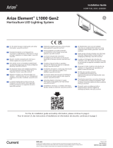
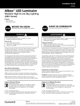
Inside the junction box, connect
the line and neutral wires of the
AC supply source to the line
(black or brown) and neutral
(white or blue) wires of the
leader cable using suitable wire
nuts. If 0-10V dimming will not
be used, cap the dimming wires
(purple and pink*) with suitable
wire nuts. Do not connect the
dimming wires together or to
line, neutral, or ground. If 0-10V
dimming will be used, proceed
to Step 4.
Connect the DIM + (purple) to
the incoming dimmer circuit +.
Connect the Dim – (pink*) to the
incoming dimmer circuit –.
Warning: The class 2 0-10V
dimming circuit must be separated
from the AC circuit as required by
the applicable electric code.
Strain relief
0-10V conduit
AC conduit
Insert lead wire into junction box.
Insert the female connector of the leader cable so that it fully engages
the male connector of the first luminaire in the run as indicated by
hearing a click.
NOTE: the male connector can be cut o if there is no leader cable.
See Multiple Bar Installation Details to not exceed maximum run
length for one leader.
To avoid damage, do not bend or otherwise exert excessive force
on the connector during installation.
See Components Required on page 3 for leader cable part number.
42
1
3
METHOD 3
Wiring Connections
Leader cable
to luminaire(s)
Purple (Dim+)
Pink (Dim-)
Black or brown (L)
White or blue (N)
0-10V
Dimmer
120-277V
AC Supply
CLICK!
For UL Only
* 2021 and earlier: purple and gray
2022 and later: purple and pink
LED.com
© 2023 Current Lighting Solutions, LLC. All rights reserved. GE and the GE monogram are trademarks of the
General Electric Company and are used under license. Information and specifications subject to change
without notice. All values are design or typical values when measured under laboratory conditions.
(Rev 06/20/23)
HORT145 | A-1027542
Page 7 of 12

Arize® Life2 Installation Guide
METHOD 3
M19 Cable Accessories
M19 Splitter
M19 Jumper
(optional)
M19 Leader
(see Wiring Connections) M19 18AWG Leader Cable
GEHL48Hxxx3 < 14@120V, 20@208V, 26@240V, 26@277V;
GEHL96Hxxx3 < 7@120V, 10@208V, 13@240V, 13@277V
M19 Female
SJOW
18AWG*2
NEMA Plug 5-15P L7-15P L6-20P L7-20P
NEMA Receptacle 5-15R L7-15R L6-20R L7-20R
METHOD 3
M19 Cable Accessories Installation Example
Accessory Type SKU Model Description
M19 Leader Cable (NA) 93142247 GECA30A18-CC10B 10ft (3.0m) Leader with dimming
M19 Leader Cable (EU/UK)
93142232 GECA30A18-BB06B 6ft (1.8m) Leader
93142234 GECA30A18-BB10B 10ft (3.0m) Leader
93142246 GECA30A18-BC06B 6ft (1.8m) Leader with dimming
93142248 GECA30A18-BC10B 10ft (3.0m) Leader with dimming
M19 Leader Cable with Plug (NA)
93142249 GECA30A18-CD06B 6ft (1.8m) Leader with 5-15P Plug
93142250 GECA30A18-CE06B 6ft (1.8m) Leader with L6-20P Plug
93148137 GECA30A18-CP06B 6ft (1.8m) Leader with L7-15P plug
93142251 GECA30A18-CK06B 6ft (1.8m) Leader with L7-20P Plug
M19 Jumper (NA/EU/UK) 93142252 GECA30A18-CF02B 2ft (0.6m) Jumper with dimming
M19 Splitter (NA/EU/UK) 93142256 GECA30A14-CI04B 4ft (1.2m) Splitter with 1 M19 male to 5
M19 female connectors with dimming.
LED.com
© 2023 Current Lighting Solutions, LLC. All rights reserved. GE and the GE monogram are trademarks of the
General Electric Company and are used under license. Information and specifications subject to change
without notice. All values are design or typical values when measured under laboratory conditions.
(Rev 06/20/23)
HORT145 | A-1027542
Page 8 of 12

Arize® Life2 Installation Guide
METHOD 3
M25 Cable Accessories
METHOD 3
M25 Cable Accessories Installation Example A
Accessory Type SKU Model Description
M25 Leader (EU/UK) 93142254 GECA30A14-BG06B 6ft (1.8m) Leader with dimming, 15A, EU
M25 Jumper (NA/EU/UK) 93142255 GECA30A14-CH02B 2ft (0.6m) Jumper with dimming
M25 Splitter (NA/EU/UK) 93142257 GECA30A14-CJ08B 8ft (2.4m) Splitter with 1 M25 male to 5
M19 female connectors with dimming.
M25 Leader (NA) 93142253 GECA30A14-CG06B 6ft (1.8m) Leader with dimming, 15A, NA
GEHL48Hxxx3 Max 14@120V, 20@208V, 26@240V, 26@277V;
GEHL96Hxxx3 Max 7@120V, 10@208V, 13@240V, 13@277V
M25 Splitter
M25 Jumper
(optional)
M25 Leader
(see Wiring Connections) GEHL48Hxxx3 max 38@120V, 65@208V, 72@240V, 83@277V;
M25 14AWG Leader Cable
M19 18AWG Leader Cable
GEHL96Hxxx3 max 19@120V, 32@208V, 36@240V, 41@277V
LED.com
© 2023 Current Lighting Solutions, LLC. All rights reserved. GE and the GE monogram are trademarks of the
General Electric Company and are used under license. Information and specifications subject to change
without notice. All values are design or typical values when measured under laboratory conditions.
(Rev 06/20/23)
HORT145 | A-1027542
Page 9 of 12

Arize® Life2 Installation Guide
METHOD 3
M25 Cable Accessories Installation Example B
GEHL48Hxxx3
38@120V,
65@208V,
72@240V,
83@277V;
GEHL96Hxxx3
19@120V,
32@208V,
36@240V,
41@277V
M19 18AWG Leader Cable
GEHL48Hxxx3 max 14@120V, 20@208V, 26@240V, 26@277V;
GEHL96Hxxx3 max 7@120V, 10@208V, 13@240V, 13@277V
M19 Splitter *5
M19 Jumper (optional)
M25 Splitter
M25 Jumper (optional)
M25 Leader
M25 14AWG
Leader Cable
LED.com
© 2023 Current Lighting Solutions, LLC. All rights reserved. GE and the GE monogram are trademarks of the
General Electric Company and are used under license. Information and specifications subject to change
without notice. All values are design or typical values when measured under laboratory conditions.
(Rev 06/20/23)
HORT145 | A-1027542
Page 10 of 12

Arize® Life2 Installation Guide
Multiple Bar Installation Details
Input voltage : 120VAC - 277VAC, 50/60Hz
Troubleshooting
Symptom Solution
All LED fixtures
are not
illuminated
• Check leader cable connection and/or check circuit breaker.
• Check plug connectors on the LED fixtures for improper connections or short circuits.
• Ensure leader cable is securely connected to the female plug connector on the first LED luminaire.
Some LED
fixtures are not
illuminated
• Check plug connectors on the LED fixtures for improper connections or short circuits.
• Ensure any jumper cables are securely connected between the male/female plug connectors
of the LED fixtures.
GEHLxxHyyz3
*Key for xx: 48=48 in., 96=96 in.
*Key for yy: PP=Purple, PK=Pink, BR=Broad Spectrum
*Key for z: Type "R", "B", "V", "I", "F"
Product Codes
Lamp
Length
Product
Code (SKU)
Description
Code
Maximum Bars
Per M25 14AWG Leader Cable
Maximum Bars
Per Interconnected run or
M19 18AWG Leader Cable
Qty of
Mounting
Clips
Electrical Loading Detail
Typical Current (A)
For
120VAC
For
208VAC
For
230VAC
For
277VAC
For
120VAC
For
208VAC
For
230VAC
For
277VAC
Plastic
Clips
Metal
Clips
For
120VAC
For
208VAC
For
230VAC
For
277VAC
4 ft.
93137762 GEHL48HPPR3
38 65 72 83 14 20 26 26 2 2 0.30 0.17 0.16 0.14
93137763 GEHL48HPPF3
93137764 GEHL48HPPB3
93137765 GEHL48HPPV3
93137936 GEHL48HPKR3
93137937 GEHL48HPKF3
93137938 GEHL48HPKB3
93137939 GEHL48HBRI3
93137940 GEHL48HBRV3
8 ft.
93137941 GEHL96HPPR3
19 32 36 41 7 10 13 13 3 2 0.60 0.34 0.32 0.28
93137942 GEHL96HPPB3
93137943 GEHL96HPPV3
93137944 GEHL96HPKR3
93137945 GEHL96HPKB3
LED.com
© 2023 Current Lighting Solutions, LLC. All rights reserved. GE and the GE monogram are trademarks of the
General Electric Company and are used under license. Information and specifications subject to change
without notice. All values are design or typical values when measured under laboratory conditions.
(Rev 06/20/23)
HORT145 | A-1027542
Page 11 of 12

Arize® Life2 Installation Guide
Unscrew the mounting clips to completely
remove the luminaire.
To insert a new luminaire, see Method 2.
To avoid damage, do not bend or
otherwise exert excessive force on the
connector during installation.
Using a screwdriver, gently pry the luminaire
out of the mounting clips.
Standard Clips Slim Clips
METHOD 4
Replacement Instructions for Directly Interconnected Luminaires
Disconnect the connector on both sides of the luminaire.
Twist
Luminaire to
be replaced
Pull apart
2B2A
3
1
LED.com
© 2023 Current Lighting Solutions, LLC. All rights reserved. GE and the GE monogram are trademarks of the
General Electric Company and are used under license. Information and specifications subject to change without
notice. All values are design or typical values when measured under laboratory conditions.
(Rev 06/20/23)
HORT145 | A-1027542
Page 12 of 12
/