Thermo Fisher Scientific SC20 Suppressor Controller Mode d'emploi
- Taper
- Mode d'emploi

SC20 SUPPRESSOR CONTROLLER
INSTALLATION AND OPERATION
INSTRUCTIONS
© 2001 Dionex Corporation
Document No. 031768
Revision 04
September 2001

©2001 by Dionex Corporation
All rights reserved worldwide.
Printed in the United States of America.
This publication is protected by federal copyright law. No part of this publication
may be copied or distributed, transmitted, transcribed, stored in a retrieval system, or
transmitted into any human or computer language, in any form or by any means,
electronic, mechanical, magnetic, manual, or otherwise, or disclosed to third parties
without the express written permission of Dionex Corporation, 1228 Titan Way,
Sunnyvale, California 94088-3603 U.S.A.
DISCLAIMER OF WARRANTY AND LIMITED WARRANTY
THIS PUBLICATION IS PROVIDED “AS IS” WITHOUT WARRANTY OF
ANY KIND. DIONEX CORPORATION DOES NOT WARRANT,
GUARANTEE, OR MAKE ANY EXPRESS OR IMPLIED
REPRESENTATIONS REGARDING THE USE, OR THE RESULTS OF THE
USE, OF THIS PUBLICATION IN TERMS OF CORRECTNESS,
ACCURACY, RELIABILITY, CURRENTNESS, OR OTHERWISE.
FURTHER, DIONEX CORPORATION RESERVES THE RIGHT TO REVISE
THIS PUBLICATION AND TO MAKE CHANGES FROM TIME TO TIME IN
THE CONTENT HEREINOF WITHOUT OBLIGATION OF DIONEX
CORPORATION TO NOTIFY ANY PERSON OR ORGANIZATION OF
SUCH REVISION OR CHANGES.
TRADEMARKS
Atlas™ Electrolytic Suppressor is a trademark and PeakNet® and SRS® Self-
Regenerating Suppressor are registered trademarks of Dionex Corporation.
VELCRO® is a registered trademark of Velcro Industries B.V.
PRINTING HISTORY
Revision 01, March 2001
Revision 02, April 2001
Revision 03, July 2001
Revision 04, September 2001

Doc. 031768-04 9/01 i
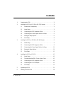
Contents
1. Unpacking the SC20 . . . . . . . . . . . . . . . . . . . . . . . . . . . . . . . . . . . . . . . . 2
2. Installing the SC20 in a DX-320 or DX-320J System . . . . . . . . . . . . . . 2
2.1 Moduleware Compatibility . . . . . . . . . . . . . . . . . . . . . . . . . . . . . 2
2.2 Initial Setup . . . . . . . . . . . . . . . . . . . . . . . . . . . . . . . . . . . . . . . . 2
2.3 Connecting the SC20 Suppressor Cable . . . . . . . . . . . . . . . . . . . 3
2.4 Connecting the Control Input Cable to the Pump . . . . . . . . . . . 5
2.5 Setting the Pump Options . . . . . . . . . . . . . . . . . . . . . . . . . . . . . . 6
2.6 Final Setup . . . . . . . . . . . . . . . . . . . . . . . . . . . . . . . . . . . . . . . . . 8
3. Installing the SC20 in a DX-500 or DX-600 System . . . . . . . . . . . . . . . 9
3.1 Initial Setup . . . . . . . . . . . . . . . . . . . . . . . . . . . . . . . . . . . . . . . . 9
3.2 Connecting the SC20 Suppressor Cable . . . . . . . . . . . . . . . . . . . 9
3.3 Connecting the Control Input Cable to the Pump . . . . . . . . . . 12
3.4 Setting the Pump Options . . . . . . . . . . . . . . . . . . . . . . . . . . . . . 13
3.5 Final Setup . . . . . . . . . . . . . . . . . . . . . . . . . . . . . . . . . . . . . . . . 15
4. Installing the SC20 in a DX-120 . . . . . . . . . . . . . . . . . . . . . . . . . . . . . . 16
4.1 Initial Setup . . . . . . . . . . . . . . . . . . . . . . . . . . . . . . . . . . . . . . . 16
4.2 Disconnecting the SRS A Power Source Cable . . . . . . . . . . . . 16
4.3 Connecting the SC20 Suppressor Cable . . . . . . . . . . . . . . . . . . 18
4.4 Connecting the DX-120 Adapter . . . . . . . . . . . . . . . . . . . . . . . 19
4.5 Final Setup . . . . . . . . . . . . . . . . . . . . . . . . . . . . . . . . . . . . . . . . 21
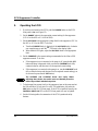
5. Operating the SC20 . . . . . . . . . . . . . . . . . . . . . . . . . . . . . . . . . . . . . . . . 22
6. Shutting Down the SC20 . . . . . . . . . . . . . . . . . . . . . . . . . . . . . . . . . . . . 24


Doc. 031768-04 9/01 1
SC20 Suppressor Controller
Installation and Operation
The SC20 Suppressor Controller is the external power supply required when the
Atlas™ Electrolytic Suppressor (AES) is installed in a DX-320, DX-500, or
DX-600 system, or in a DX-120 Ion Chromatograph. If desired, the SC20 can also
be used with an SRS® Self-Regenerating Suppressor.
This manual provides detailed instructions for installing and operating the SC20.
For more information about the suppressors, refer to the appropriate manual:
_Installation Instructions and Troubleshooting Guide for the Anion Atlas
Electrolytic Suppressor and Cation Atlas Electrolytic Suppressor
(Document No. 031770)
_Installation Instructions and Troubleshooting Guide for the Anion
Self-Regenerating Suppressor-Ultra (4-mm and 2-mm)
(Document No. 031367)
_Installation Instructions and Troubleshooting Guide for the Cation
Self-Regenerating Suppressor-Ultra (4-mm and 2-mm)
(Document No. 031370)

SC20 Suppressor Controller
2Doc. 031768-04 9/01
1. Unpacking the SC20
1. Remove the SC20 from the packing box.
2. Inspect the SC20 and the power cable for any signs of shipping damage. If
there is damage, notify the carrier and Dionex immediately.
NOTE Save the packing box and packing materials in case the
SC20 must be transported in the future. If you return
the SC20 for service, attach a tag that identifies the
owner and includes a brief description of the problem.
3. Check the SC20 rear panel label to verify that you received the correct version
of the SC20.
2. Installing the SC20 in a DX-320 or DX-320J System
2.1 Moduleware Compatibility
Atlas support for the DX-320 and DX-320J requires IC20 Moduleware
version 3.09 (or higher) or IC25 Moduleware version 1.05 (or higher).
Before installing the SC20, verify that the correct Moduleware version is
installed. If a Moduleware upgrade is required, contact Dionex.
2.2 Initial Setup
1. Turn off the power to the chromatography system (including the
pump, detector, automated sampler, and chromatography
compartment).
2. Place the SC20 in the desired location; Dionex recommends installing
the SC20 near the chromatography compartment. Allow at least
15 cm (6 in) behind the SC20 for ventilation. Ambient temperature
should not exceed 40 °C (104 °F).
SC20 Version Part Number
100 V 057756
115 V 057755
230 V 057757

Installing the SC20 in a DX-320 or DX-320J System
Doc. 031768-04 9/01 3
2.3 Connecting the SC20 Suppressor Cable
NOTE If the system already contains an Atlas suppressor,
disregard Step 1 and go on to Step 2.
1. If the system currently includes an SRS suppressor, you must
disconnect the SRS from the internal power supply. To disconnect the
SRS suppressor, do the following:
a. Open the door of the detector and locate the SRS cable connected
to J3 (SRS) of the SCR card in slot 2. (The label on the inside of
the door identifies the electronics cards.)
b. Unplug the SRS cable from the J3 connector (see Figure 1).
Figure 1. Disconnecting the SRS Cable from the SCR Card

SC20 Suppressor Controller
4Doc. 031768-04 9/01
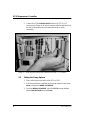
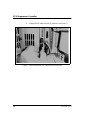
c. Locate the suppressor in the chromatography compartment.
d. Disconnect the SRS power source cable from the SRS cable (see
Figure 2). You may remove the cable from the system, or leave it
for future use.
Figure 2. Disconnecting the SRS Power Source Cable from the SRS Cable

Installing the SC20 in a DX-320 or DX-320J System
Doc. 031768-04 9/01 5
2. Locate the SUPPRESSOR cable extending from the front panel of
the SC20 Suppressor Controller (see Figure 3). Route this cable to the
chromatography compartment.
3. The SC20 SUPPRESSOR cable can be connected to an Atlas or SRS
suppressor:
_If you plan to operate with an Atlas suppressor, install it now.
(Refer to the Atlas suppressor manual for installation
instructions.) Connect the Atlas to the SC20 SUPPRESSOR
cable you routed to the chromatography compartment in Step 2.
_If you plan to operate with an existing SRS suppressor, connect
the SRS to the SC20 SUPPRESSOR cable you routed to the
chromatography compartment in Step 2.
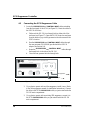
2.4 Connecting the Control Input Cable to the Pump
1. Locate the CONTROL INPUT cable extending from the SC20 front
panel (see Figure 3).
2. Open the upper door of the pump enclosure. Locate the TTL-2 OUT
connector in slot 4 of the electronics chassis.
Figure 3. SC20 Suppressor Controller Front Panel
VOLTS MILLIAMPS
CV
CC
SC20 SUPPRESSOR CONTROLLER
ADJUST
VOLTAGE CURRENT
To Pump
To Suppressor
POWER
ON
OFF
0.25A
0.5A
RANGE CC SET CONTROL INPUT
ON
SUPPRESSOR

SC20 Suppressor Controller
6Doc. 031768-04 9/01
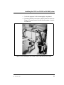
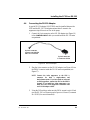
3. Connect the SC20 CONTROL INPUT cable to the TTL-2 OUT
connector (see Figure 4). Be sure to route the cable through the slot in
the side of the module; this will ensure that the door closes
completely.
2.5 Setting the Pump Options
1. Turn on the main power switch to the IC20 or IC25.
2. After the module has completed the power-up diagnostic tests, press
Menu to display the MENU of SCREENS.
3. From the MENU of SCREENS, select the SETUP screen and then
select PUMP OPTIONS and press Enter.
Figure 4. Connecting the Control Input Cable to the Pump TTL Connector

Installing the SC20 in a DX-320 or DX-320J System
Doc. 031768-04 9/01 7
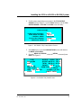
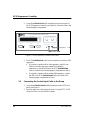
4. Use the cursor arrow buttons to navigate to the TTL2 OUTPUT
USAGE field (see Figure 5). Use the Select buttons to set the TTL2
OUTPUT USAGE to 0 FLOW. Press Enter to save the entry.
5. Press Menu twice to exit the PUMP OPTIONS screen and return to
the MENU of SCREENS.
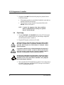
6. From the MENU of SCREENS, select the DETAIL screen and press
Enter (see Figure 6).
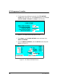
Figure 5. DX-320/DX-320J Pump Options Screen
Figure 6. DX-320/DX-320J Detail Screen
PUMP OPTIONS
PRESSURE UNITS:
PUMP HEAD MATERIAL:
PUMP HEAD VOLUME:
CONTROL MODE:
TTL2 OUTPUT USAGE:
25
PRESSURE
INERT
uL
0 FLOW
PSI
100
OUTPUT 0.05uS
LOCAL
OVEN TEMP
0 PSI
5.00 mL/MIN TTL1
TTL2
RLY1
RLY2
0
0
0
0
RANGE
P-POINT L= 0 R=0
LIMIT DIRECT CNTRL
OFFSET 189.13 uS
C READY
uS
SRS OFF mA
TEMP COMP 1.7
200 - 5000 PSI
TOTAL 189.18 uS
25
LOAD

SC20 Suppressor Controller
8Doc. 031768-04 9/01
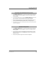
7. Navigate to the LIMIT field and set the pump low pressure limit to
1.38 MPa (200 psi):
_When pump operation is controlled by PeakNet®, select the low
pressure limit from the software.
_For front panel control, enter the low pressure limit on the
DETAIL screen (see Figure 6).
NOTE To protect the suppressor from alarm conditions,
Dionex recommends always entering a low pressure
limit of 1.38 MPa (200 psi).
2.6 Final Setup
1. Turn the VOLTAGE and CURRENT knobs on the SC20 front panel
(see Figure 3) fully counterclockwise to prevent high voltage and
current when the system is turned on.
2. Plug the SC20 power cord into an AC outlet.
3. This completes the SC20 installation procedure. Turn on the power to
all system components, including the SC20, and go on to Section 5
for SC20 operating instructions.
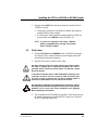
The third conductor in the power cable is the ground conductor. When
the cable is plugged into an appropriate receptacle, the SC20 is
grounded. Never operate the SC20 without an adequate cabinet
ground connection.
Le troisième conducteur dans le câble d'alimentation électrique est le
conducteur de mise à la masse. Lorsque le câble est branché dans
une prise correcte, le SC20 est mis à la masse. N'utilisez jamais le
SC20 sans un branchement correct à la masse de l'armoire.
Die dritte Ader im Netzkabel ist die Masseleitung. Sobald das Kabel in
die entsprechende Steckdose eingesteckt wird, ist das SC20 geerdet.
Betreiben Sie das SC20 unter keinen Umständen ohne geeignete
Masseverbindung des Gehäuses.

Installing the SC20 in a DX-500 or DX-600 System
Doc. 031768-04 9/01 9
3. Installing the SC20 in a DX-500 or DX-600 System
NOTE This procedure applies to the following pump modules:
the GP40, GP50, and GS50 Gradient Pumps and the
IP20, IP25, and IS25 Isocratic Pumps.
3.1 Initial Setup
1. Turn off the power to the chromatography system (including the
pump, detector, automated sampler, and chromatography
compartment).
2. Place the SC20 in the desired location; Dionex recommends installing
the SC20 near the chromatography compartment. Allow at least
15 cm (6 in) behind the SC20 for ventilation. Ambient temperature
should not exceed 40 °C (104 °F).
3.2 Connecting the SC20 Suppressor Cable
NOTE If the system already contains an Atlas suppressor,
disregard Step 1 and go on to Step 2.
1. If the system currently includes an SRS suppressor, you must
disconnect the SRS from the internal power supply. To disconnect the
SRS suppressor, do the following:
a. Open the door of the detector and locate the SRS cable connected
to J3 (SRS) of the SCR card in slot 2. (The label on the inside of
the door identifies the electronics cards.)


Installing the SC20 in a DX-500 or DX-600 System
Doc. 031768-04 9/01 11
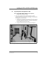
c. Locate the suppressor in the chromatography compartment.
d. Disconnect the SRS power source cable from the SRS cable (see
Figure 8). You may remove the cable from the system, or leave it
for future use.
Figure 8. Disconnecting the SRS Power Source Cable from the SRS Cable

SC20 Suppressor Controller
12 Doc. 031768-04 9/01
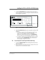
2. Locate the SUPPRESSOR cable extending from the front panel of
the SC20 Suppressor Controller (see Figure 9). Route this cable to the
chromatography compartment.
3. The SC20 SUPPRESSOR cable can be connected to an Atlas or SRS
suppressor:
_If you plan to operate with an Atlas suppressor, install it now.
(Refer to the Atlas suppressor manual for installation
instructions.) Connect the Atlas to the SC20 SUPPRESSOR
cable you routed to the chromatography compartment in Step 2.
_If you plan to operate with an existing SRS suppressor, connect
the SRS to the SC20 SUPPRESSOR cable you routed to the
chromatography compartment in Step 2.
3.3 Connecting the Control Input Cable to the Pump
1. Locate the CONTROL INPUT cable extending from the SC20 front
panel (see Figure 9).
2. Open the upper door of the pump enclosure. Locate the TTL-2 OUT
connector in slot 4 of the electronics chassis.
Figure 9. SC20 Suppressor Controller Front Panel
VOLTS MILLIAMPS
CV
CC
SC20 SUPPRESSOR CONTROLLER
ADJUST
VOLTAGE CURRENT
To Pump
To Suppressor
POWER
ON
OFF
0.25A
0.5A
RANGE CC SET CONTROL INPUT
ON
SUPPRESSOR

Installing the SC20 in a DX-500 or DX-600 System
Doc. 031768-04 9/01 13
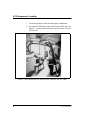
3. Connect the SC20 CONTROL INPUT cable to the TTL-2 OUT
connector (see Figure 10). Be sure to route the cable through the slot
in the side of the module; this will ensure that the door closes
completely.
3.4 Setting the Pump Options
1. Turn on the main power switch to the pump.
2. After the pump has completed the power-up diagnostic tests, press
Menu to display the MENU of SCREENS.
3. From the MENU of SCREENS, select PUMP OPTIONS and press
Enter.
Figure 10. Connecting the Control Input Cable to the Pump TTL Connector

SC20 Suppressor Controller
14 Doc. 031768-04 9/01
4. Use the cursor arrow buttons to navigate to the TTL2 OUTPUT
USAGE field (see Figure 11). Use the Select buttons to set the TTL2
OUTPUT USAGE to 0 FLOW. Press Enter to save the entry.
5. Press Menu to exit the PUMP OPTIONS screen and return to the
MENU of SCREENS.
6. From the MENU of SCREENS, select the DETAIL screen and press
Enter (see Figure 12).
Figure 11. DX-500/DX-600 Pump Options Screen
Figure 12. DX-500/DX-600 Detail Screen
PUMP OPTIONS
PRESSURE UNITS:
PUMP HEAD MATERIAL:
PUMP HEAD VOLUME:
CONTROL MODE:
TTL2 OUTPUT USAGE:
25
PRESSURE
INERT
uL
0 FLOW
PSI
0.30
59
LOCKED RMT
COLUMN
DETAIL SCREEN
100.0 %A TTL1
TTL2
RLY1
RLY2
0
0
0
0
LOAD
200-5000 PSI
0.0 %B
0.0 %C
0.0 %D LIMIT
DIRECT CNTRL
PSI
mL/MIN
SAMPLE
A

Installing the SC20 in a DX-500 or DX-600 System
Doc. 031768-04 9/01 15
7. Navigate to the LIMIT field and set the pump low pressure limit to
1.38 MPa (200 psi).
_When pump operation is controlled by PeakNet, select the low
pressure limit from the software.
_For front panel control and when creating methods, set the low
pressure limit on the DETAIL screen (see Figure 12).
NOTE To protect the suppressor from alarm conditions,
Dionex recommends always entering a low pressure
limit of 1.38 MPa (200 psi).
3.5 Final Setup
1. Turn the VOLTAGE and CURRENT knobs on the SC20 front panel
(see Figure 9) fully counterclockwise to prevent high voltage and
current when the system is turned on.
2. Plug the SC20 power cord into an AC outlet.
3. This completes the SC20 installation procedure. Turn on the power to
all system components, including the SC20, and go on to Section 5
for SC20 operating instructions.
The third conductor in the power cable is the ground conductor. When
the cable is plugged into an appropriate receptacle, the SC20 is
grounded. Never operate the SC20 without an adequate cabinet
ground connection.
Le troisième conducteur dans le câble d'alimentation électrique est le
conducteur de mise à la masse. Lorsque le câble est branché dans
une prise correcte, le SC20 est mis à la masse. N'utilisez jamais le
SC20 sans un branchement correct à la masse de l'armoire.
Die dritte Ader im Netzkabel ist die Masseleitung. Sobald das Kabel in
die entsprechende Steckdose eingesteckt wird, ist das SC20 geerdet.
Betreiben Sie das SC20 unter keinen Umständen ohne geeignete
Masseverbindung des Gehäuses.

SC20 Suppressor Controller
16 Doc. 031768-04 9/01
4. Installing the SC20 in a DX-120
4.1 Initial Setup
1. Turn off the power to the DX-120.
2. Place the SC20 in the desired location; Dionex recommends installing
the SC20 near the DX-120. Allow at least 15 cm (6 in) behind the
SC20 for ventilation. Ambient temperature should not exceed 40 °C
(104 °F).
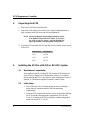
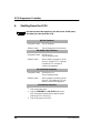
4.2 Disconnecting the SRS A Power Source Cable
NOTE Complete this section only if an SRS suppressor is
already installed. Otherwise, go on to Section 4.3.
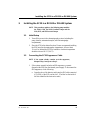
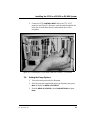
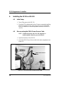
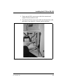
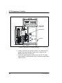
1. Open the front door of the DX-120.
2. Locate the SRS A Power Source cable in the main compartment (see
Figure 13).
Figure 13. The DX-120 SRS A Power Source Cable
SRS A Power Source
Cable
La page est en cours de chargement...
La page est en cours de chargement...
La page est en cours de chargement...
La page est en cours de chargement...
La page est en cours de chargement...
La page est en cours de chargement...
La page est en cours de chargement...
La page est en cours de chargement...
La page est en cours de chargement...
La page est en cours de chargement...
La page est en cours de chargement...
La page est en cours de chargement...
-
 1
1
-
 2
2
-
 3
3
-
 4
4
-
 5
5
-
 6
6
-
 7
7
-
 8
8
-
 9
9
-
 10
10
-
 11
11
-
 12
12
-
 13
13
-
 14
14
-
 15
15
-
 16
16
-
 17
17
-
 18
18
-
 19
19
-
 20
20
-
 21
21
-
 22
22
-
 23
23
-
 24
24
-
 25
25
-
 26
26
-
 27
27
-
 28
28
-
 29
29
-
 30
30
-
 31
31
-
 32
32


Thermo Fisher Scientific SC20 Suppressor Controller Mode d'emploi
- Taper
- Mode d'emploi
dans d''autres langues
Documents connexes


Autres documents
-
Eden MA40 Le manuel du propriétaire
-
Epson TM-P20 Series Manuel utilisateur
-
Windsor Saber Compact 20 Le manuel du propriétaire
-
Proctor-Silex 33111Y Le manuel du propriétaire
-
Sony CDP-CX88ES Mode d'emploi
-
-
-
Mettler Toledo APS768x Series Guide d'installation
-
Enclave Audio EA-100-HTIB-US Le manuel du propriétaire