Skil MAG77LT Manuel utilisateur
- Catégorie
- Outils électroportatifs
- Taper
- Manuel utilisateur
Ce manuel convient également à

IMPORTANT: IMPORTANT : IMPORTANTE:
Read Before Using Lire avant usage Leer antes de usar
For English Version Version française Versión en español
See page 2 Voir page 17 Ver la página 32
Operating/Safety Instructions
Consignes d’utilisation/de sécurité
Instrucciones de funcionamiento y seguridad
1-877-SKIL999 (1-877-754-5999) www.skil.com
Call Toll Free for
Consumer Information
& Service Locations
Pour obtenir des informations
et les adresses de nos centres
de service après-vente,
appelez ce numéro gratuit
Llame gratis para
obtener información
para el consumidor y
ubicaciones de servicio
MAG77LT
SM 1619X04759 11-12_SM 1619X04759 11-12.qxp 11/20/12 2:05 PM Page 1

-2-
$692(9,(:(-,;@
,,7>692(9,(*3,(5(5+>,3330;Cluttered
or dark areas invite accidents.
6 56; 67,9(;, 76>,9 ;663: 05 ,?736:0=,
(;46:7/,9,::<*/ (: 05 ;/, 79,:,5*, 6-
-3(44()3, 308<0+: .(:,: 69 +<:;Power
tools create sparks which may ignite the dust
or fumes.
,,7 */03+9,5 (5+)@:;(5+,9: (>(@ >/03,
67,9(;05. ( 76>,9 ;663 Distractions can
cause you to lose control.
3,*;90*(3:(-,;@
6>,9 ;663 73<.: 4<:; 4(;*/ ;/, 6<;3,;
,=,946+0-@;/,73<.05(5@>(@656;
<:, (5@ (+(7;,9 73<.: >0;/ ,(9;/,+
.96<5+,+ 76>,9 ;663: Unmodified plugs
and matching outlets will reduce risk of electric
shock.
=60+)6+@*65;(*;>0;/,(9;/,+69.96<5+,+
:<9-(*,::<*/ (: 707,: 9(+0(;69:9(5.,:
(5+9,-90.,9(;69:There is an increased risk
of electric shock if your body is earthed or
grounded.
656; ,?76:, 76>,9 ;663: ;6 9(05 69 >,;
*65+0;065: Water entering a power tool will
increase the risk of electric shock.
656;()<:,;/,*69+,=,9<:,;/,*69+
-69*(99@05.7<3305.69<573<..05.;/,76>,9
;663,,7*69+(>(@-964/,(;603:/(97
,+.,:6946=05.7(9;:Damaged or entangled
cords increase the risk of electric shock.
$/,5 67,9(;05. ( 76>,9 ;663 6<;+669:
<:,(5,?;,5:065*69+:<0;()3,-696<;+669
<:, Use of a cord suitable for outdoor use
reduces the risk of electric shock.
-67,9(;05.(76>,9;66305(+(4736*(;065
0:<5(=60+()3,<:,(96<5+(<3;09*<0;
5;,99<7;,9796;,*;,+:<773@Use of
an GFCI reduces the risk of electric shock.
,9:65(3:(-,;@
;(@(3,9; >(;*/>/(;@6<(9, +605. (5+
<:, *64465 :,5:, >/,5 67,9(;05. (
76>,9;663656;<:,(76>,9;663>/03,
@6<(9,;09,+69<5+,9;/,05-3<,5*,6-+9<.:
(3*6/63694,+0*(;065A moment of inattention
while operating power tools may result in
serious personal injury.
":,7,9:65(3796;,*;0=,,8<074,5;3>(@:
>,(9 ,@, 796;,*;065 Protective equipment
such as dust mask, non-skid safety shoes, hard
hat, or hearing protection used for appropriate
conditions will reduce personal injuries.
9,=,5;<505;,5;065(3:;(9;05.5:<9,;/,
:>0;*/ 0: 05 ;/, 6--76:0;065 ),-69,
*655,*;05.;676>,9:6<9*,(5+69)(;;,9@
7(*2 70*205. <7 69 *(99@05. ;/, ;663
Carrying power tools with your finger on the
switch or energizing power tools that have the
switch on invites accidents.
,46=,(5@(+1<:;05.2,@69>9,5*/),-69,
;<9505. ;/, 76>,9 ;663 65 A wrench or a
key left attached to a rotating part of the
power tool may result in personal injury.
656;6=,99,(*/,,77967,9-66;05.(5+
)(3(5*, (; (33 ;04,: This enables better
control of the power tool in unexpected
situations.
9,::7967,93@656;>,(9366:,*36;/05.
69 1,>,39@ ,,7 @6<9 /(09 *36;/05. (5+
.36=,: (>(@ -964 46=05. 7(9;: Loose
clothes, jewelry or long hair can be caught in
moving parts.
-+,=0*,:(9,796=0+,+-69;/,*655,*;065
6-+<:;,?;9(*;065(5+*633,*;065-(*030;0,:
,5:<9,;/,:, (9, *655,*;,+(5+7967,93@
<:,+Use of dust collection can reduce dust-
related hazards.
6>,9;663<:,(5+*(9,
6 56; -69*, ;/, 76>,9 ;663 ":, ;/,
*699,*;76>,9 ;663-69@6<9(7730*(;065The
correct power tool will do the job better and
safer at the rate for which it was designed.
656;<:,;/,76>,9;6630-;/,:>0;*/+6,:
56; ;<95 0; 65 (5+ 6-- Any power tool that
cannot be controlled with the switch is
dangerous and must be repaired.
,(+(33:(-,;@>(9505.:(5+(3305:;9<*;065:Failure to follow the warnings
and instructions may result in electric shock, fire and/or serious injury.
#$ !"! "!"
The term “power tool” in the warnings refers to your mains-operated (corded) power tool or
battery-operated (cordless) power tool.
!
WARNING
,5,9(36>,9!663 (-,;@$(9505.:
SM 1619X04759 11-12_SM 1619X04759 11-12.qxp 11/20/12 2:05 PM Page 2

-3-
0:*655,*;;/,73<.-964;/,76>,9:6<9*,
(5+69;/,)(;;,9@7(*2-964;/,76>,9;663
),-69, 4(205.(5@(+1<:;4,5;:*/(5.05.
(**,::690,: 69 :;6905. 76>,9;663: Such
preventive safety measures reduce the risk of
starting the power tool accidentally.
;69,0+3,76>,9;663: 6<;6-;/,9,(*/6-
*/03+9,5(5++656;(336>7,9:65:<5-(4030(9
>0;/;/,76>,9;66369;/,:,05:;9<*;065:;6
67,9(;, ;/, 76>,9 ;663 Power tools are
dangerous in the hands of untrained users.
(05;(0576>,9;663:/,*2-6940:(30.54,5;
69 )05+05. 6- 46=05. 7(9;: )9,(2(., 6-
7(9;: (5+ (5@ 6;/,9 *65+0;065 ;/(; 4(@
(--,*;;/,76>,9;663E:67,9(;065-+(4(.,+
/(=, ;/, 76>,9 ;663 9,7(09,+ ),-69, <:,
Many accidents are caused by poorly
maintained power tools.
,,7*<;;05.;663::/(97(5+*3,(5Properly
maintained cutting tools with sharp cutting
edges are less likely to bind and are easier to
control.
":, ;/, 76>,9 ;663 (**,::690,: (5+ ;663
)0;:,;*05(**69+(5*,>0;/;/,:,05:;9<*;065:
;(205.05;6(**6<5;;/,>69205.*65+0;065:
(5+ ;/, >692 ;6 ), 7,9-694,+ Use of the
power tool for operations different from those
intended could result in a hazardous situation.
,9=0*,
(=,@6<976>,9;663:,9=0*,+)@(8<(30-0,+
9,7(09 7,9:65 <:05. 653@ 0+,5;0*(3
9,73(*,4,5;7(9;: This will ensure that the
safety of the power tool is maintained.
(-,;@<3,:-6909*<3(9 (>:
,(+(33:(-,;@>(9505.:(5+(3305:;9<*;065:
!
WARNING
<;;05.796*,+<9,:
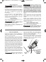
,,7 /(5+: (>(@ -964
*<;;05. (9,( (5+ ;/, )3(+,
,,7@6<9:,*65+/(5+65(<?030(9@/(5+3,
6946;69/6<:05. If both hands are holding
the saw, they cannot be cut by the blade.
6 56; 9,(*/ <5+,95,(;/ ;/, >69270,*,
The guard cannot protect you from the blade
below the workpiece.
+1<:;;/,*<;;05.+,7;/;6;/,;/0*25,::6-
;/,>69270,*,Less than a full tooth of the
blade teeth should be visible below the
workpiece.
,=,9/63+70,*,),05. *<;05 @6<9 /(5+:
69(*96::@6<93,. ,*<9,;/,>69270,*,;6
(:;()3,73(;-694 It is important to support
the work properly to minimize body exposure,
blade binding, or loss of control.
63+;/,76>,9;663)@05:<3(;,+.907705.
:<9-(*,: 653@ >/,5 7,9-69405. (5
67,9(;065 >/,9, ;/, *<;;05. ;663 4(@
*65;(*; /0++,5 >0905. 690;:6>5*69+
Contact with a "live" wire will also make
exposed metal parts of the tool “live” and could
give the operator an electric shock.
$/,5 907705. (3>(@: <:, ( 907 -,5*, 69
:;9(0./; ,+., .<0+, This improves the
accuracy of cut and reduces the chance of
blade binding.
3>(@: <:, )3(+,: >0;/ *699,*; :0A, (5+
:/(7, +0(465+ =,9:<: 96<5+ 6- (9)69
/63,:Blades that do not match the mounting
hardware of the saw will run eccentrically,
causing loss of control.
,=,9 <:, +(4(.,+ 69 05*699,*; )3(+,
>(:/,9:69)63; The blade washers and bolt
were specially designed for your saw, for
optimum performance and safety of operation.
5:7,*; ;/, *65+0;065 (5+ 8<(30;@ 6- ;/,
>66+ (5+ 9,46=, (33 5(03: -964 3<4),9
),-69,*<;;05.Wet lumber, green lumber or
pressure treated lumber require special
attention during cutting operation to prevent
kickback.
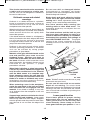
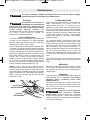
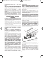
63+;/, :(> -0943@ ;6 79,=,5; 36:: 6-
*65;963 Figures in this manual illustrate
typical hand support of the saw.
,7,5+05.<765 <:, ;/, :>0;*/4(@56;
3(:;;/,30-,6-;/,:(>-;/,:>0;*/:/6<3+
-(0305;/,CD76:0;065;/,:(>4(@56;
:;(9; - 0; :/6<3+ -(03 >/03, ;/,:(> 0:
9<5505.;/,:(>4(@56;:/<;6-- If either
occurs, unplug the saw immediately and do
not use until repaired.
DANGER
!
SM 1619X04759 11-12_SM 1619X04759 11-12.qxp 11/20/12 2:05 PM Page 3

-4-
!/0:*09*<3(9:(>:/6<3+56;),46<5;,+;6
(;()3, (5+ *65=,9;,+ ;6 ( ;()3, :(>
Circular saws are not designed or intended to
be used as table saws.
0*2)(*2*(<:,:(5+9,3(;,+
>(9505.:
Kickback is a sudden reaction to a pinched,
bound or misaligned saw blade, causing an
uncontrolled saw to lift up and out of the
workpiece toward the operator.
When the blade is pinched or bound tightly by
the kerf closing down, the blade stalls and the
motor reaction drives the unit rapidly back
toward the operator.
If the blade becomes twisted or misaligned in
the cut, the teeth at the back edge of the blade
can dig into the top surface of the wood
causing the blade to climb out of the kerf and
jump back toward the operator.
Kickback is the result of tool misuse and/or
incorrect operating procedures or conditions
and can be avoided by taking proper
precautions as given below:
(05;(05(-094.907>0;/)6;//(5+:65;/,
:(> (5+ 76:0;065 @6<9 (94: ;6 9,:0:;
20*2)(*2 -69*,: 6:0;065 @6<9 )6+@ ;6
,0;/,9:0+,6-;/,)3(+,)<;56;05305,>0;/
;/,)3(+, Kickback could cause the saw to
jump backwards, but kickback forces can be
controlled by the operator, if proper
precautions are taken.
$/,5)3(+,0:)05+05.69>/,505;,99<7;05.
(*<;-69(5@9,(:659,3,(:,;/,;90..,9(5+
/63+ ;/, :(> 46;0653,:: 05 ;/, 4(;,90(3
<5;03;/,)3(+,*64,:;6(*6473,;, :;67
,=,9(;;,47;;69,46=,;/,:(>-964;/,
>692 69 7<33 ;/,:(> )(*2>(9+ >/03, ;/,
)3(+,0:0546;0656920*2)(*24(@6**<9
Investigate and take corrective action to
eliminate the cause of blade binding.
$/,5 9,:;(9;05. ( :(> 05 ;/, >69270,*,
*,5;,9;/,:(>)3(+,05;/,2,9-(5+*/,*2
;/(; :(> ;,,;/ (9, 56; ,5.(.,+ 05;6 ;/,
4(;,90(3 If saw blade is binding, it may walk
up or kickback from the workpiece as the saw
is restarted.
<7769;3(9.,7(5,3:;6405040A,;/,90:26-
)3(+, 705*/05.(5+20*2)(*2 Large panels
tend to sag under their own weight. Supports
must be placed under the panel on both sides,
near the line of cut and near the edge of the
panel.
6 56; <:, +<33 69 +(4(.,+ )3(+,:
Unsharpened or improperly set blades
produce narrow kerf causing excessive friction,
blade binding and kickback.
3(+, +,7;/ (5+ ),=,3 (+1<:;05. 36*205.
3,=,9: 4<:; ), ;0./; (5+ :,*<9, ),-69,
4(205.*<; If blade adjustment shifts while
cutting, it may cause binding and kickback.
":, ,?;9( *(<;065 >/,5 :(>05. 05;6
,?0:;05. >(33: 69 6;/,9 )305+ (9,(: The
protruding blade may cut objects that can
cause kickback.
!/, )3(+, >(:/,9: (5+ ;/, )63; 65 @6<9
:(>/(=, ),,5 +,:0.5,+ ;6 >692 (: (
*3<;*/;69,+<*,;/,05;,5:0;@6-(20*2)(*2
"5+,9:;(5+;/,67,9(;065 (5+ :,;;05.:6-
;/, #!" "! The proper
setting of the clutch, combined with firm
handling of the saw will allow you to control
kickback.
,=,9 73(*, @6<9 /(5+ ),/05+ ;/, :(>
)3(+,Kickback could cause the saw to jump
backwards over your hand.
6 56; <:, ;/, :(> >0;/ (5 ,?*,::0=,
+,7;/ 6- *<; :,;;05. Too much blade
exposure increases the likelihood of the blade
twisting in the kerf and increases the surface
area of the blade available for pinching that
leads to kickback.
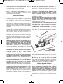
6>,9.<(9+-<5*;065
/,*2 36>,9 .<(9+ -69 7967,9 *36:05.
),-69, ,(*/ <:, 6 56; 67,9(;, :(> 0-
36>,9 .<(9+ +6,: 56; 46=, -9,,3@(5+
*36:, 05:;(5;3@ ,=,9 *3(47 69 ;0, ;/,
36>,9.<(9+05;6;/,67,576:0;065 If saw is
VARI-TORQUE
CLUTCH
SM 1619X04759 11-12_SM 1619X04759 11-12.qxp 11/20/12 2:05 PM Page 4

-5-
GFCI and personal protection devices like
electrician’s rubber gloves and footwear will
further enhance your personal safety.
6 56; <:,653@9(;,+;663:>0;/(
76>,9:<773@ While the tool may appear to
work, the electrical components of the AC
rated tool are likely to fail and create a hazard
to the operator.
,,7/(5+3,: +9@ *3,(5(5+ -9,,-964603
(5+ .9,(:, Slippery hands cannot safely
control the power tool.
":,*3(47:696;/,979(*;0*(3>(@;6:,*<9,
(5+ :<7769; ;/, >69270,*, ;6 ( :;()3,
73(;-694Holding the work by hand or against
your body is unstable and may lead to loss of
control.
,=,367( 7,906+0*4(05;,5(5*,:*/,+<3,
-69 @6<9;663$/,5 *3,(505.( ;663),
*(9,-<356;;6+0:(::,4)3, (5@769;0656-
;/, ;663 :05*, 05;,95(3 >09,: 4(@ ),
40:73(*,+69705*/,+69:(-,;@.<(9+9,;<95
:7905.: 4(@ ), 047967,93@ 46<5;,+
Certain cleaning agents such as gasoline,
carbon tetrachloride, ammonia, etc. may
damage plastic parts.
Risk of injury to user. The power cord must only
be serviced by a Skil Factory Service Center or
Autho rized Skil Service Station.
64,+<:;*9,(;,+)@76>,9
:(5+05.:(>05..905+05.
+903305. (5+ 6;/,9 *65:;9<*;065 (*;0=0;0,:
*65;(05:*/,40*(3:256>5;6*(<:,*(5*,9
)09;/ +,-,*;: 69 6;/,9 9,796+<*;0=, /(94
64,,?(473,:6-;/,:,*/,40*(3:(9,
• Lead from lead-based paints,
• Crystalline silica from bricks and cement and
other masonry products, and
• Arsenic and chromium from chemically-
treated lumber.
Your risk from these exposures varies,
depending on how often you do this type of
work. To reduce your exposure to these
chemicals: work in a well ventilated area, and
work with approved safety equipment, such as
those dust masks that are specially designed
to filter out microscopic particles.
++0;065(3 (-,;@$(9505.:
!
WARNING
accidentally dropped, lower guard may be
bent. Raise the lower guard only with the lower
guard lift lever and make sure it moves freely
and does not touch the blade or any other part,
in all angles and depths of cut.
/,*2 ;/, 67,9(;065 6- ;/, 36>,9 .<(9+
:7905.-;/,.<(9+(5+;/,:7905.(9,56;
67,9(;05.7967,93@;/,@4<:;),:,9=0*,+
),-69, <:, Lower guard may operate
sluggishly due to damaged parts, gummy
deposits, or a buildup of debris.
6>,9.<(9+:/6<3+),9,;9(*;,+4(5<(33@
653@ -69 :7,*0(3 *<;: :<*/ (: C3<5.,
<;:D(5+ C6476<5+<;:DRaise lower
guard by Lower Guard Lift lever and as soon
as blade enters the material, the lower guard
must be released. For all other sawing, the
lower guard should operate automatically.
3>(@: 6):,9=, ;/(; ;/, 36>,9 .<(9+ 0:
*6=,905. ;/, )3(+, ),-69, 73(*05. :(>
+6>5 65 ),5*/ 69 -3669 An unprotected,
coasting blade will cause the saw to walk
backwards, cutting whatever is in its path. Be
aware of the time it takes for the blade to stop
after switch is released.
656;9<5;/,;663>/03,*(99@05.0;(;@6<9
:0+, 6>,9 .<(9+ 4(@ ), 67,5,+ )@ (
*65;(*; >0;/@6<9 *36;/05. Accidental
contact with the spinning saw blade could
result in serious personal injury.
,906+0*(33@ 9,46=, ;/, )3(+, *3,(5 ;/,
<77,936>,9.<(9+:(5+;/,/<)(9,(>0;/
2,96:,5,(5+>07,0;+9@69)36>0;*3,(5
>0;/*6479,::,+(09Preventive maintenance
and properly operating guard will reduce the
probability of an accident.
SM 1619X04759 11-12_SM 1619X04759 11-12.qxp 11/20/12 2:05 PM Page 5

-6-
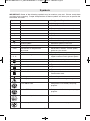
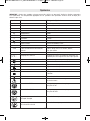
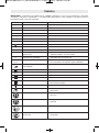
!! Some of the following symbols may be used on your tool. Please study them
and learn their meaning. Proper interpretation of these symbols will allow you to operate the
tool better and safer.
@4)63 (4, ,:0.5(;065?73(5(;065
V Volts Voltage (potential)
A Amperes Current
Hz Hertz Frequency (cycles per second)
W Watt Power
kg Kilograms Weight
min Minutes Time
s Seconds Time
Diameter Size of drill bits, grinding wheels, etc.
n
0
No load speed Rotational speed, at no load
n Rated speed Maximum attainable speed
.../min Revolutions or reciprocation Revolutions, strokes, surface speed,
per minute orbits etc. per minute
0 Off position Zero speed, zero torque...
1, 2, 3, ... Selector settings Speed, torque or position settings.
I, II, III, Higher number means greater speed
Infinitely variable selector with off Speed is increasing from 0 setting
Arrow Action in the direction of arrow
Alternating current Type or a characteristic of current
Direct current Type or a characteristic of current
Alternating or direct current Type or a characteristic of current
Class II construction Designates Double Insulated
Construction tools.
Earthing terminal Grounding terminal
Warning symbol Alerts user to warning messages
Li-ion RBRC seal Designates Li-ion battery recycling
program
Ni-Cad RBRC seal Designates Ni-Cad battery recycling
program
Read manual symbol Alerts user to read manual
Wear eye protection symbol Alerts user to wear eye protection
@4)63:
0
SM 1619X04759 11-12_SM 1619X04759 11-12.qxp 11/20/12 2:05 PM Page 6

-7-
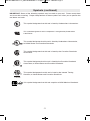
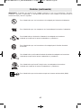
This symbol designates that this tool is listed by Underwriters Laboratories.
This symbol designates that this tool is listed by the Canadian Standards
Association.
This symbol designates that this tool is listed by the Canadian Standards
Association, to United States and Canadian Standards.
This symbol designates that this tool complies to NOM Mexican Standards.
This symbol designates that this tool is listed by the Intertek Testing
Services, to United States and Canadian Standards.
@4)63:*65;05<,+
!! Some of the following symbols may be used on your tool. Please study them
and learn their meaning. Proper interpretation of these symbols will allow you to operate the
tool better and safer.
This symbol designates that this component is recognized by Underwriters
Laboratories.
This symbol designates that this tool is listed by Underwriters Laboratories,
to United States and Canadian Standards.
SM 1619X04759 11-12_SM 1619X04759 11-12.qxp 11/20/12 2:05 PM Page 7

-8-
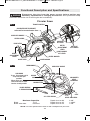
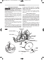
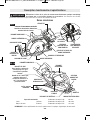
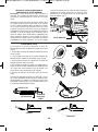
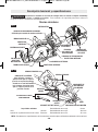
<5*;065(3,:*907;065(5+ 7,*0-0*(;065:
0:*655,*; ;/, 73<. -964 ;/, 76>,9 :6<9*, ),-69, 4(205. (5@
(::,4)3@(+1<:;4,5;:69*/(5.05.(**,::690,:. Such preventive safety
measures reduce the risk of starting the tool accidentally.
!
WARNING
09*<3(9 (>:
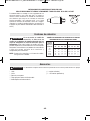
! For tool specifications refer to the nameplate on your tool.
(?04<4(7(*0;0,:
Blade 7-1/4"
Blade arbor hole Diamond
Depth of cut at 90° 2-3/8"
Depth of cut at 45° 1-29/32"
Depth of cut at 53° 1-5/8"
1/4
1/2
3/4
1X
OOD
MBER
TRIGGER SWITCH
AUXILIARY HANDLE
MAIN HANDLE
DEPTH
ADJUSTMENT
LEVER
FOOT
LOWER GUARD
LOWER GUARD
LIFT LEVER
CALIBRATED DEPTH BRACKET
Calibrated For Standard Lumber Sizes
BLADE WRENCH
& STORAGE AREA
SAW HOOK
To use, lift up hook until it
snaps into the open
position.
When not in use, always
lower hook until it snaps
into the closed position.
CALIBRATED
BEVEL
QUADRANT
UPPER GUARD
45° STOP SPRING
BEVEL
ADJUSTMENT
LEVER
BLADE STUD
OUTER WASHER
LOCK BUTTON
FIG. 1
FIG. 1A
DEPTH OF
CUT MARKS
CONTOUR
OF LEVER
OIL PLUG
PIVOT STUD
AUXILIARY HANDLE
BRUSH
CAP
BEVEL INDICATOR
SM 1619X04759 11-12_SM 1619X04759 11-12.qxp 11/20/12 2:05 PM Page 8

-9-
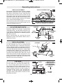
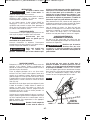
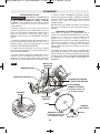
::,4)3@
!!!
0:*655,*; ;/, 73<. -964
;/, 76>,9 :6<9*, ),-69,
4(205. (5@ (::,4)3@ (+1<:;4,5;: 69
*/(5.05. (**,::690,:. Such preventive
safety measures reduce the risk of starting
the tool accidentally.
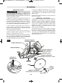
1. Press the lock button and turn wrench until
lock button en gages. Saw shaft is now locked.
Continue to depress button, turn wrench
clockwise and remove BLADE STUD and
OUTER WASHER (Fig. 2).
2. Retract the lower guard all the way up into
the upper guard. While retracting the lower
guard, check operation and condition of the
LOWER GUARD SPRING.
3. Make sure the saw teeth and arrow on the
blade point in the same direction as the arrow
on the lower guard.
4. Slide blade through slot in the foot and
mount it against the INNER WASHER on the
shaft. Be sure the large diameter of the INNER
and OUTER washers lay flush against the blade.
5. Reinstall OUTER WASHER. First tighten
BLADE STUD finger tight, then TIGHTEN
BLADE STUD 1/8 TURN (45˚) WITH THE
WRENCH PROVIDED.
Do not use wrenches with longer handles,
since it may lead to over tightening of the
blade stud.
#!""!
This clutching action is provided by the friction
of the OUTER WASHER against the BLADE
and permits the blade shaft to turn when the
blade encounters excessive resistance. When
the BLADE STUD is properly tightened (as
described in No. 5 of Attaching The Blade), the
blade will slip when it encounters ex cessive
resistance, thus reducing saw’s tendency to
KICKBACK.
One setting may not be sufficient for cutting all
materials. If ex cessive blade slippage occurs,
tighten the blade stud a fraction of a turn more
(less than 1/8 turn). OVERTIGHTENING THE
BLADE STUD NULLIFIES THE EFFECTIVE-
NESS OF THE CLUTCH.
!
WARNING
1/4
1/2
3/4
1X
OOD
MBER
LOWER GUARD
SPRING
Loosen
Tighten
UPPER GUARD
LOWER
GUARD
OUTER WASHER Large Diameter
Faces Blade
INNER WASHER
Large Diameter Faces Blade
SAW SHAFT
AUXILIARY HANDLE
LOWER GUARD
LIFT LEVER
BLADE
STUD
BLADE
FIG. 2
LOCK
BUTTON
SM 1619X04759 11-12_SM 1619X04759 11-12.qxp 11/20/12 2:05 PM Page 9

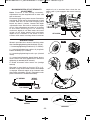
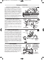
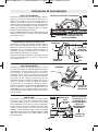
!" !!
Disconnect plug from power source. Loosen
the depth adjustment lever located between
the guard and handle of saw. Hold the foot
down with one hand and raise or lower saw by
the handle. Align the bottom contour of depth
adjustment lever with the desired depth of cut
mark on calibrated depth bracket and tighten
lever. Check desired depth (Fig. 1).
Not more than one tooth length of the blade
should extend below the material to be cut, for
minimum splintering (Fig. 3).
B"!!
Disconnect plug from power source. Set foot to
maximum depth of cut setting. Loosen bevel
adjustment lever, set the bevel indicator to 0°
on quadrant, retighten lever and check for 90°
angle between the blade and bottom plane of
foot with a square.
Make adjustments by turning the small
alignment screw from bottom side of foot, if
necessary (Fig. 4).
#" !!
Disconnect plug from power source. The foot
can be adjusted up to 45° by loosening the
bevel adjustment lever at the front of the saw.
Align to desired angle on calibrated quadrant
and then tighten bevel adjustment lever (Fig. 5).
For bevel adjustments above 45° loosen bevel
adjustment lever, depress 45° stop spring (Fig.
6), align foot to desired angle mark over 45 ° on
quadrant and tighten lever. Because of the
increased amount of blade engagement in the
work and decreased stability of the foot, blade
binding may occur. Keep the saw steady and
the foot firmly on the workpiece.
7,9(;05.5:;9<*;065:
"
For a 0° cut, use the large notch in the foot.
For 45° bevel cuts, use the small notch (Fig.
6). The cutting guide notch will give an
approximate line of cut. Make sample cuts in
scrap lumber to verify actual line of cut. This
will be helpful because of the number of
different blade types and thicknesses
available. To ensure minimum splintering on
the good side of the material to be cut, face
the good side down.
53
25
20
15
10
BLADE
90°
FOOT
BEVEL
ADJUSTMENT
LEVER
QUADRANT
FIG. 4
BEVEL
INDICATOR
QUADRANT
BEVEL
ADJUSTMENT
LEVER
FIG. 5
FIG. 6
FOOT
45° BEVEL
CUTS
0° CUTS
PUSH 45° STOP
SPRING IN DIRECTION
OF ARROW FOR
BEVEL ADJUSTMENTS
ABOVE 45
B
45° STOP
SPRING
ALIGNMENT
SCREW
-10-
DEPTH ADJUSTMENT LEVER
ONE TOOTH LENGTH SHOULD PENETRATE
WOOD FOR MINIMUM SPLINTERING
FIG. 3
SM 1619X04759 11-12_SM 1619X04759 11-12.qxp 11/20/12 2:05 PM Page 10

-11-
%"!"! !!&
" !!
6;,; Feature is set during assembly.
Adjustment may be required due to wear and
tear on the tool.
Disconnect plug from power source. Set tool to
zero bevel. Place tool on foot plate onto a level
surface with rear of foot over hanging work
bench by about 2 inches. Loosen the depth
adjustment lever. Set tool to maximum depth
of cut. If the adjustment set screw is in contact
to the motor housing prior to achieving
maximum depth of cut then lower set screw
using a 3/16” Allen wrench until maximum
depth of cut is reached. If set screw is not in
contact with motor housing when maximum
depth of cut is reached then raise the set
screw until it just engages the motor housing
(Fig 7).
FIG. 7
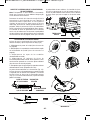
$"
Wrench provided has several functions other
than loosening/tightening the blade bolt (Fig. 8).
1. Loosening/tightening blade bolt (1/2” wrench)
2. Loosening/tightening combo oil plug/lock
button assembly (1/2” wrench)
3. Loosening/tightening brush caps (slotted
driver)
4. Loosening/tightening bevel/depth levers
when levers are over tightened or additional
tightening is needed (9/16” wrench)
5. Blade diamond arbor knock out (wedge
feature)
Storage is provided on the tool (Fig. 1A).
Wrench is fully seated when second lock detent
is engage. Wrench needs to be inserted with
the correct orientation (Fig. 9). Damage to work
piece could occur if inserted incorrectly.
SET SCREW
1
2
3
4
5
1/2" WRENCH
9/16" WRENCH
WEDGE
FEATURE
SLOTTED
DRIVER
CORRECT
INCORRECT
FIG. 9
FIG. 8
SM 1619X04759 11-12_SM 1619X04759 11-12.qxp 11/20/12 2:05 PM Page 11

$!
$/,5 :;(9;05. ;/, ;663
/63+ 0; >0;/ )6;/ /(5+:
The torque from the motor can cause the tool
to twist.
To turn tool “ON”, squeeze the trigger switch.
To turn the tool “OFF”, release the trigger
switch, which is spring loaded and will return
to the off position automatically.
Your saw should be running at full speed
BEFORE starting the cut, and turned off only
AFTER completing the cut. To increase switch
life, do not turn switch on and off while cutting.
"!
Always hold the saw by the main handle with
one hand and the auxiliary handle with the
other.
3>(@:),:<9,,0;/,9/(5+
+6,:56; 05;,9-,9, >0;/;/,
-9,,46=,4,5;6-;/,36>,9.<(9+
Maintain a firm grip and operate the switch
with a decisive action. Never force the saw.
Use light and continuous pressure.
-;,9*6473,;05.(*<;(5+
;/, ;90..,9 /(: ),,5
9,3,(:,+),(>(9,6-;/,5,*,::(9@;04,0;
;(2,:-69;/,)3(+,;6*64,;6(*6473,;,
:;67+<905.*6(:; +6>5656;(336>;/,
:(> ;6 )9<:/ (.(05:; @6<9 3,. 69 :0+,
:05*, ;/, 36>,9 .<(9+ 0: 9,;9(*;()3, 0;
*6<3+*(;*/65@6<9*36;/05.(5+,?76:,
;/,)3(+,,(>(9,6-;/,5,*,::(9@)3(+,
,?76:<9,:;/(;,?0:;05)6;/;/,<77,9(5+
36>,9.<(9+(9,(:
When cutting is interrupted, to resume cutting:
squeeze the trigger and allow the blade to
reach full speed, re-enter the cut slowly and
resume cutting.
When cutting across the grain, the fibers of
the wood have a ten den cy to tear and lift.
Advancing the saw slowly minimizes this
effect. For a finished cut, a cross cut blade or
miter blade is rec om mended.
"!! &!
This tool is not designed for use with metal or
masonry cut-off wheels.
656;<:,()9(:0=,>/,,3:
>0;/*09*<3(9:(>:)9(:0=,
+<:;4(@*(<:,36>,9.<(9+;6-(03
""!
Disconnect the plug from the power source
before making adjustments. Set depth
adjustment according to material to be cut.
Reconnect the plug to power source.
Hold the main handle of the saw with one
hand, tilt saw forward and rest front of the foot
plate on material to be cut. Line up the cutting
guide notch with the line you’ve drawn. Raise
the lower guard using lower guard lift lever
and hold the front of the foot plate with the
other hand. (Fig. 10).
Position the saw with the blade just clearing
the material to be cut. Start the motor and
once fully up to speed, gradually lower the
back end of saw using the front end of the foot
as the hinge point.
Once the foot plate rests flat on the surface
being cut, release the lower guard and move
the hand holding the front of the foot plate to
hold the auxiliary handle. Proceed cutting in
forward direction to end of cut.
336> )3(+, ;6 *64, ;6 (
*6473,;,:;67),-69,30-;05.
;/,:(>-964*<;3:65,=,97<33;/,:(>
)(*2>(9+:05*,)3(+,>033*304)6<;6-;/,
4(;,90(3 (5+ >033 6**<9 Turn
saw around and finish the cut in the normal
manner, sawing forward. If corners of your
plunge cut are not completely cut through, use
a jigsaw or hand saw to finish the corners.
-12-
!
WARNING
LOWER GUARD
LIFT LEVER
LINE
GUIDE
FOOT
FIG. 10
!
WARNING
!
WARNING
!
WARNING
!
WARNING
SM 1619X04759 11-12_SM 1619X04759 11-12.qxp 11/20/12 2:05 PM Page 12

-13-
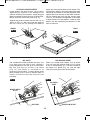
"!
The combination blade provided with your saw
is for both cross cuts and rip cuts. Ripping is
cutting lengthwise with the grain of the wood.
Rip cuts are easy to do with a rip fence
(Fig. 13). Rip Fence is available as an
accessory (not included). To attach fence, insert
fence through slots in foot to desired width as
shown and secure with the wing nut (not
included).
"
When rip cutting large sheets, the rip fence
may not allow the desired width of cut. Clamp
or nail a straight piece of 1" (25 mm) lumber to
the sheet as a guide (Fig. 14). Use the right
side of the foot against the board guide.
FIG. 13
RIP FENCE
DESIRED WIDTH
OF CUT
DESIRED LINE OF CUT
RIP BOARD
GUIDE
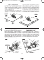
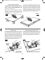
"!! !
Large sheets and long boards sag or bend,
depending on support. If you attempt to cut
without leveling and properly supporting the
piece, the blade will tend to bind, causing KICK-
BACK and extra load on the motor (Fig. 11).
Support the panel or board close to the cut, as
shown in (Fig. 12). Be sure to set the depth of
the cut so that you cut through the sheet or
board only and not the table or work bench. The
two-by-fours used to raise and support the work
should be positioned so that the broadest sides
support the work and rest on the table or bench.
Do not support the work with the narrow sides
as this is an unsteady arrangement. If the sheet
or board to be cut is too large for a table or work
bench, use the supporting two-by-fours on the
floor and secure.
RIGHT
FIG. 11
WRONG
FIG. 12
FIG. 14
SM 1619X04759 11-12_SM 1619X04759 11-12.qxp 11/20/12 2:05 PM Page 13

-14-
,9=0*,
9,=,5;0=, 4(05;,5(5*,
7,9-694,+)@<5(<;/690A,+
7,9:655,3 4(@ 9,:<3; 05 40:73(*05. 6-
05;,95(3 >09,: (5+ *64765,5;: >/0*/
*6<3+ *(<:, :,906<: /(A(9+ We
recommend that all tool service be performed
by a Skil Factory Service Center or
Autho rized Skil Service Station.
!"!
Your Skil tool has been properly lubricated and
is ready to use. However it is recommended
that the gears be relubricated only with Skil
lubricants: No. 80111 (8 oz. tube).
Always check the oil level before using the saw.
To check and add oil: Remove plug from power
source and place the saw’s foot on a horizontal
surface with tool set to maximum depth of cut.
Remove oil plug/lock button assembly using
the same wrench used to remove the saw
blade. The oil level should never be below
bottom threads in the housing. When adding
oil, fill until oil reaches bottom threads of the
housing. Do not over fill. Replace oil plug/lock
button assembly when finished (Fig. 15).
! If oil is dirty or thick, replace the oil
plug/lock button assembly and run the saw for
one minute to warm up the oil. Then remove oil
plug/lock button assembly and turn saw upside
down, to remove all oil. Add fresh Skil lubricant.
With a new saw, change the oil after the first
ten hours of use.
"
The brushes and commutator in your tool have
been engineered for many hours of
dependable service. To maintain peak
ef ficiency of the motor, we recommend every
two to six months the brushes be examined.
The brushes should be free from dust and dirt.
Brushes should be replaced when they have
worn down to 3/16" in length. The brushes
should slide freely in and out of the holders
without sticking.
To check brushes: Disconnect plug from
power source. Unscrew the brush caps on the
motor housing and lift out the brushes; note
which way they face, so that the brushes can
be returned to their original position. To
replace the blade side brush the tool needs to
be set to minimum depth of cut. Clean the
brush holder openings with com pressed air or
a clean cloth and replace the brushes and
caps.
Only genuine Skil replacement brushes
specially designed for your tool should be
used.
Bearings which become noisy (due to heavy
load or very abrasive material cut ting) should
be replaced at once to avoid overheating or
motor failure.
3,(505.
The tool may be cleaned most effectively with
compressed dry air. 3>(@: >,(9 :(-,;@
.6..3,: >/,5 *3,(505. ;663: >0;/
*6479,::,+(09
Ventilation openings and switch levers must
be kept clean and free of foreign matter. Do
not at tempt to clean by inserting pointed
objects through openings.
,9;(05 *3,(505. (.,5;:
(5+ :63=,5;: +(4(.,
73(:;0* 7(9;: Some of these are: gasoline,
carbon tetrachlo ride, chlo rinated cleaning
solvents, ammonia and house hold detergents
that contain ammonia.
(05;,5(5*,
!
CAUTION
!
WARNING
!6 (=60+ (**0+,5;: (3>(@: +0:*655,*; ;/, ;663 -964 ;/, 76>,9 :<773@
),-69,*3,(505.697,9-69405.(5@4(05;,5(5*,
!
WARNING
FIG. 15
OIL PLUG/LOCK
BUTTON ASSEMBLY
OIL LEVEL
INSTRUCTIONS
SM 1619X04759 11-12_SM 1619X04759 11-12.qxp 11/20/12 2:05 PM Page 14

-15-
**,::690,:
- (5 ,?;,5:065 *69+ 0:
5,*,::(9@ ( *69+ >0;/
(+,8<(;, :0A, *65+<*;69: ;/(; 0: *(7()3,
6-*(99@05.;/,*<99,5;5,*,::(9@-69@6<9
;663 4<:; ), <:,+ This will prevent
excessive voltage drop, loss of power or
overheating. Grounded tools must use 3-wire
extension cords that have 3-prong plugs and
receptacles.
!The smaller the gauge number, the
heav i er the cord.
' %!
#!!!"!!
!
WARNING
* Blade
* Wrench
** Carrying bag
** Adjustable Rip Fence
** Non-marring overshoe
(*= standard equipment)
(**= optional accessories)
The Model MAG77LT code 72 is equipped with
a “Twist-To-Lock” male connector as shown
(Fig. 16). Use only a 3-wire extension cord
which has a mating “Twist-To-Lock” female
connector on one end and a 3-prong grounding
plug on the other end. (See Electrical Safety
section on page 2 for grounding infor mation.)
!$ !!! !"!
!
&#!C!$ !!D
!663E:
47,9,
(;05.
69+ 0A,05$
$09, 0A,:0544
3-6
6-8
8-10
10-12
12-16
18 16 16 14 0.75 0.75 1.5 2.5
18 16 14 12 0.75 1.0 2.5 4.0
18 16 14 12 0.75 1.0 2.5 4.0
16 16 14 12 1.0 2.5 4.0 —
14 12 —— ————
25 50 100 150 15 30 60 120
69+,5.;/05,,; 69+,5.;/05,;,9:
?;,5:06569+:
The use of any other acces so ries not specified in this manual may create a hazard.
!
WARNING
Blades become dull even from cutting regular
lumber. If you find yourself forcing the saw
forward to cut instead of just guid ing it through
the cut, chances are the blade is dull or coated
with wood pitch.
When cleaning gum and wood pitch from
blade, unplug the saw and remove the blade.
Remember, blades are designed to cut, so
handle carefully. Wipe the blade with kerosene
or similar sol vent to remove the gum and pitch.
Unless you are experienced in sharpening
blades, we recommend you do not try.
FIG. 16
SM 1619X04759 11-12_SM 1619X04759 11-12.qxp 11/20/12 2:05 PM Page 15

-16-
!96<)3, /66;05.
Read instruction manual first! Remove plug from the power source before
making adjustments or assembling the blade.
!" $$! !!
1. Power cord is not plugged in.
2. Power source fuse or circuit breaker tripped.
3. Cord damaged.
4. Burned out switch.
5. Trigger does not turn tool on.
& 1. Plug saw in.
2. Replace fuse or reset tripped circuit breaker.
3. Inspect cord for damage. If damaged, have cord replaced by an Authorized Skil
Service Center or Service Station.
4. Have switch replaced by an Authorized Skil Service Center or Service Station.
5. Have switch replaced by an Authorized Skil Service Center or Service Station.
!" !"!
1. Extension cord too light or too long.
2. Low house voltage.
& 1. Replace with adequate cord.
2. Contact your electric company.
!"% ##!
1. Blade out of balance.
2. Workpiece not clamped or supported properly.
& 1. Discard Blade and use different blade.
2. Clamp or support workpiece as shown on pages 10 and 13.
!"! ""!$ "!!
1. Foot not adjusted properly.
& 1. See “Operating Instructions” section, “Bevel Adjustment” (page 10), “Line Guide”
(page 10, “Cutting Large Sheets (page 13) and “Rip Cuts” (page 13).
!""! " ! !$
1. Dull blade with improper tooth set.
2. Warped board.
3. Blade binds.
4. Improper workpiece support.
& 1. Discard blade and use a different blade.
2. Make sure concave or hollow side is facing “DOWN” feed slowly, see (page 13).
3. Assemble blade and tighten Vari-Torque clutch per “Assembly Instructions”, see
(page 9)
4. Clamp or support workpiece as shown on pages 10 and 13.
!"
1. Tool does not cut workpiece.
& 1. Assemble blade and tighten Vari-Torque clutch per “Assembly Instructions”, see
(page 9)
!
WARNING
SM 1619X04759 11-12_SM 1619X04759 11-12.qxp 11/20/12 2:05 PM Page 16

-17-
Veuillez lire tous les avertissements et toutes les consignes de sécurité. Si l'on
n'observe pas ces avertissements et ces consignes de sécurité, il existe un risque de
choc électrique, d'incendie et/ou de blessures corporelles graves.
CONSERVEZ TOUS LES AVERTISSEMENTS ET TOUTES LES CONSIGNES
DE SÉCURITÉ POUR RÉFÉRENCE FUTURE.
Dans les avertissements, le terme « outil électroportatif » se rapporte à votre outil branché sur le secteur (avec fil) ou
à votre outil alimenté par piles (sans fil).
Avertissements généraux concernant la sécurité des outils électroportatifs
AVERTISSEMENT
!
Sécurité du lieu de travail
Maintenez le lieu de travail propre et bien éclairé.
Les risques d’accident sont plus élevés quand on
travaille dans un endroit encombré ou sombre.
N’utilisez pas d’outils électroportatifs dans des
atmosphères explosives, comme par exemple en
présence de gaz, de poussières ou de liquides
inflammables. Les outils électroportatifs produisent
des étincelles qui risquent d’enflammer les poussières
ou les vapeurs.
Éloignez les enfants et les visiteurs quand vous vous
servez d’un outil électroportatif. Vous risquez une
perte de contrôle si on vous distrait.
Sécurité électrique
Les fiches des outils électroportatifs doivent
correspondre à la prise. Il ne faut absolument jamais
modifier la fiche. N’utilisez pas d’adaptateur de prise
avec des outils électroportatifs munis d’une fiche de
terre. Le risque de choc électrique est moindre si on
utilise une fiche non modifiée sur une prise qui lui
correspond.
Évitez tout contact du corps avec des surfaces reliées
à la terre tels que tuyaux, radiateurs, gazinières ou
réfrigérateurs. Le risque de choc électrique augmente
si votre corps est relié à la terre.
N’exposez pas les outils électroportatifs à la pluie ou
à l’humidité. Si de l’eau pénètre dans un outil
électroportatif, le risque de choc électrique augmente.
Ne maltraitez pas le cordon. Ne vous en servez
jamais pour transporter l’outil électroportatif, pour le
tirer ou pour le débrancher. Éloignez le cordon de la
chaleur, des huiles, des arêtes coupantes ou des
pièces mobiles. Les cordons abîmés ou emmêlés
augmentent les risques de choc électrique.
Si vous utilisez un outil électroportatif à l’extérieur,
employez une rallonge conçue pour l’extérieur. Ces
rallonges sont faites pour l’extérieur et réduisent le
risque de choc électrique.
S'il est absolument nécessaire d'utiliser l'outil
électroportatif dans un endroit humide, utilisez une
alimentation protégée par un disjoncteur de fuite de
terre (GFCI). L'utilisation d'un disjoncteur GFCI réduit
les risques de choc électrique.
Sécurité personnelle
Restez concentré, faites attention à ce que vous
faites, et servez-vous de votre bon sens lorsque vous
utilisez un outil électroportatif. N'employez pas
d’outils électroportatifs quand vous êtes fatigué ou
sous l’emprise de drogues, d’alcool ou de
médicaments. Quand on utilise des outils
électroportatifs, il suffit d’un moment d’inattention pour
causer des blessures corporelles graves.
Utilisez des équipements de sécurité personnelle.
Portez toujours une protection oculaire. Le port
d'équipements de sécurité tels que des masques
antipoussières, des chaussures de sécurité
antidérapantes, des casques de chantier et des
protecteurs d'oreilles dans des conditions appropriées
réduira le risque de blessure corporelle.
Évitez les démarrages intempestifs. Assurez-vous que
l'interrupteur est dans la position arrêt (Off) avant de
brancher l'outil dans une prise de courant et/ou un
bloc-piles, de le ramasser ou de le transporter. Le
transport d'un outil électroportatif avec le doigt sur la
gâchette ou le branchement de cet outil quand
l'interrupteur est en position de marche (ON) est une
invite aux accidents.
Enlevez toutes les clés de réglage avant de mettre
l’outil électroportatif en marche. Si on laisse une clé
sur une pièce tournante de l’outil électroportatif, il y a
risque de blessure corporelle.
Ne vous penchez pas. Conservez toujours une bonne
assise et un bon équilibre. Ceci vous permettra de
mieux maîtriser l’outil électroportatif dans des situations
inattendues.
Habillez-vous de manière appropriée. Ne portez pas
de vêtements amples ou de bijoux. Attachez les
cheveux longs. N’approchez pas les cheveux, les
vêtements ou les gants des pièces en mouvement.
Les vêtements amples, les bijoux ou les cheveux longs
risquent d’être happés par les pièces en mouvement.
Si l’outil est muni de dispositifs permettant le
raccordement d’un système d’aspiration et de
collecte des poussières, assurez-vous que ces
dispositifs sont raccordés et utilisés correctement.
L'utilisation d'un dépoussiéreur peut réduire les
dangers associés à l'accumulation de poussière.
SM 1619X04759 11-12_SM 1619X04759 11-12.qxp 11/20/12 2:05 PM Page 17

-18-
Utilisation et entretien des outils
électroportatifs
Ne forcez pas sur l’outil électroportatif. Utilisez l’outil
électroportatif qui convient à la tâche à effectuer.
L’outil qui convient à la tâche fait un meilleur travail et
est plus sûr à la vitesse pour lequel il a été conçu.
Ne vous servez pas de l’outil électroportatif si son
interrupteur ne parvient pas à le mettre en marche ou
à l’arrêter. Tout outil électroportatif qui ne peut pas
être commandé par son interrupteur est dangereux et
doit être réparé.
Débranchez la fiche de la prise ou enlevez le bloc-
pile de l’outil électroportatif avant tout réglage,
changement d’accessoires ou avant de ranger l’outil
électroportatif. De telles mesures de sécurité
préventive réduisent le risque de démarrage intempestif
de l’outil électroportatif.
Rangez les outils électroportatifs dont vous ne vous
servez pas hors de portée des enfants et ne permettez
pas à des personnes qui ne connaissent pas l’outil
électroportatif ou qui ignorent ces consignes de s’en
servir. Les outils électroportatifs sont dangereux dans
les mains d’utilisateurs inexpérimentés.
Entretenez les outils électroportatifs. Vérifiez que les
pièces mobiles sont alignées correctement et ne
coincent pas. Vérifiez qu’il n’y a pas de pièces
cassées ou d’autre circonstance qui risquent
d’affecter le fonctionnement de l’outil électroportatif.
Si l’outil est abîmé, faites-le réparer avant de
l’utiliser. De nombreux accidents sont causés par des
outils électroportatifs mal entretenus.
Maintenez les outils coupants affûtés et propres. Les
outils coupants entretenus correctement et dotés de
bords tranchants affûtés sont moins susceptibles de
coincer et sont plus faciles à maîtriser.
Utilisez l'outil électroportatif, les accessoires et les
embouts d'outil, etc. conformément à ces
instructions, en tenant compte des conditions de
travail et des travaux à réaliser. L'emploi d’outils
électroportatifs pour des tâches différentes de celles
pour lesquelles ils ont été prévus peut résulter en une
situation dangereuse.
Entretien
Faites réparer votre outil électroportatif par un agent
de service qualifié n’utilisant que des pièces de
rechange identiques. Ceci assure que la sécurité de
l’outil électroportatif est préservée.
Consignes de sécurité pour scies circulaires
Procédures de coupe
Tenez les mains à l'écart de l'aire
de coupe et de la lame. Gardez
votre deuxième main sur la poignée auxiliaire ou le
carter du moteur. Quand les mains tiennent la scie,
elles ne peuvent pas être coupées par la lame.
N'introduisez pas la main sous la pièce à travailler.
Le garde ne peut pas vous protéger de la lame sous la
pièce à travailler.
Ajustez la profondeur de coupe en fonction de
l'épaisseur de la pièce à travailler. Il doit seulement
être possible de voir moins d'une dent complète des
dents de la lame au-dessous de la pièce à travailler.
Ne tenez jamais la pièce à couper dans vos mains ou
sur vos jambes. Fixez la pièce à travailler sur une
plateforme stable. Il importe de supporter l'ouvrage
adéquatement afin de minimiser l'exposition corporelle,
le grippage de lame ou la perte de contrôle.
Tenez l'outil électroportatif par les surfaces isolées de
préhension quand vous effectuez une opération au
cours de laquelle l'outil de coupe peut venir en
contact avec des fils dissimulés ou son propre
cordon. Le contact avec un fil sous tension rendra
également les parties métalliques exposées de l'outil
sous tension et de causer un choc électrique à
l'opérateur.
En refendant, utilisez toujours un guide de refente ou
une règle. Ceci améliore l'exactitude de la coupe et
réduit les possibilités de grippage de la lame.
Utilisez toujours des lames avec trous d'arbre de la
dimension et de la forme appropriées (en diamant par
rapport à rondes). Les lames qui ne se marient pas
avec le système de montage de la scie ne tourneront
pas rond. Il en résultera une perte de contrôle.
N'utilisez jamais des rondelles ou boulon de lame
abîmés ou incorrects. Les rondelles et le boulon de
lame ont été conçus spécialement pour votre scie, pour
une performance optimale et pour un fonctionnement
des plus sûrs.
Inspectez la condition et la qualité du bois et si vous
trouvez des clous, retirez-les avant de couper. Le bois
mouillé, le bois vert ou le bois traité par pression
nécessitent une attention spéciale durant la coupe pour
prévenir le rebond.
Tenez la scie fermement pour prévenir une perte de
contrôle. Les figures de ce manuel illustrent le support
manuel typique de la scie.
Suivant l'usage, l'interrupteur peut ne pas durer aussi
longtemps que la scie. Si l'interrupteur fait défaut en
position d'arrêt, la scie peut ne pas se mettre en
marche. S'il devient défectueux pendant que la scie
DANGER
!
Veuillez lire tous les avertissements et toutes les consignes de sécurité.
AVERTISSEMENT
!
SM 1619X04759 11-12_SM 1619X04759 11-12.qxp 11/20/12 2:05 PM Page 18

-19-
est en marche, la scie peut ne pas s'arrêter. Dans l'un
ou l'autre cas, débranchez la scie immédiatement et ne
l'utilisez pas avant qu'elle ne soit réparée.
Cette scie circulaire ne doit pas être montée sur une
table et convertie en scie de table. Les scies
circulaires ne sont pas conçues ni destinées à être
utilisées comme scies de table.
Causes des rebonds et
avertissements associés
Le rebond est une réaction soudaine à une lame de scie
pincée, grippée ou mal alignée, amenant ainsi la scie
non contrôlée à lever et ressortir de l'ouvrage en
direction de l'opérateur.
Lorsque la lame est pincée ou grippée fermement par le
trait de scie qui se referme, la lame bloque et la réaction
du moteur ramène rapidement l'outil en direction de
l'opérateur.
Si la lame devient tordue ou mal alignée dans la coupe,
les dents du bord arrière de la lame peuvent s'enfoncer
dans la surface supérieure du bois, amenant ainsi la
lame à sortir du trait de scie et à revenir vers
l'opérateur.
Le rebond est le résultat d'une utilisation erronée de
l'outil et/ou de méthodes ou de conditions de
fonctionnement incorrectes, et on peut l'éviter en
prenant les précautions appropriées, comme indiqué ci-
après :
Maintenez une prise ferme avec les deux mains sur la
scie et positionnez vos bras de manière à résister aux
forces de rebond. Positionnez votre corps d’un côté
ou de l’autre de la lame, mais pas dans la trajectoire
de la lame. Le rebond peut faire que la lame saute en
arrière, mais l'opérateur peut contrôler les forces de
rebond en prenant les précautions appropriées.
Lorsque la lame grippe ou lorsqu'une coupe est
interrompue pour quelque motif que ce soit, relâchez
la gâchette et tenez la scie sans bouger dans
l'ouvrage jusqu'à ce que la lame s'arrête
complètement. Ne tentez jamais de retirer la scie de
l'ouvrage ou de tirer la scie vers l'arrière pendant que
la lame est en mouvement, ce qui pourrait provoquer
un rebond. Recherchez la cause du grippage de lame et
prenez les mesures nécessaires pour le corriger.
Lorsque vous remettez une scie en marche dans un
ouvrage, centrez la lame de scie dans le trait de scie
et assurez-vous que les dents de scie ne sont pas
engagées dans l'ouvrage. Si la lame de scie grippe,
elle peut remonter ou rebond depuis l'ouvrage lorsque
la scie est remise en marche.
Supportez les gros panneaux pour minimiser le risque
de pincement de lame et de rebond. Les gros
panneaux ont tendance à s'affaisser sous leur propre
poids. Des supports doivent être placés sous le
panneau des deux côtés, près de la ligne de coupe et
près du bord du panneau.
N'utilisez pas une lame émoussée ou abîmée. Les
lames non affûtées ou réglées de façon inappropriée
produisent un trait de scie étroit, ce qui cause une
friction excessive, un grippage de lame et un rebond.
Les leviers de blocage de réglage de biseau et de
profondeur de lame doivent être serrés et fermes
avant de pratiquer la coupe. Un déplacement du
réglage de lame durant la coupe peut causer un
grippage et un rebond.
Redoubler de prudence en pratiquant une opérations
de sciage dans des murs existants ou autres parties
aveugles. La lame faisant saillie peut couper des objets
qui peuvent causer un rebond.
Les rondelles de lame et le boulon sur votre scie ont
été conçus de manière à travailler comme un
embrayage pour réduire l’intensité des rebonds.
Comprenez le fonctionnement et les réglages de
l'EMBRAYAGE À COUPLE VARIABLE. Le réglage
approprié de l'embrayage, combiné au maniement
ferme de la scie, vous permettra de contrôler le rebond.
Ne placez jamais votre main derrière la lame de la
scie. Le rebond pourrait faire sauter la scie vers l'arrière
par-dessus votre main.
N’utilisez pas la scie avec un réglage excessif de
profondeur de coupe. Une exposition excessive de la
lame accroît la possibilité de torsion de la lame dans le
trait de scie. Elle accroît également la surface de lame
pouvant être pincée, ce qui entraînerait un rebond.
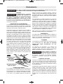
Fonction du garde inférieur
Vérifiez le garde inférieur pour vous assurer qu'il
ferme adéquatement avant chaque usage. N'utilisez
pas la scie si le garde inférieur ne bouge pas
librement et ne ferme pas instantanément. Ne pincez
ou ne fixez jamais le garde inférieur en position
ouverte. Si la scie tombe par mégarde, le garde
inférieur peut être plié. Levez le garde inférieur
uniquement à l'aide de la levier de levage du garde
EMBRAYAGE
VARI-TORQUE
REBOND
SM 1619X04759 11-12_SM 1619X04759 11-12.qxp 11/20/12 2:05 PM Page 19

-20-
Avertissements supplémentaires concernant la sécurité
L’emploi d’un GFCI et de dispositifs de protection
personnelle tels que gants et chaussures d’électricien en
caoutchouc améliorent votre sécurité personnelle.
N’utilisez pas un outil conçu uniquement pour le C.A.
sur une alimentation en C.C. Même si l’outil semble
fonctionner, les composants électriques d’un outil prévu
pour le C.A. tomberont probablement en panne et
risquent de créer un danger pour l’utilisateur.
Maintenez les poignées sèches et exemptes d’huile et
de graisse. On ne pas maîtriser un outil électroportatif
en toute sécurité quand on a les mains glissantes.
Utilisez des brides ou d’autres moyens pratiques de
brider ou de supporter la pièce sur une plate-forme
stable. Tenir la pièce à la main ou contre le corps est
instable et risque de résulter en une perte de contrôle.
Créez un agenda d’entretien périodique pour votre
outil. Quand vous nettoyez un outil, faites attention
de n’en démonter aucune pièce car il est toujours
possible de mal remonter ou de pincer les fils
internes ou de remonter incorrectement les ressorts
de rappel des capots de protection. Certains agents
de nettoyage tels que l’essence, le tétrachlorure de
carbone, l’ammoniaque, etc. risquent d’abîmer les
plastiques.
Risque de blessure pour l'utilisateur. Le cordon
d'alimentation électrique ne doit être réparé que par un
Centre de service usine de Skil ou par une Station
service agréée de Skil.
Les travaux à la machine
tel que ponçage, sciage,
meulage, perçage et autres travaux du bâtiment
peuvent créer des poussières contenant des produits
chimiques qui sont des causes reconnues de cancer,
de malformation congénitale ou d’autres problèmes
reproductifs. Ces produits chimiques sont, par
exemple :
• Le plomb provenant des peintures à base de plomb,
• Les cristaux de silices provenant des briques et du
ciment et d’autres produits de maçonnerie, et
• L’arsenic et le chrome provenant des bois traités
chimiquement.
Le niveau de risque dû à cette exposition varie avec la
fréquence de ces types de travaux. Pour réduire
l’exposition à ces produits chimiques, il faut travailler
dans un lieu bien ventilé et porter un équipement de
sécurité approprié tel que certains masques à poussière
conçus spécialement pour filtrer les particules
microscopiques.
AVERTISSEMENT
!
inférieur, et assurez-vous qu'il bouge librement et ne
vient pas en contact avec la lame ou aucune autre pièce,
sous tous les angles et profondeurs de coupe.
Vérifiez le fonctionnement du ressort du rappel du
garde inférieur. Si le garde et le ressort ne
fonctionnent pas adéquatement, ils doivent être
réparés avant usage. Le garde inférieur peut
fonctionner paresseusement en raison de pièces
abîmées, de dépôts gommeux ou d'une accumulation
de débris.
Le garde inférieur doit être rétracté manuellement
uniquement pour des coupes spéciales telles que les
« coupes en guichet » et les « coupes combinées ».
Levez le garde inférieur à l'aide du levier de levage du
garde inférieur. Le garde inférieur doit être relâché dès
que la lame pénètre dans l'ouvrage. Pour toutes les
autres opérations de sciage, le garde inférieur doit
fonctionner automatiquement.
Assurez-vous toujours que le garde inférieur couvre la
lame avant de déposer la scie sur l'établi ou le
plancher. Une lame non protégée, qui continue à
marcher par inertie, fera reculer la scie, coupant ainsi
tout ce qui est sur son chemin. Sachez le temps qu'il
faut pour que la lame s'arrête après relâchement de
l'interrupteur.
Ne faites pas fonctionner l’outil quand vous le portez
sur votre hanche. Le garde inférieur peut s'ouvrir au
contact avec vos vêtements. Un contact accidentel
avec la lame de scie en rotation pourrait provoquer des
blessures graves.
À intervalles périodiques, déposez la lame, nettoyez
les gardes supérieur et inférieur et la région du
moyeu à l'aide de kérosène et essuyez pour sécher,
ou nettoyez en soufflant de l'air comprimé. Une
maintenance préventive et une utilisation correcte du
garde réduiront la probabilité d’un accident.
SM 1619X04759 11-12_SM 1619X04759 11-12.qxp 11/20/12 2:05 PM Page 20
La page est en cours de chargement...
La page est en cours de chargement...
La page est en cours de chargement...
La page est en cours de chargement...
La page est en cours de chargement...
La page est en cours de chargement...
La page est en cours de chargement...
La page est en cours de chargement...
La page est en cours de chargement...
La page est en cours de chargement...
La page est en cours de chargement...
La page est en cours de chargement...
La page est en cours de chargement...
La page est en cours de chargement...
La page est en cours de chargement...
La page est en cours de chargement...
La page est en cours de chargement...
La page est en cours de chargement...
La page est en cours de chargement...
La page est en cours de chargement...
La page est en cours de chargement...
La page est en cours de chargement...
La page est en cours de chargement...
La page est en cours de chargement...
La page est en cours de chargement...
La page est en cours de chargement...
La page est en cours de chargement...
La page est en cours de chargement...
-
 1
1
-
 2
2
-
 3
3
-
 4
4
-
 5
5
-
 6
6
-
 7
7
-
 8
8
-
 9
9
-
 10
10
-
 11
11
-
 12
12
-
 13
13
-
 14
14
-
 15
15
-
 16
16
-
 17
17
-
 18
18
-
 19
19
-
 20
20
-
 21
21
-
 22
22
-
 23
23
-
 24
24
-
 25
25
-
 26
26
-
 27
27
-
 28
28
-
 29
29
-
 30
30
-
 31
31
-
 32
32
-
 33
33
-
 34
34
-
 35
35
-
 36
36
-
 37
37
-
 38
38
-
 39
39
-
 40
40
-
 41
41
-
 42
42
-
 43
43
-
 44
44
-
 45
45
-
 46
46
-
 47
47
-
 48
48


Skil MAG77LT Manuel utilisateur
- Catégorie
- Outils électroportatifs
- Taper
- Manuel utilisateur
- Ce manuel convient également à
dans d''autres langues
- English: Skil MAG77LT User manual
- español: Skil MAG77LT Manual de usuario
Documents connexes
-
Skil SPT70WM-01 Manuel utilisateur
-
-
-
-
-
-
-
-
-