Miller KE621826 Le manuel du propriétaire
- Catégorie
- Système de soudage
- Taper
- Le manuel du propriétaire
Ce manuel convient également à

Miller
April
1994
Form:
OM-1583D
Effective
With
Serial
No.
KE621
826
~11c~
~''
c~r~1
OWNERS
MANUAL
Read
and
follow
these
instructions
and
all
safety
blocks
carefully.
Have
only
trained
and
qualified
persons
install,
operate,
or
service
this
unit.
Call
your
distributor
if
you
do
not
understand
the
directions.
SWINGARCTM
SS-12
And
SS-16
24
Volts,
10
Amperes,
50/60
Hertz
Boom
Mounted
Wire
Feeder
For
Use
With
CV/DC
Welding
Power
Source
With
Contactor
For
GMAW
And
FCAW
Welding
Rated
At
100
Volts,
750
Amperes,
100%
Duty
Cycle
Wire
Feed
Speed
Range:
50
To
780
ipm
(1.3
To
19.8
mpm)
Wire
Diameter
Range:
.023
To
1/8
in
(0.6
To
3.2
mm)
Vertical
Lift
Of
Boom:
Horizontal
To
600
Above
Horizontal
See
Rear
Cover
For
Options
And
Accessories
U
U
U
Give
this
manual
to
the
operator.
For
help,
call
your
distributor
or:
MILLER
Electric
Mfg.
Co.,
P.O.
Box
1079,
Appleton,
WI
54912
414-734-9821
cover
1/94
ST-142
705-B
'
1994
MILLER
Electflc
Mfg.
Co.
PRINTED
IN
USA

Ui___________________
---
________________
I
MILLERS
TRUE
BLUETM
LIMITED
WARRANTY
Effective
January
1,
1992
(Equipment
with
a
serial
number
preface
of
KC
or
newer)
This
limited
warranty
supersedes
att
previous
MILLER
warrenties
and
is
exclusive
with
no
other
guarantees
or
wsrranties
espressed
or
implied.
LIMITED
WARRANTY
Subject
to
the
terms
end
conditions
betow,
MILLER
Electric
Mtg.
Co.,
Appleton,
Wisconsin,
werrents
to
its
original
retsil
purcheser
thet
new
MILLER
equipment
sold
after
the
effective
date
ot
this
limited
warranty
is
free
of
de
fects
in
material
snd
workmanship
et
the
time
it
is
shipped
by
MtLLER.
THIS
WAR
RANTY
IS
EXPRESSLY
IN
LIEU
OF
ALL
OTHER
WARRANTIES,
EXPRESS
OR
IMPLIED,
INCLUDING
THE
WARRANTIES
OF
MERCHANTABILITY
AND
FIT
NESS.
Within
the
wsrranty
periods
listed
below,
MILLER
wilt
repair
or
replace
any
war
ranted
parta
or
components
that
tail
due
to
auch
defects
in
material
orwoilimanahip.
MILLER
must
be
notified
in
writing
within
thirty
(30)
days
of
such
detect
or
failure,
at
which
time
MILLER
wilt
provide
instructions
on
the
warranty
claim
procedurea
to
be
followed.
MILLER
shalt
honor
warranty
claims
on
warranted
equipment
hated
below
in
the
event
ot
such
a
failure
within
the
warranty
time
periods.
All
warranty
time
perioda
alan
on
the
date
that
the
equipment
was
delivered
to
the
originst
retail
purchaser,
or
one
year
efter
the
equipment
is
sent
to
the
distributor.
5
Years
Parts
3
Years
Labor
Original
main
power
rectifiers
2.
3 Years
Parts
and
Labor
Transformer/Rectifier
Power
Sources
Plasma
Arc
Cuning
Power
Sources
Semi-Automatic
and
Automatic
Wire
Feeders
Robots
3.
2
Years
Parts
and
Labor
Engine
Driven
Welding
Generators
(NOTE:
Engines
are
warranted
aeparalely
by
the
engine
manufacturer
for
a
period
of
two
years.)
Air
Compreaaors
4.
1
Year
Parts
and
Labor
*
Motor
Driven
Guns
Process
Controllers
Water
Coolant
Syatema
HF
Units
Grids
Spot
Welders
Load
Banks
SDX
Transformers
Running
Gear/Trailera
Field
Options
(NOTE:
Field
options
are
covered
under
True
BIueTM
for
the
remaining
warranty
period
of
the
product
they
are
metalled
in,
or
fore
minimum
of
one
year
whichever
is
greater.)
6
Months
Batteries
90
Days
Perle
end
Labor
MIG
Guns/TIG
Torches
Plasma
Cutting
Torches
Remote
Controls
Accessory
Kits
Replacement
Parts
MILLERS
True
BIueTM
Limited
Warranty
shell
not
apply
to:
1.
Items
tumished
by
MILLER,
but
menutectured
by
others,
such
as
engines
or
trade
ecceesoriee.
These
items
are
covered
by
the
manufacturers
warranty,
it
any.
2.
Consumable
components;
such
as
contact
tips,
cutting
nozzes,
contactors
end
relays
or
parts
that
fail
due
to
normel
wear.
3.
Equipment
that
has
been
modified
by
any
party
other
than
MILLER,
or
equip
ment
that
has
been
improperly
installed,
improperty
operated
or
misused
based
upon
industry
standards,
or
equipment
which
has
not
had
reasonable
end
necesasry
maintenance,
or
equipment
which
has
been
used
for
operation
outside
of
the
specifications
for
I
he
equipment.
MILLER
PRODUCTS
ARE
INTENDED
FOR
PURCHASE
AND
USE
BY
COMMER
CIAL/INDUSTRIAL
USERS
AND
PERSONS
TRAINED
AND
EXPERIENCED
IN
THE USE
AND
MAINTENANCE
OF
WELDING
EOUIPMENT.
In
the
event
of
e
warranty
claim
covered
by
this
werranty,
the
exclusive
remsdies
shell
be,
at
MILLERS
option:
(1)
repair;
or
(2)
replacement;
or,
where
authorized
in
writing
by
MtLLER
in
eppropriale
cases,
(3)
the
reasonable
coal
of
repair
or
replace
ment
stan
authorized
MILLER
seivice
elation;
or
(4)
payment
of
or
ci
edit
for
the
pur
chase
price
(less
reasonable
depreciation
based
upon
actual
use)
upon
return
of
the
goods
el
customers
risk
and
expense.
MILLERS
option
of
repair
or
replacement
wilt
be
FOB.,
Feclory
at
Appleton,
Wisconsin,
or
FOB.
eta
MILLER
authorized
ser
vice
facility
as
determined
by
MILLER.
Therefore
no
compensation
or
reimburse
ment
for
Irensportetion
costs
ot
any
kind
will
be
allowed.
TO
THE
EXTENT
PERMtTTED
BY
LAW,
THE
REMEDIES
PROV:DED
HEREIN
ARE
THE
SOLE
AND
EXCLUStVE
REMEDIES.
IN
NO
EVENT
SHALL
MILLER
BE
LIABLE
FOR
DIRECT
INDIRECT,
SPECIAL,
INCIDENTAL
OR
CONSEOUENTIAL
DAMAGES
(INCLUDING
LOSS
OF
PROFIT),
WHETHER
BASED
ON
CON
TRACT,
TORT
OR
ANY
OTHER
LEGAL
THEORY.
ANY
EXPRESS
WARRANTY
NOT
PROVIDED
HEREIN
AND
ANY
IMPLIED
WAR
RANTY,
GUARANTY
OR
REPRESENTATION
AS
TO
PERFORMANCE,
AND
ANY
REMEDY
FOR
BREACH
OF
CONTRACT
TORT
OR
ANY
0
IHER
LEGAL
THEORY
WHICH,
BUT
FOR
THIS
PROVISION,
MIGHT
ARISE
BY
IMPLICATION,
OPERATION
OF
LAW,
CUSTOM
OF
TRADE
OR
COURSE
OF
DEALING,
IN
CLUDING
ANY
IMPLIED
WARRANTY
OF
MERCHANTABILITY
OR
FITNESS
FOR
PARTICULAR
PURPOSE,
WITH
RESPECT
TO
ANY
AND
ALL
EOUIPMENT
FURNISHED
BY
MILLER
IS
EXCLUDED
AND
DISCLAIMED
BY
MILLER.
Some
stales
in
the
U.S.A.
do
not
ellow
limitations
of
how
long
an
implied
warranty
lasts,
or
the
exclusion
of
incidental,
indirect,
special
or
consequential
damages,
so
the
ebove
limitation
or
exclusion
may
not
apply
to
you.
This
warranty
provides
ape
citic
legal
rights,
end
other
rights
may
be
available,
but
may
very
from
stale
to
stale.
In
Canada,
legislation
in
some
provinces
provides
for
certain
additional
warranties
or
remedies
other
than
as
staled
herein,
end
to
the
extent
that
they
may
not
be
waived,
the
limitations
end
exclusions
set
out
above
mey
not
eppiy.
This
Limited
Warrenty
provides
specific
legal
rights,
end
other
rights
may
be
available,
but
may
vary
from
province
to
province.
Li
5.
6.
~~1
xwd,
RECEIVING-HANDLING
Before
unpacking
equipment,
check
carton
for
any
damage
that
may
have
occurred
during
shipment.
File
any
claims
for
loss
or
damage
with
the
delivering
carrier.
Assistance
for
filing
or
settling
claims
may
be
obtained
from
distributor
and/or
equipment
manufacturers
Transportation
Department.
When
requesting
information
about
this
equipment,
always
provide
Model
Designation
and
Serial
or
Style
Number.
Use
the
following
spaces
to
record
Model
Designation
and
Serial
or
Style
Number
of
your
unit.
The
information
is
located
on
the
rating
label
or
nameplate.
Model
_________
Serial
or
Style
No.
Date
of
Purchase
miller
9/93

ERRATA
SHEET
-
June
1,
1994
FORM:
OM-1583D
Use
above
FORM
number
when
ordering
extra
manuals.
After
this
manual
was
printed,
refinements
in
equipment
design
occurred.
This
sheet
lists
exceptions
to
data
appearing
later
in
this
manual.
CHANGES
TO
SECTION
7
PARTS
LIST
Change
Parts
List
as
follows:
Part
Replaced
**
No.
With
Description
Quantity
43-16
..
133
603
...
165
934
..
SPRING,
cprsn
.573
OD
x
.088
wire
x
1.062
Ig
(Eff
w/KE644333)
..
1
43-
Added
...
165
799
..
WASHER,
flat
.257
ID
stl
(Elf
w/KE644333)
1
43-
Added
...
165
798
..
SPRING,
pressure
arm
retaining
(Elf
w/KE644333)
1
43-
Added
...
.163
282
..
NUT,
.250-28
stl
(Elf
w/KE644333)
1
**First
digit
represents
page
no
digits
following
dash
represent
item
no.
BE
SURE
TO
PROVIDE
MODEL
AND
SERIAL
NUMBER
WHEN
ORDERING
REPLACEMENT
PARTS.
F~LE
COPY
~E1U~
TO
~OLOER


ARC
WELDING
SAFETY
PRECAUTIONS
ELECTRIC
SHOCK
can
kill.
Touching
live
electrical
parts
can
cause
fatal
shocks
or
severe
burns.
The
electrode
and
work
circuit
is
electrically
live
whenever
the
output
is
on.
The
input
power
circuit
and
machine
internal
circuits
are
also
live
when
power
is
on.
In
semiautomatic
or
automatic
wire
welding,
the
wire,
wire
reel,
drive
roll
housing,
and
all
metal
parts
touching
the
welding
wire
are
electrically
live.
Incorrectly
installed
or
improperly
grounded
equipment
is
a
hazard.
1.
Do
not
touch
live
electrical
parts.
2.
Wear
dry,
hole-free
insulating
gloves
and
body
protection.
3.
Insulate
yourself
from
work
and
ground
using
dry
insulating
mats
or
covers.
4.
Disconnect
input
power
or
stop
engine
before
installing
or
servicing
this
equipment.
5.
Properly
install
and
ground
this
equipment
according
to
its
Owners
Manual
and
national,
state,
and
local
codes.
6.
When
making
input
connections,
attach
proper
grounding
conductor
first.
7.
Turn
off
all
equipment
when
not
in
use.
8.
Do
not
use
worn,
damaged,
undersized,
or
poorly
spliced
cables.
Do
not
wrap
cables
around
your
body.
Ground
the
workpiece
to
a
good
electrical
(earth)
ground.
11.
Do
not
touch
electrode
if
in
contact
with
the
work
or
ground.
12.
Use
only
well-maintained
equipment.
Repair
or
replace
damaged
parts
at
once.
13.
Wear
a
safety
harness
if
working
above
floor
level.
14.
Keep
all
panels
and
covers
securely
in
place.
a
WARNING
ARC
WELDING
can
be
hazardous.
PROTECT
YOURSELF
AND
OTHERS
FROM
POSSIBLE
SERIOUS
INJURY
OR
DEATH.
KEEP
CHILDREN
AWAY.
PACEMAKER
WEARERS
KEEP
AWAY
UNTIL
CONSULTING
YOUR
DOCTOR.
In
welding,
as
in
most
jobs,
exposure
to
certain
hazards
occurs.
Welding
is
safe
when
precautions
are
taken.
The
safety
information
given
below
is
only
a
summary
of
the
more
complete
safety
information
that
will
be
found
in
the
Safety
Standards
listed
on
the
next
page.
Read
and
follow
all
Safety
Standards.
HAVE
ALL
INSTALLATION,
OPERATION,
MAINTENANCE,
AND
REPAIR
WORK
PERFORMED
ONLY
BY
QUALIFIED
PEOPLE.
-
9.
10.
ARC
RAYS
can
burn
eyes
and
skin;
~
NOISE
can
damage
hearing.
Arc
rays
from
the
welding
process
produce
intense
heat
and
strong
ultraviolet
rays
that
can
burn
eyes
and
skin.
Noise
from
some
processes
can
damage
hearing.
NOISE
1.
Use
approved
ear
plugs
or
ear
muffs
if
noise
level
is
high.
ARC
RAYS
2.
Wear
a
welding
helmet
fitted
with
a
proper
shade
of
filter
(see
ANSI
Z49.
I
listed
in
Safety
Standards)
to
protect
your
face
and
eyes
when
welding
or
watching.
3.
Wear
approved
safety
glasses.
Side
shields
recommended.
4.
Use
protective
screens
or
barriers
to
protect
others
from
flash
and
glare;
warn
others
not
to
watch
the
arc.
5.
Wear
protective
clothing
made
from
durable,
flame-resistant
material
(wool
and
leather)
and
foot
protection.
FUMES
AND
GASES
can
be
hazardous
5.
Work
in
a
confined
space
only
if
it
is
well
ventilated,
or
while
to
your
health.
wearing
an
air-supplied
respirator.
Shielding
gases
used
for
Weldingproducesfumesandgases.
Breathingthese
fumes
and
gases
can
be
hazardous
to
your
health.
welding
can
displace
air
causing
injury
or
death.
Be
sure
the
breathing
air
is
safe.
1.
Keep
your
head
out
of
the
fumes.
Do
not
breathe
the
fumes.
2.
If
inside,
ventilate
the
area
and/or
use
exhaust
at
the
arc
to
remove
welding
fumes
and
gases.
3.
If
ventilation
is
poor,
use
an
approved
air-supplied
respirator.
4.
Read
the
Material
Safety
Data
Sheets
(MSDS5)
and
the
manufacturers
instruction
for
metals,
consumables,
coatings,
and
cleaners,
WELDING
can
cause
fire
or
explosion.
Sparks
and
spatter
fly
off
from
the
welding
arc.
The
flying
sparks
and
hot
metal,
weld
spatter,
hot
workpiece,
and
hot
equipment
can
cause
fires
and
burns.
Accidental
contact
of
electrode
orwelding
wire
to
metal
objects
can
cause
sparks,
overheating,
or
fire.
1.
Protect
yourself
and
others
from
flying
sparks
and
hot
metal,
2.
Do
not
weld
where
flying
sparks
can
strike
flammable
material.
3.
Remove
all
flammables
within
35
ft
(10.7
m)
of
the
welding
arc.
If
this
is
not
possible,
tightly
cover
them
with
approved
covers,
4.
Be
alert
that
welding
sparks
and
hot
materials
from
welding
can
easily
go
through
small
cracks
and
openings
to
adjacent
areas.
6.
7.
5.
6.
7.
8.
9.
10.
11.
Do
not
weld
in
locations
near
degreasirig,
cleaning,
or
spraying
operations.
The
heat
and
rays
of
the
arc
can
react
with
vapors
to
form
highly
toxic
and
irritating
gases.
Do
not
weld
on
coated
metals,
such
as
galvanized,
lead,
or
cadmium
plated
steel,
unless
the
coating
is
removed
from
the
weld
area,
the
area
is
well
ventilated,
and
if
necessary,
while
wearing
an
air-supplied
respirator.
The
coatings
and
any
metals
containing
these
elements
can
give
off
toxic
fumes
if
welded.
Watch
for
fire,
and
keep
a
fire
extinguisher
nearby.
Be
aware
that
welding
on
a
ceiling,
floor,
bulkhead,
or
partition
can
cause
fire
on
the
hidden
side.
Do
not
weld
on
closed
containers
such
as
tanks
or
drums.
Connect
work
cable
to
the
work
as
close
to
the
welding
area
as
practical
to
prevent
welding
current
from
traveling
long,
possibly
unknown
paths
and
causing
electric
shock
and
fire
hazards.
Do
not
use
welder
to
thaw
frozen
pipes.
Remove
stick
electrode
from
holder
or
cut
off
welding
wire
at
contact
tip
when
not
in
use.
Wearoil.free
protective
garments
such
as
leather
gloves,
heavy
shirt,
cuffless
trousers,
high
shoes,
and
a
cap.
FLYING
SPARKS
AND
HOT
METAL
can
I
cause
injury,
I
I
Chipping
and
grinding
cause
flying
metal.
As
welds
cool,
they
can
throw
off
slag.
1.
2.
Wear
approved
face
shield
or
safety
goggles.
Side
shields
recommended.
Wear
proper
body
protection
to
protect
skin.
Sri
9/92

.
1.
J
CYLINDERS
can
explode
if
damaged.
..
~
~
Shielding
gas
cylinders
contain
gas
under
high
~.z
pressure.
If
damaged,
a
cylinder
can
explode.
Since
~
gas
cylinders
are
normally
part
of
the
welding
process,
be
sure
to
treat
them
carefully,
Protect
compressed
gas
cylinders
from
excessive
heat,
mechanical
shocks,
and
arcs.
3.
4.
5.
6.
7.
Keep
cylinders
away
from
any
welding
or
other
electrical
circuits.
Never
allow
a
welding
electrode
to
touch
any
cylinder.
Use
only
correct
shielding
gas
cylinders,
regulators,
hoses,
and
fittings
designed
for
the
specific
application;
maintain
them
and
associated
parts
in
good
condition.
Turn
face
away
from
valve
outlet
when
opening
cylinder
valve.
Keep
protective
cap
in
place
over
valve
except
when
cylinder
is
in
use
or
connected
for
use.
2.
Install
and
secure
cylinders
in
an
upright
position
by
chaining
them
to
a
stationary
support
or
equipment
cylinder
rack
to
prevent
falling
or
tipping.
8.
Read
and
follow
instructions
on
compressed
gas
cylinders,
associated
equipment,
and
CGA
publication
P-i
listed
in
Safety
Standards.
a
WARNING
A
ENGINE
EXHAUST
GASES
can
kill.
PRINCIPAL
SAFETY
STANDARDS
Safety
in
Welding
and
Cutting,
ANSI
Standard
Z49.1,
from
American
Welding
Society.
550
N.W.
LeJeune
Rd.
Miami
FL
33126
Safety
and
Health
Standards,
OSHA
29
CFR
1910,
from
Superinten.
dent
of
Documents,
U.S.
Government
Printing
Office,
Washington,
D.C.
20402.
Recommended
Safe
Practices
for
the
Preparation
for
Welding
and
Cutting
of
Containers
That
Have
Held
Hazardous
Substances,
Ameri
can
Welding
Society
Standard
AWS
F4.i
,from
American
Welding
So
ciety,
550
N.W.
LeJeune
Rd, Miami,
FL
33126
National
Electrical
Code,
NFPA
Standard
70,
from
National
Fire
Pro
tection
Association,
Batterymarch
Park,
Quincy,
MA
02269.
Safe
Handling
of
Compressed
Gases
in
Cylinders,
CGA
Pamphlet
P-i,
from
Compressed
Gas
Association,
1235
Jefferson
Davis
High
way,
Suite
501,
Arlington,
VA
22202.
Code
for
Safety
in
Welding
and
Cutting,
GSA
Standard
Wi
17.2,
from
Canadian
Standards
Association,
Standards
Sales,
178
Rexdale
Bou
levard,
Rexdale,
Ontario,
Canada
M9W
1
R3.
Safe
Practices
For
Occupation
And
EducationalEyeAnd
Face
Protec
tion,
ANSI
Standard
Z87.1,
from
American
National
Standards
Institute,
1430
Broadway,
New
York,
NY
10018.
Cutting
And
Welding
Processes,
NFPA
Standard
51
B,
from
National
Fire
Protection
Association,
Batterymarch
Park,
Quincy,
MA
02269.
ENGINES
can
be
hazardous.
1.
Use
equipment
outside
in
open,
well-ventilated
areas.
2.
If
used
in
a
closed
area,
vent
engine
exhaust
outside
and
Engines
produce
harmful
exhaust
gases.
away
from
any
building
air
intakes.
ENGINE
FUEL
can
cause
fire
or
1.
Stop
engine
before
checking
or
adding
fuel.
~1
I
I
explosion.
Engine
fuel
is
highly
flammable.
2.
3.
4.
5.
Do
not
add
fuel
while
smoking
or
if
unit
is
near
any
sparks
or
open
flames.
Allow
engine
to
cool
belore
fueling.
If
possible,
check
and add
fuel
to
cold
engine
before
beginning
job.
Do
not
overfill
tank
allow
room
for
fuel
to
expand.
Do
not
spill
fuel.
If
fuel
is
spilled,
clean
up
before
starting
engine.
1.
MOVING
PARTS
can
cause
injury.
Moving
parts,
such
as
fans,
rotors,
and
belts
can
cut
fingers
and
hands
and
catch
loose
clothing.
Keep
all
doors,
panels,
covers,
and
guards
closed
and
securely
in
place.
3.
4.
5.
6.
Have
only
qualified
people
remove
guards
or
covers
for
maintenance
and
troubleshooting
as
necessary.
To
prevent
accidental
starting
during
servicing,
disconnect
negative
()
battery
cable
from
battery.
Keep
hands,
hair,
loose
clothing,
and
tools
away
from
moving
parts.
Reinstall
panels
or
guards
and
close
doors
when
servicing
is
2.
Stop
eng
ne
before
installing
or
connecting
unit,
finished
and
before
starting
engine.
SPARKS
can
cause
BATTERY
GASES
1.
Always
wear
a
face
shield
when
working
on
a
battery.
TO
EXPLODE;
BATTERY
ACID
can
2.
Stop engine
before
disconnecting
or
connecting
battery
burn
eyes
and
skin,
cables.
Batteries
contain
acid
and
generate
explosive
ases.
3.
4.
5.
Do
not
allow
tools
to
cause
sparks
when
working
on
a
battery.
Do
not
use
welder
to
charge
batteries
or
jump
start
vehicles.
Observe
correct
polarity
(+
and
)
on
batteries.
ff1..
),
.
Y
-.
/
STEAM
AND
COOLANT
can
skin.
The
coolant
in
the
r
under
pressure.
PRESSURIZED
burn
face,
eyes,
adiator
can
be
very
h
HOT
and
ot
and
1.
2.
3.
Do
not
remove
radiator
cap
when
engine
is
hot.
Allow
engine
tocool.
Wear
gloves
and
put
a
rag
over
cap
area
when
removing
cap.
Allow
pressure
to
escape
before
completely
removing
cap.
srI
9/92

PRECAUTIONS
DE
SECURITE
EN
SOUDAGE
A
LARC
LELECTROCUTION
peut
Œtre
mortelle.
Une
dØcharge
Ølectrique
pout
vous
tuer
ou
vous
brler
gravement.
LØlectrode
et
le
circuit
de
soudage
sont
sous
tension
au
dØmarrage.
Le
circuit
dentrØe
et
les
circuits
internes
des
matØriels
sont
aussi
sous
tension
des
Ia
mise
en
marche.
En
soudage
automatique
ou
semi-automatique
avec
fil,
ce
dernier,
le
support
de
roquette,
le
logement
des
galets
dentrainement
et
toutes
los
piŁces
mØtalliques
en
contact
avec
le
tilde
soudage
sont
sous
tension.
Des
matØriels
mal
installØs
ou
mal
mis
a
Ia
terre
sont
dangereux.
1.
Ne
touchez
pas
a
des
piŁces
sous
tension.
2.
Portez
des
gants
et
des
vŒtements
isolants,
secs
et
non
trouØs.
3.
lsolez-vous
de
Ia
fob
a
souder
et
de
Ia
mise
ala
terre
au
moyen
de
petits
tapis
isolants
ou
autres.
4.
DØconnectez
Ia
prise
dentrØe
des
matØriels
ou
arrŒtez
leur
moteur
avant
de
les
installer
ou
den
faire
lentretien.
LE
SOUDAGE
A
LARC
est
dangereux.
5.
Veillez
a
installer
ces
matØriels
eta
les
mettre
a
Ia
terre
solon
le
manuel
dutilisation
et
los
codes
nationaux,
provinciaux
et
bocaux
applicables.
6.
ArrŒtez
tous
les
matØriels
aprŁs
utilisation.
7.
Nutilisez
pas
de
cables
uses,
endommages,
mal
ØpissØs
ou
do
calibre
trop
petits.
8.
Nenroulez
pas
de
cables
autour
de
votre
corps.
9.
Mettez ala
terre
Ia
tOte
a
souder
au
moyen
dune
bonne
priso
do
terre.
10.
Ne
touchez
pas
a
lØlectrode
Si
vous
Œtes
en
contact
avec
10
circuit
de
soudage
(terre).
11.
Nutilisez
que
des
matØriels
en
bon
Øtat.
RØparez
ou
remplacez
sur-le-champ
los
piŁces
endommagees.
12.
Portez
un
harnais
do
sØcuritØ
si
vous
travaillez
en
hauteur.
13.
Fermez
solidemont
tous
los
panneaux
of
les
capots.
C~
Le
RAYONNEMENT
DE
LARC
peut
brUler
les
yeux
et
Ia
peau;
le
BRUIT
peut
endommager
I
ouIe.
Larc
de
soudage
produit
une
chaleur
et
des
rayons
ultraviolets
intenses,
susceptibles
de
brOler
es
yeux
et
Ia
peau.
Le
bruit
cause
par
certains
procedØs
peut
endommager
loule.
1.
Portez
un
casque
de
soudeur
avec
Øcran
filtrant
de
teinte
appropnee
(consultez
Ia
norme
ANSI
Z49
indiquee
ci-aprØs),
pour
vous
proteger
le
visage
et
los
yeux
lorsque
vous
soudez
ou
I
Les
VAPEURS
ET
LES
FUMEES
sont
1
dangereuses
pour
Ia
sante.
I
Le
soudage
dØgage
des
vapeurs
et
des
fumØes
quil
9..
est
dangereux
de
respirer.
1.
Ecartez
le
visage
pour
Øviter
de
respirer
les
fumØes.
2.
A
lintØrieur,
assurez-vous
quo
lairo
de
soudage
eSt
bien
ventilØe
ou
que
les
fumØes
et
les
vapeurs
sont
aspirØes
a
larc.
3.
Si
Ia
ventilation
est
mauvaise,
portez
un
respirateur
a
adduction
dair
approuve.
4.
Lisez
les
fiches
signalØtiques
et
les
consignes
du
fabricant
relatives
aux
mØtaux,
aux
produits
consummables,
aux
revŒtements
et
aux
produits
nettoyants.
Le
SOUDAGE
peut
causer
un
incendie
ou
une
explosion.
Larc
produit
des
Øtincelles
of
des
projections.
Avec
Ia
chaleur
intense
dŁgagee
par
Ia
tle
et
los
matØriels,
elles
peuvent
causer
un
incendie
et
des
brOlures.
Lo
contact
accidontol
de
electrode
avoc
un
objet
metallique
pout
provoquer
des
Øtincelles,
un
Øchauffement
ou
un
incendie.
1.
Protegez-vous,
ainsi
quo
les
autres,
contre
les
Øtincelles
et
los
projections.
2.
Ne
soudez
pas
dans
un
endroit
o des
Øtincelles
peuvent
attoindro
des
matØnaux
inflammables.
3.
Enlevez
toutes
les
matiŁres
inflammables
dans
un
rayon
de
10,7
metres
autourde
larc,
ou
couvrez-les
soigneusement
avec
des
bches
approuvØes.
4.
MØfiez-vous
des
Øtincelles
et
des
Øclats
brUlants,
susceptibles
de
penetrer
dans
des
aires
adjacentes
par
de
petites
ouvertures
ou
fissures.
-______________________________________
que
vous
observez
lexØcution
dune
soudure.
2.
Portezdeslunettesdesecuriteapprouvees.
DesØcranslatØraux
sont
recommandØes.
3.
Entourez
laire
de
soudage
do
ridoaux
ou
do
cloisons
de
protection
contre
los
coups
darc
ou
leblouissement;
avertissez
les
observateurs
de
ne
pas
regarder
arc.
4.
Portez
des
vØtements
en
tissus
ignifuge
durable
(lame
of
cuir)
et
des
chaussures
de
sØcuritØ.
5.
Portez
un
casque
antibruit
ou
des
bouchons
doreillo
approuvØs
si
le
niveau
de
bruit
est
ØlevØ.
5.
Ne
travaillez
dans
un
espace
confine
quo
sil
est
bien
ventilØ;
sinon,
portez
un
respirateur
a
adduction
dair.
Los
gaz
protecteurs
de
soudage
peuvent
dØplacer
loxygene
de
lair
of
causer
des
blessures
ou
Ia
mort.
Assurez-vous
quo
lair
ost
propre
a
Ia
respiration.
6.
Ne
soudez
pas
a
proximitØ
doperations
de
degraissage,
do
nettoyage
ou
de
pulvØrisation.
La
chaleur
et
les
rayons
do
Iarc
peuvent
reagir
avec
des
vapeurs
et
former
des
gaz
hautement
toxiques
et
irritants.
7.
Ne
soudoz
pas
de
tOles
galvanisØes
ou
plaquØes
en
p10mb
ou
en
cadmium
sans
los
avoir
grattØes
a
fond,
car
ces
mØtaux,
et
tout
revŒtement
qui
en
contient,
peuvent
alors
dØgager
des
fumØes
toxiques.
Assuroz-vous
dune
bonne
ventilation
et
portez
un
respiratour
a
adduction
dair
si
cost
nØcessaire.
5.
MØfiez-vous
des
incendies
et
gardez
un
extincteur
a
portØe
do
Ia
main.
6.
Noubliez
pas
quune
soudure
sur
un
plafond,
un
plancher,
une
cloison
ou
uno
paroi
pout
on
enflammer
Iautre
cOtØ.
7.
Ne
soudez
pas
un
recipient
fermØ,
comme
un
reservoir
ou un
tonnoau.
8.
Connectez
le
cable
de
soudage
le
plus
prŁs
possible
de
Ia
tOle
do
soudage
pour
empecher
le
courant
do
suivre
un
parcours
long
et
inconnu,
et
prØvenir
ainsi
los
risques
dØlectrocution
et
dincendie.
9.
Ne
faites
pas
dØgoler
dos
tuyaux
avoc
un
chalumeau.
10.
Videz
votre
carquois
porte-electrodes
ou
coupez
le
f
ii
au
tube-
contact
apres
le
soudage.
11.
Portez
des
vØtements
protecteurs
non
huileux,
tels
des
gants
on
cuir,
une
chemise
Øpaisso,
un
pantalon
sans
revers,
des
chaussures
montantes
et
un
casque.
MISE
EN
GARDE
PROTEGEZ-VOUS,
AINSI
QUE
LES
AUTRES,
CONTRE
LES
BLESSURES
GRAVES
POSSIBLES
OU
LA
MORT.
NE
LAISSEZ
PAS
LES
ENFANTS
SAPPROCHER,
NI
LES
PORTEURS
DE
STIMULATEtJR
CARDIAQUE
(A
MOINS
QUILS
NAIENT
CONSULTE
UN
MEDECIN).
Le
soudage,
comme
a
plupart
des
activitØs
industrielles,
expose
a
certains
nsques.
Le
soudage
nest
pas
dangereux
lorsquon
prend
des
precautions.
Les
consignes
de
sOcuritØ
suivantes
ne
font
que
rØsumer
linformation
contenue
dans
es
normes
ØnumØrØes
ci-apres.
Lisez
et
respectez
toutes
ces
normes.
SEULES
DES
PERSONNES
QUALIFIEES
DOIVENT
FAIRE
DES
TRAVAUX
DINSTALLATION,
DE
REPARATION,
DENTRETIEN
El
DESSAI.

Les
BOUTEILLES
endommagees
peuvent
exploser.
Les
bouteilles
contiennent
des
gaz
protecteurs
sous
haute
pression.
Des
bouteilles
endommagees
peuvent
exploser.
Comme
les
bouteilles
font
normalement
partie
du
procede
de
soudage,
traitez-les
avec
soin.
1.
Les
bouteilles
doivent
Œtre
protegees
contre
es
sources
de
chaleur
intense,
les
chocs
et
les
arcs
de
soudage.
2.
EnchaInez
verticalement
es
bouteilles
a
un
support
ou
.a
un
cadre
fixe
pour
les
empŒcher
de tomber
ou
dŒtre
renversØes.
3.
Eloignez
les
bouteilles
de
tout
circuit
electrique
ou
de
soudage.
4.
EmpŒchez
tout
contact
entre
une
bouteille
et
une
electrode.
5.
Nutilisez
que
des
bouteilles
de
gaz
protecteur,
des
detendeurs,
des
flexibles
et
des
raccords
concus
pour
chaque
application
spŁcifique;
ces
matØriels
et
les
piŁces
connexes
doivent
Œtre
en
bon
Øtat.
6.
Ne
mettez
pas
le
visage
devant
le
robinet
de
bouteille
en
louvrant.
7.
Remettez
le
chapeau
de
bouteille
aprŁs
utilisation.
8.
Lisez
et
respectez
les
consignes
relatives
aux
bouteilles
de
gaz
comprimØ
et
aux
matØriels
connexes,
ainsi
que
Ia
publication
P-i
de
Ia
CGA,
ŁnumØrŁes
dans
les
normes
ci-dessous.
Le
CARBURANT
peut
causer
un
incendie
ou
une
explosion.
Le
carburant
est
hautement
inflammable.
1.
ArrŒtez
le
moteur
avant
de
verifier
le
niveau
de
carburant
ou
de
faire
le
plein.
2.
Ne
faites
pas
le
plein
en
fumant
ou
proche
dune
source
Des
PIECES
EN
MOUVEMENT
peuvent
causer
des
blessures.
Des
piŁces
en
mouvement,
telles
des
ventilateurs,
des
rotors
et
des
courroies
peuvent
couper
les
doigts
et
les
mains,
ou
accrocher
des
vŒtements
amples.
1.
Assurez-vous
que
les
portes,
es
panneaux,
es
capots
et
les
protecteurs
sont
bien
fermes.
2.
Avant
dinstaller
ou
de
connecter
un
systŁme,
arrŒtez-en
le
moteur.
3.
Seules
des
personnes
qualifiØes
doivent
dŁmonter
des
Les
MOTEURS
peuvent
Œtre
dangereux.
dØtincelles
ou
dune
flamme
nue.
3.
Si
cest
possible,
laissez
le
moteur
refroidir
avant
de
faire
le
plein
de
carburant
ou
den
verifier
le
niveau
au
debut
du
soudage.
4.
Ne
faites
pas
le
plein
de
carburant
a
ras
bord
:
prØvoyez
de
Iespace
pour
son
expansion.
5.
Faites
attention
de
ne
pas
renverserde
carburant.
Nettoyez
tout
carburant
renversŁ
avant
de
faire
dŁmarrer
le
moteur.
protecteurs
ou
des
capots
pourfaire
Ientretien
ou
le
dØpannage
nØcessaire.
4.
Pour
empŒcher
un
demarrage
accidentel
dun
systŁme
pendant
lentretien,
dØbranchez
le
cable
daccumulateur
a
Ia
borne
negative.
5.
Napprochez
pas
les
mains
ou
les
cheveux
de
piŁces
en
mouvement;
elles
peuvent
aussi
accrocher
des
vŒtements
amples
et
des
outils.
6.
RØinstallez
les
capots
ou
les
protecteurs
et
fermez
les
portes
aprŁs
des
travaux
dentretien
et
avant
de
faire
dØmarrer
le
moteur.
Safety
in
Welding
and
Cutting
norme
ANSI
Z49.
1,
American
Welding
Society,
550,
N.W.
LeJeune
Rd.,
Miami
FL
33128.
Safety
and
Health
Standards
OSHA
29
CFR
1910,
Superintendent
of
Documents,
U.S.
Government
Printing
Office,
Washington
D.C.
20402.
Recommended
Safe
Practices
For
the
Preparation
For
Welding
and
Cutting
of
Containers
That
Have
Held
Hazardous
Substances,
norme
AWS
F4.1,
American
Welding
Society,
550,
N.W.
LeJeune
Rd.,
Miami
FL
33128.
Safe
Handling
of
Comoressed
Gases
in
Cylinders
document
P-i,
Compressed
Gas
Association,
1235
Jefferson
Davis
Highway,
Suite
501,
Arlington,
Va
22202.
Code
for
Safety
in
Welding
and
Cutting
norme
GSA
Wi
17.2,
Asso
ciation
canadienne
de
normalisation,
Standards
Sales,
176
Rexdale
Boulevard,
Rexdale,
Ontario,
Canada
M9W
1
R3.
Safe
Practices
for
Occuoation
and
Educational
Eye
and
Face
Protec
~
norme
ANSI
Z87.
1,
American
National
Standards
Institute,
1430
Broadway,
New
York,
NY
10018.
National
Electrical
Code
norme
70
NFPA,
National
Fire
Protection
Association,
Batterymarch
Park,
Quincy,
MA
02269.
srlf
9/91
Cutting
and
Welding
Processes
norme
51
B
NFPA,
National
Fire
Protection
Association,
Batterymarch
Park,
Quincy,
MA
02269.
LES
ETINCELLES
ET
LES
metal.
En
retroidissant,
Ia
soudure
peut
projeter
du
laitier.
PROJECTIONS
BRULANTES
peuvent
causer
des
blessures.
Le
piquage
et
le
meulage
produiserit
des
Øclats
de
1.
2.
Portez
un
Øcran
facial
ou
des
lunettes
a
coques
approuvØes.
Des
Øcrans
lat~raux
sont
recommandØs.
Portez
des vŒtements
de
protection
individuelle
appropriØs.
MISE
EN
GARDE
Les
GAZ
DECHAPPEMENT
D
ES
MOTEURS
1.
Utilisez
des
machines
a
lextØrieur
dans
des
aires
ouvertes
et
PEUVENT
ETRE
MORTELS.
Les
moteurs
produisent
des
gaz
nocifs.
dØchappement
2.
bien
ventilØes.
Si
vous
utilisez
des
machines
dans
un
endroit
confine,
les
fumØes
dØchappement
doivent
Œtre
envoyees
a
lextØneur,
loin
des
prises
dair
du
btiment.
Des
ETINCELLES
peuvent
FAIRE
EXPLOSER
UNACCUMULATEUR;
LELECTROLYTE
DUN
ACCUMULATEUR
peut
brUler
Ia
peau
et
les
2.
~
un
accumulateur.
ArrŒtez
le
moteur
avant
de
connecter
ou
de
dŁconnecter
des
cables
daccumulateur.
Nutilisez
que
des
outils
anti-Łtincelles
pour
travailler
sur
un
yeux.
accumulateur.
Les
accumulateurs
contiennent
de
IØlectrolyte
et
4.
Nutilisezpasunpostedesoudagepourchargerunaccumulateur
degagent
des
vapeurs
explosives.
ou
connecter
provisoirement
un
vŁhicule.
1.
Portez
toujours
un
Łcran
facial
en
travaillant
sur
5.
Utilisez
Ia
polaritØ
correcte
(+
et
-)
de
laccumulateur.
La
VAPEUR
ET
LE
LIQUIDE
DE
1.
Ntez
pas
le
bouchon
de
radiateurtantque
le
moteur
na
pas
REFROIDISSEMENT
BRULANT
sous
refroidi.
PRESSION
peuvent
brUler
Ia
peau
et
les
yeux.
Le
liquide
de
refroidissement
dun
radiateur
peut
Œtre
2.
3.
Mettez
des
gants
et
posez
un
torchon
sur
le
bouchon
pour
lter.
Laissez
Ia
pression
sechapper
avant
dter
complŁtement
le
bouchon.
brUlant
et
sous
pression.
PRINCIPALES
NORMES
DE
SECURITE

EMF
INFORMATION
TABLE
OF
CONTENTS
SECTION
1
SAFETY
INFORMATION
SECTION
2-
SPECIFICATIONS
1
1
3
4
4
5
5
6
7
7
8
9
9
9
11
12
15
16
18
NOTE
~
Considerations
About
I
Magnetic
Fields
The
following
is
a
quotation
from
the
General
Conclusions
Section
Welding
And
The
Effects
Of
Low
Frequency
Electric
And
To
reduce
magnetic
fields
in
the
workplace,
use
the
following
of
the
U.S.
Congress,
Office
of
Technology
Assessment,
Biological
procedures:
Effects
of
Power
Frequency
Electric
&
Magnetic
Fields
Background
Paper,
OTA-BP-E-53
(Washington,
DC:
U.S.
Government
Printing
Office,
May
1989):.
. .
there
is
now
a
very
1.
Keep
cables
close
together
by
twisting
or
taping
them.
2.
Arrange
cables
to
one
side
and
away
from
the
cperator.
large
volume
of
scientific
findings
based
on
experiments
at
the
3.
Do
not
coil
or
drape
cables
around
the
body.
cellular
level
and
from
studies
with
animals
and
people
which
clearly
establish
that
low
frequency
magnetic
fields
can
interact
with,
and
produce
changes
in,
biological
systems.
While
most
of
this
work
is
of
very
high
quality,
the
results
are
complex.
Current
scientific
understanding
does
not
yet
allow
us
to
interpret
the
evidence
in
a
4.
Keep
welding
power
source
and
cables
as
far
away
as
practical.
5.
Connect
work
clamp
to
workpiece
as
close
to
the
weld
as
possible.
single
coherent
framework.
Even
more
frustrating,
it
does
not
yet
About
Pacemakers:
allow
us
to
draw
definite
conclusions
about
questions
of
possible
risk
or
to
offer
clear
science-based
advice
on
strategies
to
minimize
The
above
procedures
are
among
those
also
normally
recommended
for
pacemaker
wearers.
Consult
your
doctor
for
or
avoid
potential
risks.
complete
information.
modlo.1
4/93
SECTION
3
INSTALLATION
3-1.
Equipment
Connection
Diagrams
3-2.
Installing
Swivel
Into
Pipe
Post
3-3.
Installing
Boom
And
Reel
Support
3-4.
Installing
Wire
Guide
Extension
3-5.
Wire
Guide
And
Drive
Roll
Installation
3-6.
Welding
Gun
Connections
3-7.
Wire
Feed
Motor
And
Gas
Valve
Control
Connections
3-8.
14-Pin
Plug
Connection
3-9.
Shielding
Gas
And
Weld
Cable
Connections
3-10.
Voltage
Sensing
Lead
(Optional)
3-11.
Removing
Safety
Collar
And
Adjusting
Boom
3-12.
Welding
Wire
Installation
3-13.
Motor
Start
Control
3-14.
Dip
Switches
Options
3-15.
Changing
Optional
Digital
Voltage
Control
For
Use
With
A
MILLER
Inverter-Type
Power
Source
3-16.
Threading
Welding
Wire
SECTION
4OPERATION
SECTION
5
MAINTENANCE
&
TROUBLESHOOTING
5-1.
Routine
Maintenance
5-2.
Replacing
The
Hub
Assembly
5-3.
Overload
Protection
5-4.
Troubleshooting
SECTION
6
ELECTRICAL
DIAGRAMS
SECTION
7
PARTS
LIST
Figure
7-1.
Main
Assembly
Figure
7-2.
Support,
Hub
&
Reel
Figure
7-3.
Control
Box
Figure
7-4.
Control
Panel
Figure
7-5.
Boom
Assembly
Figure
7-6.
Drive
Assembly,
Wire
Table
7-1.
Drive
Roll
And
Wire
Guide
Kits
24
25
25
26
27
32353639404245
OM-1583D
-
4/94


SECTION
1
-
SAFETY
INFORMATION
Read
all
safety
messages
throughout
this
manual.
Obey
all
safety
messages
to
avoid
injury.
Learn
the
meaning
of
WARNING
and
CAUTION.
Figure
1-1.
Safety
Information
SECTION
2-
SPECIFICATIONS
Table
2-1.
Wire
Feeder
modl.1
2/93
1
2
_______
:
2
\
3
ELECTRIC
SHOCK
can
kiIl.~
Do
not
touch
live
electncal
parts.
Disconnect
input
power
before
installing
or
servicing.
a
CAUTION
r
5
MOVING
PARTS
can
Injure.
Keep
away
from
moving
parts.
I
Keep
alt
panels
and
covers
closed
I
when
operating.
1
Safety
Alert
Symbol
2
SignalWord
WARNING
means
possible
death
or
serious
injury
can
happen.
CAUTION
means
possible
minor
injury
or
equipment
damage
can
happen.
3
Statement
Of
Hazard
And
Result
6
a
WARNING
READ
SAFETY
BLOCKS
at
start
of
SectIon
3-1
before
proceedIng.
7H
NOTE
~
Turn
Off
switch
when
using
high
frequency.
4
Safety
Instructions
To
Avoid
Hazard
5
Hazard
Symbol
(If
Available)
6
Safety
Banner
Read
safety
blocks
for
each
sym
bol
shown.
7
NOTE
Special
instructions
for
best
oper
ation
not
related
to
safety.
Specification
Type
Of
Input
Power
From
Welding
Power
Source
Maximum
Weld
Circuit
Rating
Welding
Power
Source
Type
Wire
Feed
Speed
Range
Description
Wire
Diameter
Range
Welding
Process
Input
Power
Cord
Single-Phase
24
Volts
AC,
10
Amperes,
50/60
Hertz.
(If
115
Volts
AC
Is
The
Only
Power
Available,
Use
Optional
Power
Supply
Adapter
Model
PSA-2.)
100
Volts,
750
Amperes,
100%
Duty
Cycle
Constant
Voltage
(CV)
DC,
With
Contactor
50
To
780
ipm
(1.3
To
19.8
mpm);
Standard
Motor
14
To
213
ipm
(0.6
To
5.4
mpm);
Low
Speed
Motor
90
To
1400
ipm
(2.3
To
35.6
mpm);
High
Speed
Motor
.023
To
1/8
in
(0.6
To
3.2
mm)
Gas
Metal
Arc
(GMAW)
Or
Flux
Cored
Arc
Welding
(FCAW)
lOft(3.1
m)
Maximum
Height
With
4
ft
(1.2
m)
Post
Weight
12
ft
(37
m)
Boom
17ft(5.2m)
Vertical
Lift
Of
Boom
Net:
160
lb
(73
kg)
Ship:
280
lb
(127
kg)
16
ft
(4.9
m)
Boom
21
ft
(6.4
m)
Horizontal
To
60
Above
Horizontal
Net:
210
lb
(95
kg)
Ship:
350
lb
(159
kg)
Horizontal
To
60
Above
Horizontal
OM-1583
Page
1

Table
2-2.
Options
The
table
below
should
be
used
to
determine
the
options
that
can
be
used
together
on
a
wire
feeder.
Use
the
column
on
the
left
side
of
the
table
to
choose
the
desired
option
and
follow
the
line
across
to
see
which
options
are
compatible.
Desired
Option
Burn-
back
Control
4-In-i
Control
Digital
Meter(s)
Tech
Feed-
back
Digital
Voltage
Control
Voltage
Control
Run-In
Control
Digital
Dual
Schedule
Dual
Schedule
Control
Remote
Pendant
Control
Cord
#137
552
(For
RCSP-45)
Burnback
Control
No
Yes
Yes
Yes
Yes
Yes
Yes
Yes
Yes
4-in-i
Control
(includes
preflow/post
flow,
spotlburnback,
and
trigger
hold
control)
No
Yes
Yes
Yes Yes Yes Yes Yes Yes
Digital
Meter(s)/Tach
Feedback
(one
ortwo
meter
option)
Yes
Yes
Yes
Yes Yes Yes
No
Yes
Yes
Digital
Voltage
Control
(DVC)
Yes
Yes
Reqd
No
Yes Yes
No
Yes Yes
Voltage
Control
Yes Yes
Yes
No
Yes
No
No
No
Yes
Run-In
Control
(Option
Interface
Required)
Yes Yes Yes Yes
Yes
Yes
Yes Yes
Yes
Digital
Dual
Schedule
(Option
Interface
Required)
Yes
Yes
Reqd
Reqd
No
Yes
No
No
No
Dual
Schedule
Control
(Option
Interface
Required)
Yes
Yes
No No
No
Yes
No
No No
Remote
Pendant
Control
(Option
Interface
Required)
Yes
Yes
Yes
Yes
No
Yes
No
No
No
Cord
#137
552
(For
RCSP-45)
(Option
Interface
Required)
Yes
Yes
Yes
Yes
Yes
Yes
No
No
No
OM-1583
Page
2

SECTION
3-
INSTALLATION
3-1.
Equipment
Connection
Diagrams
a
WARNING
CYLINDERS
can
explode
it
damaged.
Keep
cylinders
away
from
welding
and
other
electrical
circuits.
Never
touch
cylinder
with
welding
electrode.
Always
secure
cylinder
to
running
gear,
wall,
or
other
stationary
support.
HOT
SURFACES
can
burn
skin.
Allow
gun
to
cool
before
touching.
ELECTRIC
SHOCK
can
kill.
Do
not
touch
live
electrical
parts.
TurnOffwirefeederandwelding
power
source,
and
disconnect
input
power
before
making
connections.
The
welding
wire,
drive
rolls,
drive
assembly,
and
all
metal
parts
touching
the
welding
wire
are
electrically
live
when
welding
or
feeding
wire
using
gun
trigger.
Figure
3-1.
Typical
System
Connections
Have
only
qualified
persons
install
this
unit.
wfwam9.1
2/93
13
1
Welding
Power
Source
2
Remote
14
Connection
3
Positive
(+)
Weld
Output
Cable
4
Negative
()
Weld
Output
Cable
5
Workpiece
6
Voltage
Sensing
Clamp
7
Weld
Control
8
Boom
9
Gun
10
Swivel
11
Pipe
Post
And
Base
12
12
Gas
Hose
13
Gas
Supply
ST.152
324
11
9
OM.1583
Page
3

3-2.
Installing
Swivel
Into
Pipe
Post
AA
WARNING
1
RELEASE
OF
SPRING
PRESSURE
WITHOUT
BOOM
ATTACHED
can
cause
serious
personal
Injury.
S
Do
not
remove
safety
collar
until
instructed
to
do
so.
FALLING
BOOM
can
cause
serious
personal
injury
and
equipment
damage.
Securely
mount
pipe
post
to
base
that
can
support
weight
of
unit
with
boom
in
horizontal
position.
Use
proper
equipment
for
lifting
swivel
and
boom
into
place.
3-3.
Installing
Boom
And
Reel
Support
Tools
Needed:
~
3/4,
3/8
in
1
Swivel
Plates
2
Yoke
Remove
hardware
from
swivel
plates
and
yoke.
3
Boom
Set
boom
into
swivel
as
shown.
4
Yoke
Pin
Install
pin
through
yoke.
Install
cot
ter
pin
and
spread
ends.
5
Bolt
Install
bolt,
tighten
hardware,
and
back
bolt
off
one
half
turn.
6
Locking
Knob
Install
locking
knob
but
do
not
tighten.
7
Reel
Support
Install
reel
support.
Ret.
ST-i
42
596.C
Tools
Needed:
~
3/4
in
1
Swingpak
Base
or
CBC
Cart
2
Pipe
Post
With
Base
3
Steel
Bolt
Secure
as
shown
using
as
a
mini
mum
1/2
in
diameter
SAE
grade
5
steel
bolts.
4
Swivel
Assembly
Insert
into
pipe
post.
Lubricate
swivel.
5
Safety
Collar
Do
not
remove
until
instructed
to.
ST-152
268
Figure
3-2.
Swivel
Installation
READ
SAFETY
BLOCKS
at
start
of
Section
3-2
before
proceeding.
1
Figure
3-3.
Boom
Installation
OM-1
583
Page
4

3-4.
Installing
Wire
Guide
Extension
Figure
3-4.
Wire
Guide
Extension
Installation
3-5.
Wire
Guide
And
Drive
Roll
Installation
I
4.~
~
READ
SAFETY
BLOCKS
at
start
of
7
I
Section
3-1
before
proceeding.
A.
Wire
Guide
Installation
When
changing
wire
size
or
type,
check
guide
size.
See
Table
7-1.
1
Drive
Rolls
Remove
drive
rolls
before
installing
wire
guides
(see
Figure
3-6).
2
Wire
Guide
Securing
Screws
Loosen
wire
guide
screws.
3
Inlet
Wire
Guide
4
Intermediate
Wire
Guide
Insert
intermediate
guide
until
flange
on
guide
rests
against
cast~
ing,
and
secure
with
guide
screw.
Install
drive
rolls
(see
Figure
3.6).
4
1
Wire
Guide
Fitting
2
Bolt
3
Monocoil
Liner
4
Wire
Guide
Extension
Tighten
bolt
to
secure
liner
in
wire
guide
fitting.
Do
not
overtighten
bolt
and
crush
liner.
Tools
Needed:
~
3/B
in
ST-152
323
Tools
Needed:
1
Ref.
ST~137
391-FISI-142
597-A
Figure
3-5.
Wire
Guide
Installation
OM-1583
Page
5

B.
Drive
Roll
~nstaIlation
a
WARNING
ELECTRIC
SHOCK
can
kill.
Do
not
touch
live
electrical
parts.
Turn
Ott
wire
feeder
and
welding
power
source,
and
disconnect
input
power
before
inspecting
or
installing.
wfwami.1
2/93
4
~
When
changing
wire
size
or
type,
check
drive
roll
size.
See
Table
7-1.
1
Spring
Shaft
Carrier
Close
spring
shaft
carrier.
2
Drive
Roll
Nut
3
Drive
Roll
Carrier
Turn
all
nuts
one
click
until
lobes
of
nut
line
up
with
lobes
of
drive
roll
carrier.
Open
spring
shaft
carrier.
4
Drive
Roll
Slide
drive
rolls
onto
drive
roll
carri
ers.
Close
spring
shaft
carrier.
Turn
nut
one
click.
5
Drive
Assembly
Cover
Close
cover.
ST-142
597-A
2
3
Figure
3-6.
Drive
Roll
Installation
3-6.
Welding
Gun
Connections
3
1
Drive
Assembly
Cover
2
Gun
Securing
Knob
3
Gun
Connector
Loosen
securing
knob.
Insert
gun
connector
until
it
bottoms
against
drive
assembly.
lighten
knob.
4
Gun
Trigger
Plug
5
Gun
Trigger
Receptacle
Insert
plug
into
free-hanging
recep
tacle
and
tighten
threaded
collar.
6
Trigger
Cord
7
Trigger
Plug
8
Weld
Control
Trigger
Receptacle
Insert
plug
into
receptacle
and
4
tighten
threaded
collar.
Ret.
ST-i
53
072
/
ST-i
52
321
I
Ref.
5T-142
708-B
Figure
3-7.
Gun
And
Trigger
Lead
Connections
OM-1
583
Page
6

3-7.
Wire
Feed
Motor
And
Gas
Valve
Control
Connections
3-8.
14-Pin
Plug
Connection
Figure
3-9.
14-Pin
Plug
Connection
Table
3-1.
Remote
14
Pin
Information
~j~*
Pin
Information
A
24
volts
ac.
B
Contact
closure
to
A
completes
24
volts
ac
contactor
control
circuit.
G
Circuit
common
for
24
volts
ac
circuit.
C
+10
volts
dc
input
to
remote
control.
D
Remote
control
circuit
common.
E
0
to
+10
volts
dc
output
command
signal
from
remote
control.
F
Current
feedback;
0
to
+10
volts
dc,
1
volt
per
100
amperes.
H
Voltage
feedback;
0
to
+10
volts
dc,
1
volt
per
10
arc
volts.
The
remaining
pins
are
not
used.
1
Wire
Feed
Motor
And
Gas
Valve
Control
Receptacle
2
Plug
From
Boom
3
Cord
From
Boom
Insert
plug
from
boom
cord
into
re
ceptacle
on
rear
of
control,
and
tighten
threaded
collar.
Ref.
ST-142
708-B
Figure
3-8.
Boom
Connections
1
Plug
PLG1O
2
Keyway
3
Threaded
Collar
Connect
14-pin
plug
PLGIO
to
matching
receptacle
on
welding
power
source
as
follows:
align
key
ways,
insert
plug,
and
tighten
threaded
collar.
ST-162
179
/
Ref.
S-0512
3
OM-1
583
Page
7

3-9.
Shielding
Gas
And
Weld
Cable
Connections
£~
WARNING
CYLiNDERS
can
explode
it
damaged.
Keep
cylinders
away
from
welding
and
other
electrical
circuits.
Never
touch
cylinder
with
welding
electrode.
Always
secure
cylinder
to
running
gear,
wall,
or
other
stationary
support.
ELECTRIC
SHOCK
can
kill.
Do
not
touch
live
electrical
parts.
The
welding
wire,
drive
rolls,
drive
assembly,
and
all
metal
parts
touching
the
welding
wire
are
electrically
live
when
welding
or
feeding
wire
using
gun
trigger.
BUILDUP
OF
SHIELDING
GAS
can
harm
health
or
kill.
Shut
oft
shielding
gas
supply
when
not
in
use.
wam4.1
2/93
If
the
welding
power
source
or
gas
supply
are
further
from
the
boom,
extend
cable
or
hose
as
follows:
1
Weld
Cable
2
Insulated
Sleeving
Bolt
together
weld
cables
from
welding
power
source
and
boom.
Use
electrical
tape
and
insulated
sleeving
to
cover
connection.
3
Shielding
Gas
Hose
Connect
hose
to
gas
supply
or
ex
tension
hose.
The
hose
from
the
boom
has
5/8-18
right-hand
threads.
81-152
800-A
The
weld
cable
and
shielding
gas
hose
extend
10
ft
(3
m)
from
the
boom.
Tools
Needed:
5/8in
Figure
3-10.
Shielding
Gas
And
Weld
Cable
Connections
OM-1583
Page
8

3-10.
Voltage
Sensing
Lead
(Optional)
A
35
ft
(10.6
m)
voltage
sensing
lead
is
provided
with
several
options.
Connect
voltage
sensing
lead
to
workpiece
(see
Figure
3-1).
3-11.
Removing
Safety
Collar
And
Adjusting
Boom
1
Locking
Knob
Tighten
knob
to
prevent
boom
movement.
Loosen
knob
to
allow
boom
movement.
Change
knob
position
to
limit
upward
movement.
Tools
Needed:
~
1-1/8
in
Pull
boom
down
slightly
and
re
move
safety
collar.
Boom
should
balance
in
any
position
from hori
zontal
to
60
degrees
above
hori
zontal.
If
necessary,
adjust
boom
as
follows:
2
Threaded
Rod
3
Jam
Nut
4
Yoke
Loosen
jam
nut
and
turn
threaded
rod
until
boom
balances.
Tighten
3
jam
nut.
Be
sure
several
full
threads
are
through
yoke
to
pre
~~
2
vent
boom
falling.
Retain
safety
collar
for
use
In
dis
Increasing
Spring
Decreasing
Spring
assembling
or
moving
boom.
Pressure
ForA
Pressure
ForA
Heavy
Gun
Light
Gun
Ret.
ST-152
380-A
4
3
Figure
3-11.
Boom
Adjustments
3-12.
Welding
Wire
Installation
A.
Installation
Of
Spool-Type
Wire
1
Retaining
Ring
2
Wire
Spool
3
Hub
Remove
retaining
ring
and
slide
spool
onto
hub.
4
Hub
Pin
Turn
spool
until
hub
pin
fits
hole
in
spool.
Reinstall
retaining
ring.
E
ST-152
~8-A
~
4~
WARNING
RELEASE
OF
SPRING
PRESSURE
FALLING
BOOM
can
cause
serious
WITHOUT
BOOM
ATTACHED
can
cause
serious
personal
injury.
personal
in
Adjustment
jury
and
rod
must
equipment
damage.
be
threaded
fully
through
Do
not
remove
safety
collar
until
instructed
to
do
so.
yoke.
Figure
3-12.
Installation
Of
Spool-Type
Wire
OM-1
583
Page
9

B. Installation
Of
Optional
Wire
Reel
And
Reel
Type
Wire
C.
Adjusting
Hub
Tension
Figure
3-14.
Adjusting
Hub
Tension
7
5
4
1
Retaining
Ring
2
Spanner
Nut
3
Lock
4
Wire
Retainer
5
Wire
Reel
6
Hub
7
Hub
Pin
8
ReelSupport
Remove
retaining
ring.
Pull
lock
and
turn.
Remove
spanner
nut,
wire
retainer,
and
wire
reel
from
hub.
Lay
wire
reel
assembly
on
flat
sur
face,
and
install
wire
as
shown.
Tighten
spanner
nut
until
lock
is
in
position
over
hole
in
wire
retainer.
Pull
lock
and
turn
to
insert
locking
pin
into
wire
retainer.
Slide
wire
reel
assembly
onto
hub,
and
tum
assembly
until
hub
pin
is
seated
in
hole
in
reel.
Reinstall
re
taining
ring.
ST-143
478-A
/
ST-152
463
_____________
4
Iii
I
~
Figure
3-13.
Installation
Of
Optional
Wire
Reel
And
Reel
Type
Wire
1
Turn
Off
unit
and
welding
power
source.
1
Hex
Nut
2
Spool
Grasp
spool
in
one
hand
and
turn
while
using
a
wrench
to
adjust
hex
nut.
When
a
slight
force
is
needed
to
turn
spool,
tension
is
set.
2
E
Tools
Needed:
~
5/8in
ST-152
649
OM-1
583
Page
10
La page est en cours de chargement...
La page est en cours de chargement...
La page est en cours de chargement...
La page est en cours de chargement...
La page est en cours de chargement...
La page est en cours de chargement...
La page est en cours de chargement...
La page est en cours de chargement...
La page est en cours de chargement...
La page est en cours de chargement...
La page est en cours de chargement...
La page est en cours de chargement...
La page est en cours de chargement...
La page est en cours de chargement...
La page est en cours de chargement...
La page est en cours de chargement...
La page est en cours de chargement...
La page est en cours de chargement...
La page est en cours de chargement...
La page est en cours de chargement...
La page est en cours de chargement...
La page est en cours de chargement...
La page est en cours de chargement...
La page est en cours de chargement...
La page est en cours de chargement...
La page est en cours de chargement...
La page est en cours de chargement...
La page est en cours de chargement...
La page est en cours de chargement...
La page est en cours de chargement...
La page est en cours de chargement...
La page est en cours de chargement...
La page est en cours de chargement...
La page est en cours de chargement...
La page est en cours de chargement...
La page est en cours de chargement...
La page est en cours de chargement...
La page est en cours de chargement...
-
 1
1
-
 2
2
-
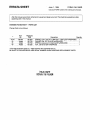 3
3
-
 4
4
-
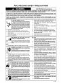 5
5
-
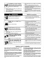 6
6
-
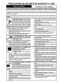 7
7
-
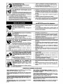 8
8
-
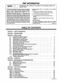 9
9
-
 10
10
-
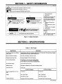 11
11
-
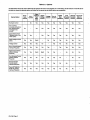 12
12
-
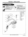 13
13
-
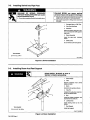 14
14
-
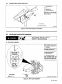 15
15
-
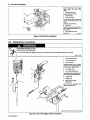 16
16
-
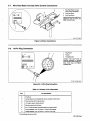 17
17
-
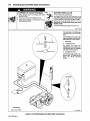 18
18
-
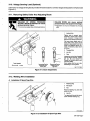 19
19
-
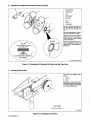 20
20
-
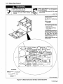 21
21
-
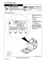 22
22
-
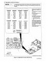 23
23
-
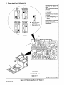 24
24
-
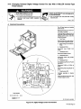 25
25
-
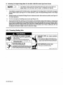 26
26
-
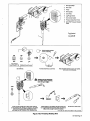 27
27
-
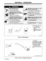 28
28
-
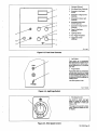 29
29
-
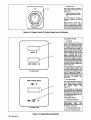 30
30
-
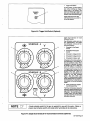 31
31
-
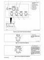 32
32
-
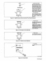 33
33
-
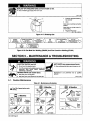 34
34
-
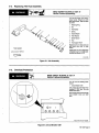 35
35
-
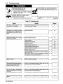 36
36
-
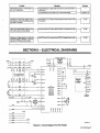 37
37
-
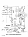 38
38
-
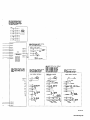 39
39
-
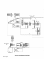 40
40
-
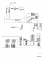 41
41
-
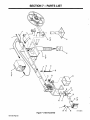 42
42
-
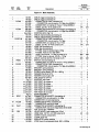 43
43
-
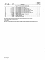 44
44
-
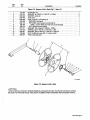 45
45
-
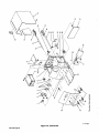 46
46
-
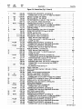 47
47
-
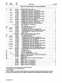 48
48
-
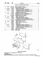 49
49
-
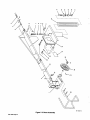 50
50
-
 51
51
-
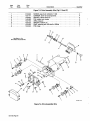 52
52
-
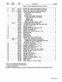 53
53
-
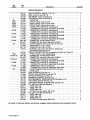 54
54
-
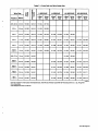 55
55
-
 56
56
-
 57
57
-
 58
58


Miller KE621826 Le manuel du propriétaire
- Catégorie
- Système de soudage
- Taper
- Le manuel du propriétaire
- Ce manuel convient également à
dans d''autres langues
- English: Miller KE621826 Owner's manual
Documents connexes
-
Miller SWINGARC SS-12 AND 16 Le manuel du propriétaire
-
-
-
-
-
-
-
-
-