Enconnex SmartSWING Intelligent Electronic Swing Handle Mode d'emploi
- Catégorie
- Contrôleurs de porte de sécurité
- Taper
- Mode d'emploi

Intelligent Electronic swing handle – User operations
guide
Rev.1.0 1
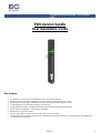
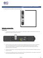
PDU Version handle
User Operations Guide
.
Key Features:
• Local Status monitoring via Integrated Multi-colour LED indicator
• Manual over-ride lock for emergency access (with scalable levels of security)
• Retro-fittable to existing IT cabinets, industry standard 25x150mmpanel cut-out
• Compatible with single and multiple point latching
• Integrated electronics and environmental sensors (temperature and humidity)
• Inbuilt Multi-card reader - 125kHz and 13.56MHz
• External Door contact sensor
• Simple one cable connection for power and communication
• Complete with Centralised Rack Access Management (RAM) Software for configuration, management,
monitoring and reporting

Intelligent Electronic swing handle – User operations
guide
Rev.1.0 2
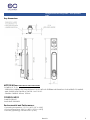
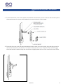
Key dimensions:
MOTOR MODEL ELECTRICAL SPECIFICATION:
-POWER 4.5V TO 5V
- OPERATON CURRENT: LESS THAN 500mA AT 5V DC WITH NO EXTERNAL MECHANICAL LOAD APPLIED TO HANDLE.
- MAX CURENT WITH STALLED ACTUATOR: 1A AT 5V DC.
- STANDBY CURRENT: 300mA, TYPICAL.
CONTROL INPUT:
-RJ485 5V DEVICE
-BAUD RATE:19200 BPS
Environmental and Performance:
> Operating temperature: -15°C to +60°C (5°F to 140°F)
> Survival temperature: -30°C to +85°C (-10°F to +185°F)
> Humidity (operating): 95% RH at 50°C (122°F)

Intelligent Electronic swing handle – User operations
guide
Rev.1.0 3
FCC COMPLIANCE / TM / WARRANTY FCC ID:2AYS5DRLCKHIDP
To satisfy FCC RF exposure requirements, a separation distance of 20cm or more should be maintained between the
antenna of this device and persons during device operation.
To ensure compliance, operations at closer than this distance is not recommended.
Les antennes installées doivent être situées de facon à ce que la population ne puisse
y être exposée à une distance de moin de 20 cm. Installer les antennes de facon à ce
que le personnel ne puisse approcher à 20 cm ou moins de la position centrale de l’
antenne.
This device complies with Part 15 of the FCC Rules
Operation is subject to the following two conditions: (1) this device may not cause harmful interference,
and (2) this device must accept any interference received, including interference that may cause
undesired operation.
Le présent appareil est conforme. L’exploitation est autorisée aux deux conditions suivantes : (1) l’appareil ne doit
pas produirede brouillage, et (2) l’utilisateur de l’appareil doit accepter tout brouillage radioélectrique subi, même
sile brouillage est susceptible d’en compromettre le fonctionnement.
Changes or modifications not expressly approved by the party responsible for compliance could void the
user’s authority to operate the equipment.
This equipment has been tested and found to comply with the limits for a Class B digital device, pursuant
to part 15 of the FCC Rules. These limits are designed to provide reasonable protection against harmful
interference in a residential installation. This equipment generates uses and can radiate radio frequency
energy and, if not installed and used in accordance with the instructions, may cause harmful interference
to radio communications. However, there is no guarantee that interference will not occur in a particular
installation. If this equipment does cause harmful interference to radio or television reception, which can
be determined by turning the equipment off and on, the user is encouraged to try to correct the
interference by one or more of the following measures:
• Reorient or relocate the receiving antenna.
• Increase the separation between the equipment and receiver.
• Connect the equipment into an outlet on a circuit different from that to which the receiver is connected.
• Consult the dealer or an experienced radio/TV technician for help.

Intelligent Electronic swing handle – User operations
guide
Rev.1.0 4
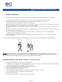
• Safety Instructions
• Please refer to the below instructions before using the Ihandle. Save this manual for future reference.
• ■ If cleaning The Ihandle is required. Don’t use liquid or spray detergent; use a moist cloth.
• ■ Install and operate the Ihandle Preferably, in an air-conditioned environment with
• temperatures not exceeding 50º Celsius (122º Fahrenheit).
• ■ When installing, place the equipment on a sturdy, level surface to prevent it from accidentally falling and
causing damage to other equipment or injury to persons nearby.
• ■ Install the Ihandles Communication and door contact cables in such a way that others won’t trip or fall
over it.
• ■ Keep all liquids away from the equipment to minimize the risk of accidental spillage. Liquid spilled on to
the Ihandle may cause damage.
• ■ Only qualified service personnel should open the chassis. Opening it yourself could damage the
equipment and invalidate the warranty.
• ■ If any part of the equipment becomes damaged or stops functioning, have it checked by qualified
service personnel
Take care when the swing handle is in the open position, to avoid personal injury or damage to the swing handle body.
DO NOT use excessive force to open the swing handle and always fully open the swinghandle by gently opening in an
upwards position. Once fully in the upwards position turn the handle either left or right based on the position of the rotation
limiter. Failure to operate the handle correctly can lead to damage to the handle body.
Standard warranty 2 years repair or replace. See exclusions below
• Damage, deterioration or malfunction resulting from:
• Accident, misuse, neglect, fire, water, lightning, or other acts of nature, unauthorized product modification,
or failure to follow instructions supplied with the product.
• Repair or attempted repair by anyone not authorized persons.
• Any damage of the product due to shipment.
• Removal or installation of the product.
• Causes external to the product, such as electric power fluctuations or failure.
• Use of third-party parts not meeting our specifications.
• Normal wear and tear.
• Any other causes which do not relate to a product defect.

Intelligent Electronic swing handle – User operations
guide
Rev.1.0 5
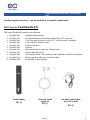
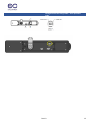
Standard supplied Inventory * can be modified to suit specific requirements
PDU Version Smart-Handle Kit:
The Smart-Handle Kit comprises the following:
• Quantity 1pcs Intelligent swing handle
• Quantity 1pcs 2m communications cable female rj45 to 4pin JST connector
• Quantity 1pcs 1.2m Door switch sensors to 5 pin JST connector with 2 magnets
• Quantity 1pcs 2.5m Cat6 Blue network cable
• Quantity 2pcs Double sided tape
• Quantity 5pcs Cable tie
• Quantity 1pcs Metal bracket back cover and 3 fixing screw
• Quantity 1pcs Cable protection covers
• Quantity 1pcs Thin rotation limiter * thick rotation limiter installed on ihandle as standard
• Quantity 1pcs Spring screws to affix cam to rotation limiter
• Quantity 2pcs Euro profile lock barrel keys
1.2m door switch
sensor kit
QTY (1)
Smart Handle
QTY (1)
2m daisy chain Cable
4 pin JST to RJ45
QTY (1)

Intelligent Electronic swing handle – User operations
guide
Rev.1.0 6
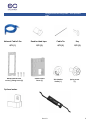
Optional extras.
Metal bracket back
cover (1) fixing screw (3)
Cable Protect
Cover (1)
Thin Rotation
limiter (1)
Spring screw
(1)
Double-sided tape
QTY (2)
Network Cable 2.5m
QTY (1)
Cable Tie
QTY (5)
Key
QTY (2)

Intelligent Electronic swing handle – User operations
guide
Rev.1.0 7
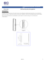
Door cams Multi latching rod system gearbox
Installation:
Check the cut-out dimensions. For retrofit, remove the existing rack handles and check the cut-out dimensions
(see picture below for typical front door and rear door). Keep the cam from the existing handles (used in Step 4).
Note: The Smart-Handle can be retrofitted on racks subject to the door having a cut-out dimensions
125mmx50mm.

Intelligent Electronic swing handle – User operations
guide
Rev.1.0 8
1.
Typical door Typical door
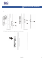
2. Push the Smart-Handle through the cut-out in the door.

Intelligent Electronic swing handle – User operations
guide
Rev.1.0 9
3. Put the metal back cover on the inside of the handle and insert the 3 screws to secure the handle in place,
alternate between the screws while tightening to prevent skewing of the handle.
4. Place the door cam over the handle spindle and then a thick or thin door limiter using the spring screw to
secure the mechanism. (For retrofit, re-use the front and rear door cam). Check the cam closes snuggly
when the handle is rotated. Swap the door limiters or slightly bend the cam if the cam hits the rack frame.

Intelligent Electronic swing handle – User operations
guide
Rev.1.0 10
5. Repeat the procedure for the second door.
Network connection:
Front Door
1. Connect the Smart-handle Comms Cable 4 pin to RJ45 150mm cable to the iHandle and attach the
Blue Network Cable to the RJ45 connector.
2. Connect the RJ45 coupler and Blue Network Extension Cable to the Blue Network Cable.
3. Route and fix the network cable using cable ties and adhesive pads. Ensure the network cable has
slack on the hinge side of the door so that it does not get pinched. Ensure the RJ45 coupler is
positioned near the hinge to enable the network cable to be disconnected and allow the easy
removal of the door (if required).
4. Install the Cable Protect Cover by placing it over the back of the Smart-handle and sliding the Cable
Protect Cover up.
5. Connect the blue Network cable to the RJ45 Sensor Port on either the IPDU, in-line meter or sensor POD.
The Smart-handle LED light should now be illuminated.

Intelligent Electronic swing handle – User operations
guide
Rev.1.0 11
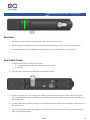
Rear Door
1. The network connection for the rear door is the same as the front door.
2. Ensure the network cable has slack on the hinge side of the door so that it does not get pinched.
3. Connect the RED Network cable to the RJ45 Sensor Port on either the IPDU or sensor POD
Door Switch Sensor
1. The Door Switch Sensor consists of two parts:
● 1.2m cable to 5pin connector with Door switch sensor
● Magnet
2. Plug the 5pin connector into the back of the Smart-handle.
3. Route and attach the 1.2m cable to the inside of the door and attach the switch sensor to the door
using a dual adhesive pad or screws. In most instances the best location is near the top of the door on
the handle side.
4. Close the door and locate the position on the frame inside the rack that corresponds to the location of
the switch sensor.
5. Open the door and attach the Magnet to the frame in the location identified using a dual adhesive
pad or M3 tapping screws.

Intelligent Electronic swing handle – User operations
guide
Rev.1.0 12
6. The magnet and switch sensor must come into contact when the door is closed for the sensor to
determine door closed status.
Lock:
1. The Euro profile lock barrel can be replaced with an alternate lock barrel either before or after the
handle is installed.
2. Removing the lock retaining screw.
3. Slide the lock cylinder barrel out of the Smart-handle and replace it with the alternate barrel.
4. Re-install the lock retaining screw.
Note: The lock barrels supplied by Logical Infrastructure are designed specifically for use with the Smart-
handle. Other lock barrels may result in reduced Smart-handle functionality.
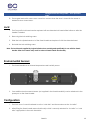
Environmental Sensors:
1. The Smart-handle has an internal temperature and humidity sensor.
2. One additional environmental sensor (not supplied in the Smart-handle kit) can be attached to the
spare port on the Smart-handle.
Configuration:
1. The front door of a rack is referred to as the “cold aisle” and the rear door as the “hot aisle”.
2. After fitting the Smart-handle ensure that the dip switch is correctly selected for “hot aisle” or “cold
aisle” appropriate to the rack orientation.

Intelligent Electronic swing handle – User operations
guide
Rev.1.0 13

Intelligent Electronic swing handle – User operations
guide
Rev.1.0 14
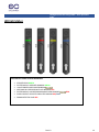
LED light status:
LATCH & LED colour STATUS definitions
• SECURED SOLID GREEN
• ELECTRONICALLY RELEASED BLINKING GREEN
• UNAUTHORISED CARD SWIPE BLINKING
• MECHANICALLY RELEASED WITH KEY BLINKING RED
• ELECTRONICALLY LOCKED/SWINGHANDLE OPEN BLINKING /RED
• DOOR CONTACT OPEN FOR 5 MINUTES BLINKING RED/BLUE
• ERROR DETECTED SOLID RED

Intelligent Electronic swing handle – User operations
guide
Rev.1.0 15
Operate with PDU:
1.Setup:
The Smart-handle can be connected to PDU before or after PDU power up, it usually take 10 to 50 seconds for
the Smart-handle detected by PDU, once the Smart-handle detected, the sensor handle, keyed lock and
relevant information can be found from PDU’s local display, web GUI or snmp interface.
Local Display: Select menu item sensor, use scroll button to view all connected sensors
SNMP – refer to PDU snmp description
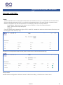
Web GUI:
Once the Smart-handle detected, login to PDU’s web GUI, handle lock and door switch status will be shown at
home page under “Security” tag:
Handle built-in temperature and humidity sensor will be shown under Environmental tag
Setup handle:
Handle related configuration interface can be invoked from setting -> Rack Access Control menu

Intelligent Electronic swing handle – User operations
guide
Rev.1.0 16
Rack Access Control page allows PDU user to perform following configuration:
o Authorize an rf id card user
o Lock/Unlock the handle
o Change the auto lock time
o All above configure are under the Action Button as following
Authorize rf id card user
An ID card user need to be defined given card ID and user name. The card ID is the property of a HID card
or Mifare card, which is different as the number printed on the card in most of the cases, to get the card
ID, present the card in front of the read area on the handle, the handle led will blink orange, and then

Intelligent Electronic swing handle – User operations
guide
Rev.1.0 17
check the event log of the PDU(it takes about 30 seconds for the PDU to pull the latest event from Handle),
the log should include item like following:
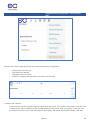
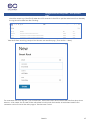
Take the ID from event log, and put into the new user creation pag ( From Action -> New)
The username can be in any test – just for memories , select the correct PDU number and Aisle from drop-down
selector, click create, the ID card will be authorized to lock/unlock the handle, all authorized card ID and
username can be found at the main page of Rack Access Control

Intelligent Electronic swing handle – User operations
guide
Rev.1.0 18
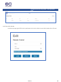
Lock/Unlock the handle
Lock/Unlock page gives PDU user to performan lock unlock without access the handle with a ID card

Intelligent Electronic swing handle – User operations
guide
Rev.1.0 19
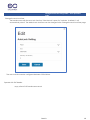
Change the auto lock time
The handle come with the auto lock function, if the the lock is open for 3 minutes in default, it will
automatically close it. The default auto lock time can be changed in the Change the auto lock time page
The auto lock time can be configured between 3-30 minitues.
Operate with PoE Handle
Please refer to PoE handle user manual

Intelligent Electronic swing handle – User operations
guide
Rev.1.0 20
FAQ:
• What if the smart-Handle fails how do I access my IT cabinet? Use the override key provide to manually
open the swing handle.
• Does the smart-Handle fail safe if power is lost or the communications cable is disconnected? Yes, the
smart-Handle will stay in the locked position and when powered up again will automatically check that
latch is in the locker position
• Is the smart-Handle self-latching? Yes, as long as the key barrel is in the 12 o’clock lock position and the
electronic latch in the lock position once the swinghandle is closed, the latch will allow the key cam to
push up the latch and the spring action will drive the latch back down.
• Can I use my own Euro profile lock barrel? Yes, if the barrel is a standard Euro profile.
• My current multi point rode systems gear box does not fit the smart-Handle where can I get a gearbox that
works with my multi point rod system? We can design a compatible gearbox as an optional extra. Please
contact with our sales.
• I’m trying to use my internal companies swipe card and it isn’t working why? Your companies swipe cards
may be encrypted to your building management system card readers. The smart-Handle requires an open
sector on your card in order to read the CSN number.
• I’ve connected my smart-Handle to my building management system but it’s not working why? The smart-
Handle uses the RS485 protocol and only approved vendor hardware is supported by our Firmware. Please
contact with our sales to discuss your requirements.
• I’ve lost some parts, can I buy spares. Yes, please contact with our sales and we will get in contact with
you regarding your requirement.
• Can you integrate with third party access control systems? Yes and No it depends on the communication
protocol being used by the third-party system and whether the third party vendor is open to integrating the
smart-Handle into their system, please contact with our sales to discuss in more detail.
• How accurate is the supplied temperature and humidity sensor? The sensors are accurate up to 2 degrees
and 5% humidity and have been calibrated to react slowly to changes to avoid large swings in
temperature and humidity when the door is opened and closed for short periods of time. This setup is
designed to give the user stable readings and avoid unnecessary threshold alarms.
Trouble shooting:
• The LED light on my smart-Handle has not turned on. Make sure the communications cable is plugged into
the correct port on the smart-Handle.
• My smart-Handle has a flashing blue/red LED. Make sure the supplied door switch sensor is connected to
the smart-Handle and that the magnet has been installed correctly.
• The aisle setting on my smart-Handle is not correct and I’ve switched it into the correct position, but the
aisle detail has not changed. Power down the smart-Handle by disconnecting the communications cable
make sure the dip switch is in the desired position and re-power up the smart-Handle and allow the smart-
Handle to reboot and sync, this should resolve the issue.
-
 1
1
-
 2
2
-
 3
3
-
 4
4
-
 5
5
-
 6
6
-
 7
7
-
 8
8
-
 9
9
-
 10
10
-
 11
11
-
 12
12
-
 13
13
-
 14
14
-
 15
15
-
 16
16
-
 17
17
-
 18
18
-
 19
19
-
 20
20


Enconnex SmartSWING Intelligent Electronic Swing Handle Mode d'emploi
- Catégorie
- Contrôleurs de porte de sécurité
- Taper
- Mode d'emploi
dans d''autres langues
Autres documents
-
Eaton 9395C-1100/1100 Mode d'emploi
-
Alpha XM3.1-HP Broadband UPS Technical Manual
-
 Nice HySecurity SlideSmart CNX Slide Gate Operator Guide d'installation
-
Oracle Exadata Storage Server X7-2 HC Guide d'installation
-
LG DLEX7900BE Le manuel du propriétaire
-
-
Lanner NCA-6040 Manuel utilisateur
-
LG LRFDS3006D Manuel utilisateur
-
LG DLEX5780WE Le manuel du propriétaire
-
HySecurity SlideDriver II Mode d'emploi
