Lifetime 90599 Le manuel du propriétaire
- Taper
- Le manuel du propriétaire

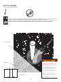
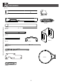
TOOLS REQUIRED TABLE OF CONTENTS
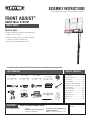
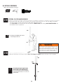
• Requires at least 493 lb (224 kg) of cement mix to fi ll a
volume of 3.7 ft3 (0,105 m3).
• Requires, at least, 3 days for concrete to cure, plus
3–4 hours to complete assembly steps.
• At least 2 people recommended for setup.
Pour le français, voir la page 2. Para el español, ver la página 3.
ASSEMBLY INSTRUCTIONS
MODEL 90599
Save this instruction in the event that the manufacturer must be contacted for replacement parts.
BEFORE ASSEMBLY:
CONTACT LIFETIME CUSTOMER SERVICE:
Dial 1-800-225-3865
QUESTIONS? Model Number: 90599
Product ID:
For Customer Service in Mainland Europe
and the United Kingdom,
E-mail: [email protected]
Live Chat:
www.lifetime.com/customerservice/home
(Click on the "LIVE CHAT" tab)
7/16" (≈11 mm)
(x2)
(x1)
(x1) (x1)
1/2" (≈13 mm)
(x2)
(x1)
9/16" (≈14 mm)
(x2)
3/4" (≈19 mm)
(x2)
(x1)
(x1)
Concrete Mix
493 lb (224 kg)
(x1)
(x1)
(x1)
Icon Legend...............................2
Warnings & Notices.....................3
Initial Setup...............................4
Pole Assembly..........................10
Backboard-to-Rim Assembly......14
Backboard-to-Pole Assembly......18
Parts Identifi er.........................i–iv
Handle Assembly......................23
Final Assembly.........................30
Maintenance............................35
Warning Sticker........................36
Registration........................38
Warranty................................39
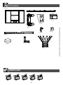
FRONT ADJUST®
BASKETBALL SYSTEM
(x1)
Bricks (x8–10)

2
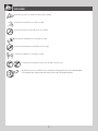
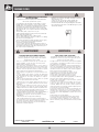
• Indicates the parts to be used for a section.
• Indicates special heed should be taken when reading.
• Indicates the hardware to be used for a section.
• Indicates the tools to be used for a section.
• Indicates no hardware required for a specifi c page.
• Indicates no parts required for a specifi c section.
• Indicates to use/not to use an electric drill for a specifi c step.
ICON LEGEND
• Indicates the use of a centerlock nut. A nut with this marking will require some effort to tighten.
This hardware was designed with this feature in order to prevent loosening later.

33
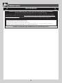
WARNINGS & NOTICES
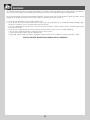
Most injuries are caused by misuse and/or not following instructions. Use caution when using this product.
To ensure safety, do not attempt to assemble this product without following the instructions carefully. Check entire box and inside all packing
material for parts and/or additional instruction material. Before beginning assembly, read the instructions and identify parts using the hardware
identifi er and parts list in this document. Proper and complete assembly, use and supervision are essential for proper operation and to reduce the
risk of accident or injury. A high probability of serious injury exists if this product is not installed, maintained, and operated properly.
FAILURE TO FOLLOW THESE WARNINGS MAY RESULT IN SERIOUS INJURY OR PROPERTY DAMAGE AND WILL VOID WARRANTY.
Owner must ensure that all players know and follow these rules for safe operation of the system.
• If using a ladder during assembly, use extreme caution.
• Two capable adults are recommended for this operation.
• Check base daily for leakage. Leaks will cause system to fall.
• Assemble the pole sections properly. Failure to do so could cause the pole sections to separate during play or transport.
• Minimum operational height is 6 ft 6 in (1.98m) to the bottom of the backboard.
SAFETY INSTRUCTIONS

4
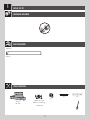
INITIAL SET UP
1
ALE (x1)
(x1)
(x1)
(x1)
(x1)
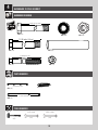
HARDWARE REQUIRED
PARTS REQUIRED
TOOLS REQUIRED
Metal Parts
Concrete mix
60-lb bags (≈x9)
(493 lb) (≈223,6 kg)
Bricks
(x8–10)

5
SECTION 1 (CONTINUED)
TOOLS AND HARDWARE REQUIRED
1
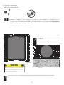
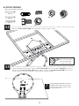
• IMPORTANT! Dig a round hole 24" (≈61 cm) deep and 18" (≈45.7 cm) in diameter. If you live in an area where frost heaves
may pose a problem, consult your local building inspector to determine the proper hole depth. The edge of the hole
should be fl ush with the edge of the playing surface.
!• A ground sleeve is available as an alternative to cementing the pole into the ground. Please contact Customer Service for more information.
• The edge of the 18" (≈45.7 cm) diameter hole should touch the edge of
the playing surface.
(x1)
(x1)
1.1
• Before digging, call to locate any buried utility lines.
• Avant de creuser, appelez pour localiser des utilités
publiques entérrées.
• Antes de cavar, llame para localizar las conexiones
de servicios públicos subterráneas.
CAUTION
! !
!
Playing Surface
Top view
24" (≈61 cm)
18" (≈45,7 cm)
Side view

6
SECTION 1 (CONTINUED)
TOOLS AND HARDWARE REQUIRED
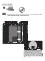
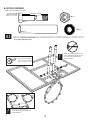
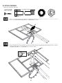
• Stack bricks or patio blocks in the hole so the top of the stack measures 9.5" (≈24,1 cm) from the bottom of the hole (Fig.
1). The edge of the bricks should be about 2 1/2" (≈7 cm) from the playing surface (Fig. 2).
Fig. 1
Fig. 2
1.2
Playing Surface
24" (≈61cm)
18" (≈45,7 cm)
14.5"
(≈36,8 cm)
9.5"
(≈24,1 cm)
Side view
Top view
(x1)
2 1/2" (≈7 cm)
Bricks (x8–10)

7
SECTION 1 (CONTINUED)
TOOLS AND HARDWARE REQUIRED
1.2
(x1)
(x1)
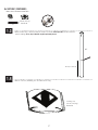
• Make a mark 14.5" (≈36.8 cm) from the dimpled end of the bottom pole (ALE) (do not scratch the
powder coating). Please, keep in mind this step when performing the next.
14.5 in/po (≈36.8 cm)
ALE
1.3
1.4
Concrete mix
420 lb (191 kg)
• Mix the concrete, following the directions on the bag.
Concrete mix
60-lb bag (≈x9)
(493 lb (≈223,6 kg))

8
SECTION 1 (CONTINUED)
TOOLS AND HARDWARE REQUIRED
1.5
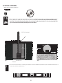
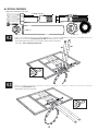
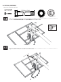
!• Use a level to ensure the bottom pole is standing vertical. Form the cement into a downward slope away from the pole to allow water runoff. Failure to do
so may result in premature rusting of the pole.
(x1)
21" (≈53,3 cm)
18" (≈45,7 cm)
14.5"
(≈36,8 cm)
9.5"
(≈24,1 cm)
Side view
• 14.5" (≈36.8 cm) mark
18" (≈46 cm)
4" (≈10,2 cm)
Playing Surface
Fig. 1 Fig. 2
• Set the bottom of the bottom pole onto the bricks or patio blocks. The 14.5" (≈36.8 cm) mark on the pole should be fl ush with the playing
surface (Fig. 1). If it is not fl ush, the system will not adjust to the correct heights. The edge of the pole should be 4" (≈10.2 cm) from the playing surface
(Fig. 2) to ensure the back board overhangs the playing surface. If it is not, adjust it.
(x1)

9
SECTION 1 (CONTINUED)
TOOLS AND HARDWARE REQUIRED
• The slots at the top of the bottom pole must be parallel to the playing surface. Turn the pole, if necessary. Pour the mixed
concrete into the hole until it is fi lled to the level of the playing surface and the 14.5" (≈36,8 cm) mark on the pole.
Form the concrete into a downward slope away from the pole to allow for runoff. Allow the concrete to cure for 72 hours.
1.6
14.5" (≈36,8 cm) mark
Downward slope
Playing surface • Stop assembly now. Do not continue the assembly
until the concrete has been allowed to set for at
least 72 hours (3 days). In humid climates or wet
weather, allow more time for the concrete to cure.
Do not proceed until the curing process is complete.
!
!
• Ne pas continuer l’assemblage jusqu’à ce que le
béton ait été permis durcir, au moins, 72 heures
(3 jours). Sous les climats humides, laisser plus de
temps pour que le béton durcisse. Ne pas continuer
jusqu’à ce que le durcissement soit complète.
• Pausar el ensamblaje ahora. No continuar
el ensamblaje hasta que el concreto haya sido
permitido curar, por lo menos, 72 horas (3 días).
En climas húmedos, dejar más tiempo a que
el concreto se cure. No continuar hasta que el
endurecimiento se termine.
WARNING / AVERTISSEMENT
ADVERTENCIA
(x1)

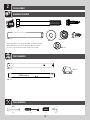
10
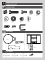
POLE ASSEMBLY
2
BCO
Metal Part
Hardware Bag
TOOLS REQUIRED
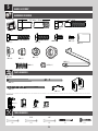
PARTS REQUIRED
HARDWARE REQUIRED
(2) (1)
9/16”
ADS (x2)*
ABZ (x2)*
ABB (x2)
AAF (x2)
ABE (x2)
ABR (x2) CIH (x2)*
*Note: Only one #14 x 1” Self-Tapping Screw (ABZ), one Domed Countersink
Washer (CIH) and one 1/4” x 3/4” Pan Head Screw (ADS) will be used for
this section. Save the remaining hardware for later in the assembly.
Scrap Wood
ALH (x1)
ALF (x1)
Warning Sticker
ALL (x1)
(1) (1)

11
TOOLS AND HARDWARE REQUIRED
SECTION 2 (CONTINUED)
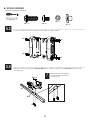
2.1 • Insert the 3/8” x 4” Hex Bolts (ABE) with the 3/8” Washers (AAF) into the Middle Pole (ALF) as shown. Then slide the 1/2” x
3.41” Spacers (ABR) onto the Hex Bolts.
ALF
ABE
ABR
Warning
Sticker
AAF
Large Holes
Small Holes
AAF (x2)
ABE (x2)
ABR (x2)

12
TOOLS AND HARDWARE REQUIRED
SECTION 2 (CONTINUED)
2.2 • Place the Pole Bracket (ALL) onto the 3/8” x 4” Hex
Bolts (ABE), and attach it to the Middle Pole (ALF)
with the hardware shown.
• The 1/4” x 3/4” Screw should be fl ush with the Pole,
but will spin freely once installed. Do not jam the Poles
together until instructed.
!
9/16" (x2)
2.3 • Align the hole in the Top Pole (ALH) with the slot in
the Middle Pole (ALF) and slide the Top Pole over the
Middle Pole. Insert a 1/4” x 3/4” Screw (ADS) through
a Domed Countersink Washer (CIH), into the small hole
in the Top Pole, and into the slot in the Middle
Pole as shown. The Screw head should fi t into the
Countersink Washer.
ALF
ABB
ALL
ABE
ABB (x2) ADS (x1)
ALH
ALF
ALH
ALF
ADS
CIH
CIH (x1)

13
TOOLS AND HARDWARE REQUIRED
SECTION 2 (CONTINUED)
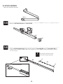
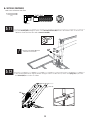
• After the Poles have been seated, insert a #14 x 1”Self-Tapping Screw (ABZ) into the back of the Pole as shown.
2.5
2.4 • In order to seat the Poles, strike each end of the Pole very hard fi ve to six times on a piece of scrap wood or cardboard.
This must be done even if the Poles cover the slots before seating has occurred.
If the Top Pole (ALH) does not completely cover the slots on the Middle Pole (ALF) after seating, DO NOT COMPLETE ASSEMBLY. Call
our Customer Service Department.
WARNING
The poles must be seated together! Even if the poles cover
the slots before seating, they must be struck on a hard
surface fi ve to six times! Failure to seat the poles correctly
could allow the poles to separate during use, which could
lead to serious personal injuries or property damage.
Wood Block
ATTENTION: THIS STEP CANNOT BE REVERSED!
ALH
ALF
ALH
ALF
ABZ
ABZ (x1)
• Do not hit your feet with the Pole sections,
as serious injury could occur.
!
• THE SCREWS (ABZ) ARE DESIGNED TO DRILL
INTO THE METAL OF THE UNDERLYING POLE.
For ease of installation, chuck the Self-Drilling
Screws directly into the drill, or use a 3/8 in. (10
mm) Hex Driver.
!

14
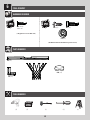
BACKBOARD-TO-RIM ASSEMBLY
3
BCS
Metal Parts
Hardware Bag
PARTS REQUIRED
HARDWARE REQUIRED
ABD (x2)
5/16”
ABF (x2)
7/16”
AAM (x2)
ABK (x4)
5/16”
AJW (x2) APZ (x1)
AOW (x1)
AAV (x2)
DFE (x4)
AAA (x4)
AAJ (x2)
AJI (x1)
ALX (x1)
ALD (x1)
DFD (x1)
AMY (x2)
Plastic Parts
TOOLS REQUIRED
(2) (2) (2)
1/2” 7/16” 9/16”

15
TOOLS AND HARDWARE REQUIRED
SECTION 3 (CONTINUED)
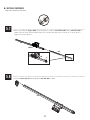
3.1 • Insert two Bolts (AAM) with Washers (ABD) and Rubber Washers (ABF) through the holes indicated in the back of the Rim (ALX) as
shown. Secure the hardware with two T-Nuts (AAJ).
1/2" (13 mm)
ABD (x2) ABF (x2)
AAM (x2)
AAJ (x2)
(x2)
(x1)
• Ensure that the tap bolts (AAM) are positioned on
the outside edge of the holes as shown.
• Do not overtighten the hardware so much that the
rubber washers bulge as shown.
!
!
AAJ
AAM
ABD
ABF
ALX
ABF ABF
AAJ
AAM
ABD
ABF

16
TOOLS AND HARDWARE REQUIRED
SECTION 3 (CONTINUED)
1/2” (x2)
3.2 • Connect the Rim (ALX) and Plastic Guard (ALD) to the Backboard (AJI) with the hardware shown. Secure the 5/16” Nylock Flange
Nuts (ABK) onto the Tap Bolts (AAM).
ABK (x2)
APZ (x1)
APZ
ALX
ABK
ALD
AAM
AJI
DFD

17
TOOLS AND HARDWARE REQUIRED
SECTION 3 (CONTINUED)
AAV
ABK
AOW
AJW
APZ
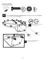
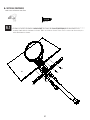
3.3
• Turn the Backboard Assemly over. Thread the 5/16” Jam Nuts (AAV) onto each end of the U-Bolt (APZ) as far as they
will go. Slide the Compression Springs (AJW) onto the U-Bolt, and place the Spring Retainer Plate (AOW) over the Com-
pression Springs. Secure the Plate to the Springs with the hardware shown.
• Attach the Backboard Brackets (AMY) to the Backboard using the hardware shown.
AAV (x2) ABK (x2)
AJW (x2)
AOW (x1)
1/2”(x2)
7/16”(x2)
9/16”(x2)
• DO NOT COMPLETELY TIGHTEN THE 5/16” NYLOCK
FLANGE NUTS IN THIS STEP! Only tighten the Nuts
until the Rim does not wobble. Tightening the Nuts
will adjust the Rim tension.
!
DFE (x4) AAA (x4)
AAA
DFE
DFE
DFE
DFE
AAA
AMY
• A Centerlock Nut
will require some effort
to thread onto a Bolt.
See page 2 for details.
3.4

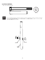
18
7 5/8 in/po (≈19cm)
Metal Parts
Hardware Bag
TOOLS REQUIRED
PARTS REQUIRED
HARDWARE REQUIRED
4
(x2) (x2)
3/4" (≈19 mm) 9/16" (≈14 mm)
(x1)
BCR
AJY (x2)
AKC (x2)
AKB (x2)
AAX (x4)
ABB (x1)
AAD (x2)
GBU (x2)
DFC (x1)
7 1/16 in/po (≈18cm)
7 1/2 in/po (≈19cm)
7 1/2”
DGA (x2)
ABN (x8)
7 5/8 in/po (19.4 cm)
7 1/2 in (19 cm)
30 1/6 in (76.4 cm)
7 1/2 in/po (19 cm)
21 1/8 in (53.6 cm)
BACKBOARD-TO-POLE ASSEMBLY

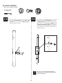
19
SECTION 4 (CONTINUED)
TOOLS AND HARDWARE REQUIRED
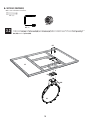
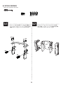
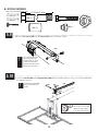
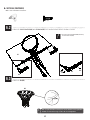
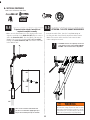
4.1 • Attach the Short Extension Arms (AKC) to the Backboard Brackets in the location shown with the hardware indicated.
Secure only by hand at this point.
AKC
AKC
AAX ABN
ABN
DGA
AAX (x1)
ABN (x2)
DGA (x1)
3/4" (≈19 mm) (x2)
• DO NOT strike this Bolt (GBU) with a mallet!
If there is diffi culty sliding the Bolt into place,
use a wrench to turn the Bolt until it has
advanced into position.
!
• A Centerlock Nut requires
some effort to thread onto a
Bolt. See page 4 for details.
• If necessary, use a bolt to remove any
excess powder coating from the holes in the
Backboard Brackets.
!
GBU (x1)
GBU
7 5/8 in/po (≈19cm)

20
SECTION 4 (CONTINUED)
TOOLS AND HARDWARE REQUIRED
AKB AKB
AAX
ABB
DFC
DGA
GBU
AAX (x1)
DGA (x1)
9/16" (≈14 mm) (x2)
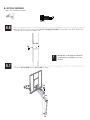
4.2 • Attach the ends of the Long Extension Arms (AKB) (that only have one hole)
to the Backboard Brackets in the location shown with the hardware
indicated. Secure only by hand at this point.
• Secure the Hex Bolt (DFC) to the
Backboard Brackets as shown.
4.3
ABB (x1)
DFC (x1)
7 1/2 in/po (≈19cm)
7 1/2”
7 1/2 in/po (19 cm)
3/4" (≈19 mm) (x2)
ABN (x2)
ABN
ABN
GBU (x1)
7 5/8 in/po (≈19cm)
7 5/8 in/po (19.4 cm)
La page charge ...
La page charge ...
La page charge ...
La page charge ...
La page charge ...
La page charge ...
La page charge ...
La page charge ...
La page charge ...
La page charge ...
La page charge ...
La page charge ...
La page charge ...
La page charge ...
La page charge ...
La page charge ...
La page charge ...
La page charge ...
La page charge ...
La page charge ...
La page charge ...
La page charge ...
La page charge ...
La page charge ...
-
 1
1
-
 2
2
-
 3
3
-
 4
4
-
 5
5
-
 6
6
-
 7
7
-
 8
8
-
 9
9
-
 10
10
-
 11
11
-
 12
12
-
 13
13
-
 14
14
-
 15
15
-
 16
16
-
 17
17
-
 18
18
-
 19
19
-
 20
20
-
 21
21
-
 22
22
-
 23
23
-
 24
24
-
 25
25
-
 26
26
-
 27
27
-
 28
28
-
 29
29
-
 30
30
-
 31
31
-
 32
32
-
 33
33
-
 34
34
-
 35
35
-
 36
36
-
 37
37
-
 38
38
-
 39
39
-
 40
40
-
 41
41
-
 42
42
-
 43
43
-
 44
44


Lifetime 90599 Le manuel du propriétaire
- Taper
- Le manuel du propriétaire
dans d''autres langues
- English: Lifetime 90599 Owner's manual
- español: Lifetime 90599 El manual del propietario
Documents connexes
-
Lifetime 1558 Le manuel du propriétaire
-
-
-
-
-
-
-