Fisher & Paykel OR30SCI6B1 Guide d'installation
- Catégorie
- Cuisinières
- Taper
- Guide d'installation

OR0SDI & OR0SCI Induction
& OR0SDE Glass Ceramic
models
FREESTANDING COOKER
INSTALLATION GUIDE
US CA
591507D 10.19

2
CONTENTS
Safety and warnings 3
Parts supplied for installation 5
Tools needed for installation (not supplied with the appliance) 5
Model identification 6
Prior to installation 6
Product dimensions 7
Clearance dimensions 8
Fitting the optional backguard 9
Location of electrical supply 9
Ventilation requirements 10
Fitting the adjustable feet 11
Moving the range 12
Installing the anti-tip bracket 13
Electrical connection 15
Final checklist 17

3
SAFETY AND WARNINGS
IMPORTANT SAFETY INSTRUCTIONS!
Save these instructions for the local inspectors use.
To avoid hazard, follow these instructions carefully before installing or using this
appliance.
Please make this information available to the person installing the appliance – doing so
could reduce your installation costs.
This range is to be installed and connected to the electricity supply only by an authorized
person.
If the installation requires alterations to the domestic electrical system, call a qualified
electrician. The electrician should also check that the socket cable section is suitable for
the electricity drawn by the range.
Service should only be done by authorized technicians. Technicians must disconnect the
power supply before servicing this appliance.
The range must be grounded.
Installation must comply with your local building and electricity regulations.
This appliance must be installed and connected to the mains power supply only by a
suitably qualified person according to these installation instructions and in compliance
with any applicable local building and electricity regulations.
The manufacturer accepts no responsibility for the incorrect installation of appliances.
Incorrect installation may result in personal injury, damage to property and may
invalidate any warranty or liability claims
Do not modify this appliance.
Do not use or store flammable materials on or near this appliance
If the power supply cable is damaged, it must be replaced by the manufacturer, its
service agent or similarly qualified person in order to avoid a hazard.
A circuit breaker is recommended.
Do not use adaptors, reducers or branching devices to connect the oven to the mains
electricity supply, as they can cause overheating and burning.
Improper installation, adjustment alteration, service or maintenance can cause property
damage, injury or death. Read the installation, operating and maintenance instructions
thoroughly before using, installing or servicing this appliance.
The appliance must not be installed behind a decorative door in order to avoid
overheating.
WARNING!
Cut Hazard
Take care – some edges are sharp.
Failure to use caution could result in injury or cuts.
WARNING!
Electrical shock hazard
Before carrying out any work on the electrical section of the appliance,
it must be disconnected from the mains electricity supply.
Connection to a good ground wiring system is absolutely essential
and mandatory.
Alterations to the domestic wiring system must only be made by a
qualified electrician
Failure to follow this advice may result in electrical shock or death.
Installation
WARNING!
1411595
Montagner M.
29/11/2017
.
1:1
.
CODICE
N° DISEGNO
DATA
SCALA
DISEGNATO
CONTROLLATO
IN DATA
SOSTITUISCE IL
DESCRIZIONE:
ETICHETTA STAFFA ANTI-RIBALTAMENTO PER USA/CAN, NOTE PER
INSTALLATORE (RANGE STABILITY MARKING FOR USA/CAN, WARNING FOR THE INSTALLER)
TRATTAMENTO :
MATERIALE :
VEDI NOTE / SEE NOTES
RAGGI NON QUOTATI (mm)
SPESSORI NON QUOTATI (mm)
TOLLERANZE GENERALI
XXX = QUOTE DA CONTROLLARE DURANTE LA PRODUZIONE
E PRIVE DI OGNI DIFETTO
SUPERFICI IN VISTA
N°
MODIFICHE
DATA
FIRMA
1 . .
.
TELEFAX 0423/912360
TEL. 0423/9121
31030 - BORSO del GRAPPA (Italy)
Fisher & Paykel appliances si riserva,
a termini di legge, la proprietá del
presente disegno con divieto di, senza
autorizzazione, riprodurlo o comunicarlo.
NOTE (NOTES):
- MATERIALE E FINITURA (FACESTOCK): POLIESTERE - ARGENTO MATTATO (MATTE SILVER POLYESTER)
- COLORE DI STAMPA (PRINTING COLOUR): NERO/GRIGIO (BLACK/GREY)
- ETICHETTA TIPO “CLASS IIIA-1”, ETICHETTA PERMANENTE (”CLASS IIIA-1” PERMANENT LABEL)
- IL PRODOTTO DEVE RESISTERE AD AGGRESSIVI CHIMICI E SOLVENTI (THE PRODUCT MUST BE RESIST
TO CHEMICALS AND SOLVENTS)
- L’ETICHETTA DEVE ESSERE ATTACCATA SULLA LAMIERA POSTERIORE DELLA CUCINA. BISOGNA
PRESTARE ATTENZIONE A NON OSTRUIRE LE APERTURE DI VENTILAZIONE (THE LABEL SHALL BE
ATTACHED ON THE COOKER REAR PANEL. CARE MUST BE TAKEN NOT TO OBSTRUCT THE
VENTILATION OPENINGS)
Cod. 1411595
WARNING - AVERTISSEMENT
A child or adult can tip the range and be killed (Une personne,
enfant ou adulte, peut faire basculer la cuisinière et subir des
blessures mortelles).
Install anti-tip device to range and/or structure per installation
instructions (Installer le dispositif antibasculement sur la cuisinière
et/ou la structure, conformément aux instructions d’installation).
Engage the range to the anti-tip device installed to the structure
(Engager la cuisinière dans le dispositif antibasculement installé sur
la structure).
Re-engage anti-tip device if range is moved (Engager le dispositif
antibasculement de nouveau si la cuisinière a été déplacée).
Failure to follow these instructions can result in death or serious
burns to children and adults (Le non-respect de ces directives
expose enfants et adultes à un risque de décès ou de brûlures graves).
To verify the anti-tip bracket is installed and engaged (Pour vérier que la
bride antibasculement est bien installée et engagée):
- Slide range forward (Faire glisser la cuisinière vers l'avant).
- Look for the anti-tip bracket securely attached to oor or wall (Vérier
que la bride antibasculement est bien xée au plancher ou au mur).
- Slide range back so bolt head, on the adjustable bracket assembly, is
under anti-tip bracket (Faire de nouveau glisser la cuisinière vers l'arrière
de sorte que la tête du boulon, dans l’ensemble bride réglable, se trouve
sous la bride antibasculement).
- See installation instructions for details (Voir les instructions d'installation
pour plus de détails).
- Look for the adjustable bracket assembly securely attached to the back
of the range (Vérier que l’ensemble bride réglable est bien xé à l’arrière
de la cuisinière).
Tip-Over Hazard - Risque de basculement
Adjustable bracket assembly to
be xed to the back of the range
(Ensemble bride réglable à xer à
l'arrière de la cuisinière)
Anti-tip bracket
(Bride antibasculement)
120 mm
100 mm
Componenti conformi a Direttiva Europea 2011/65/UE (RoHS II) e successivi emendamenti.
Components in compliance with European Directive 2011/65/EU (RoHS II) and further amendments.
Tip-Over Hazard
A child or adult can tip the range and be killed.
- Install anti-tip device to range and/or structure per installation
instructions.
- Engage the range to the anti-tip device installed to the
structure.
- Re-engage anti-tip device if range is moved.
Failure to follow these instructions can result in death or serious
burns to children and adults.

4
SAFETY AND WARNINGS
IMPORTANT!
SAVE THESE INSTRUCTIONS
The models shown in this installation guide may not be available in all markets and are subject to change at any time. For current details about model and specification availability in your country,
please go to our website fisherpaykel.com or contact your local Fisher & Paykel dealer.
IMPORTANT SAFETY INSTRUCTIONS!
A risk of the appliance tipping over exists if the appliance is not installed in accordance
with installation instructions.
Check local building codes for the proper method of range installation. Local codes vary.
Installation, electrical connections, and grounding must comply with all applicable codes.
In the absence of local codes, the range should be installed in accordance with the latest
edition of National Electrical Code ANSI/NFPA 70.
In Canada: Electrical installation must be in accordance with the current CSA C22.1
Canadian Electrical Codes Part 1 and/or local codes.
Some models are supplied with a protective film on steel and aluminum parts. This film
must be removed before installing/using the appliance.
Packing elements (eg plastic bags, polystyrene foam, staples, packing straps etc) and
tools should not be left around during and after installation, especially if they are within
easy reach of children, as these may cause serious injuries.
Make sure you recycle the packaging material.
Before disposing of any appliance, make sure that it can no longer be used and that all
hazardous parts are removed or made harmless, so that children playing with the old
appliance cannot harm themselves.
GENERAL INSTALLATION INFORMATION
Cleaning and servicing
Service should only be performed by an authorized technician.
Disconnect the electrical supply to the appliance before servicing.
When removing appliance for cleaning and/or service:
Disconnect AC power supply.
Carefully remove the range by pulling outward.
The misuse of oven door (eg stepping, sitting, or leaning on them) can result
in potential hazards and/or injuries.
When installing or removing the range for service, a rolling lift jack should be used.
Do not push against any of the edges of the range in an attempt to slide it into or
out of the installation. Pushing or pulling a range (rather than using a lift jack) also
increases the possibility of bending the leg spindles or the internal coupling connectors.
IMPORTANT!
Range is heavy; use care in handling.
Do not lift the range by the oven door handle or hob rail, or by lifting the cooktop trim as
this may damage the appliance.
Replacement parts
Only authorized replacement parts may be used in performing service on the range.
Replacement parts are available from factory authorized parts distributors.
Contact the nearest parts distributor in your area.

5
IMPORTANT!
THIS APPLIANCE MUST BE INSTALLED BY A QUALIFIED INSTALLER.
Improper installation, adjustment, alteration, services, or maintenance can cause injury or property damage.
Consult a qualified installer or the service agent.
The use of suitable protective clothing/gloves is recommended when handling or installing this appliance.
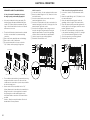
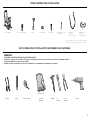
PARTS SUPPLIED FOR INSTALLATION
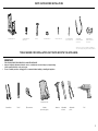
TOOLS NEEDED FOR INSTALLATION (NOT SUPPLIED WITH THE APPLIANCE)
Screwdriver 2 - Wrench
T-handle
wrench
Tape
measurePencil
Adjustable
pliers
Adjustable
wrench
Suitable protective
gloves Drill
Hammer
Screwdriver
Screwdriver 2 - Wrench
T-handle
wrench
Tape
measurePencil
Adjustable
pliers
Adjustable
wrench
Suitable protective
gloves Drill
Hammer
Pencil
Screwdriver 2 - Wrench
T-handle
wrench
Tape
measurePencil
Adjustable
pliers
Adjustable
wrench
Suitable protective
gloves Drill
Hammer
Tape measure
Screwdriver 2 - Wrench
T-handle
wrench
Tape
measurePencil
Adjustable
pliers
Adjustable
wrench
Suitable protective
gloves Drill
Hammer
Suitable
protective gloves
Screwdriver 2 - Wrench
T-handle
wrench
Tape
measurePencil
Adjustable
pliers
Adjustable
wrench
Suitable protective
gloves Drill
Hammer
Hammer Adjustable
wrench
Adjustable
pliers
Screwdriver 2 - Wrench
T-handle
wrench
Tape
measurePencil
Adjustable
pliers
Adjustable
wrench
Suitable protective
gloves Drill
Hammer
Drill
Anti-tip bracket (1) Bolt (1) Threaded nuts (2) Small screws and
washers (2)
Wood screws (8) Ground lead*
(3 wire permanent
connection)
*Can be used in US only, for Canada it is mandatory to
connect the range by using cordset with plug supplied.
==
Screws and plastic
sleeve anchors (8)
Cupped washer*
(4 wire permanent
connection)
==

6
MODEL IDENTIFICATION
OR30SDI6
OR30SCI6
OR30SDE6
NOTE: Model features may vary
30” INDUCTION MODELS 30” CERAMIC MODELS
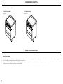
PRIOR TO INSTALLATION
Unpacking and handling
Inspect the range to verify that there is no shipping damage. If any damage is detected, call the shipper and initiate a damage claim. Fisher & Paykel is not responsible for shipping damage.
DO NOT discard any packing material until the range has been inspected.
Remove the outer carton and any packing material from range. Some models are supplied with a protective film on steel and aluminum parts.
This film must be removed before installing or using the appliance.

7
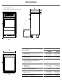
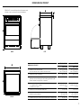
NOTE: Model features may vary
Optional kickstrip shown is available (purchased separately)
PRODUCT DIMENSIONS
FRONT
TOP
SIDE
E
B
C
C
A
D
FG
PRODUCT DIMENSIONS OR30SDI / OR30SCI OR30SDE
inches (mm) inches (mm)
AOverall height of range
(from floor to top of cooktop, excluding optional backguard)
min 35 3/4” (908)
max 37 5/8” (956)
min 35 3/4” (908)
max 37 5/8” (956)
BOverall width of range 29 7/8” (759) 29 7/8” (759)
COverall depth of range
(from front of range to rear of island trim/backguard,
excluding handles and dials)
25 1/4” (641) 25 1/4” (641)
DHeight from top of cooktop to top of
- Island trim (fitted)
- Backguard (optional)
Level with cooktop
3” (76)
Level with cooktop
3” (76)
EHeight of chassis (excluding adjustable feet) 32 1/8” (816) 32 1/8” (816)
FAdjustable feet height min 3 3/8” (85)
max 5 1/4” (133)
min 3 3/8” (85)
max 5 1/4” (133)
GDepth of open door to front of range 16 7/16” (417) 16 7/16” (417)

8
E
F
A
D
B
CC
H
G
Electrical & Gas
(see diagrams following)
COOKING SURFACE
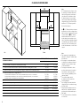
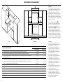
CLEARANCE DIMENSIONS
E
F
A
D
B
CC
H
G
Electrical & Gas
(see diagrams following)
COOKING SURFACE
Note
This range may be installed directly
adjacent to existing 36” (914mm) high
base cabinets.
If the range is to be placed adjacent
to cabinets, the clearances shown are
required. The same clearances apply
to island installations.
The range can be placed in various
positions with respect to the cabinet
front, with the control panel either
flush or projecting, depending on the
cabinetry depth.
The electrical supply should
be within the zones shown in the
following diagrams.
Any openings in the wall behind the
range and in the floor under the range
must be sealed.
Always keep the appliance area clear
and free from combustible materials,
gasoline and other flammable vapors
and liquids.
Do not obstruct the flow of ventilation
air to the unit.
Note
#1 To eliminate the risk of burns or fire
by reaching over heated surface units,
cabinet storage space located above
the surface units should be avoided.
If cabinet storage is to be provided,
the risk can be reduced by installing a
rangehood that projects horizontally a
minimum of 5 “ (127mm) beyond the
bottom of the cabinets.
#2 D=30” (762mm) minimum clearance
between the top of the cooking surface
and the bottom of an unprotected wood
or metal cabinet; or D=24” (610mm)
minimum when bottom of wood or
metal cabinet is protected by not less
than ¼”-thick flame retardant millboard
covered with not less than No. 28 MSG
sheet steel, 0.015”-thick stainless steel,
0.024”-thick aluminum, or 0.020”-thick
copper.
CLEARANCE DIMENSIONS OR30SDI / OR30SCI OR30SDE
inches (mm) inches (mm)
AMinimum width of ventilation hood installed above range 30” (762) 30” (762)
BMinimum vertical distance between countertop and cabinet extending above counter 18” (457) 18” (457)
CMinimum clearance from left and right edge of range to nearest vertical combustible surface 2” (50) 2” (50)
DMinimum clearance from cooking surface to:
– Overhead cabinet centered above the cooktop (combustible/unprotected) - see notes #1, #2
– Overhead cabinet centered above the cooktop (non-combustible/protected) - see notes #1, #2
– Ventilation hood** centered above the cooking surface
30” (762)
24” (610)
24” (610)
30” (762)
24” (610)
24” (610)
EMaximum depth of overhead cabinetry 13” (330) 13” (330)
FWidth of cabinetry opening 30” (762) 30” (762)
GMaximum height of cabinetry immediately adjacent to the range (from floor to countertop)* 37 1/2” (953) 37 1/2” (953)
HMaximum depth from wall to cabinetry face 25 1/4” (641) 25 1/4” (641)
* Depending on the height of the feet adjustment. The cooking surface must sit flush or above countertop level.
** Refer to local/national codes for ventilation requirements.
ISO Front

9
A
B
D
E
C
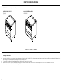
FITTING THE OPTIONAL BACKGUARD
Grounded outlet
The electric cord with 4-prong ground plug
(NEMA 14-50P) shall have a minimum length
of 48” (1220mm) beyond the back of the
range.
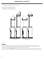
LOCATION OF ELECTRICAL SUPPLY
Final position of cooker against wall
Left side
of cavity
Floor
Electricity
D
B
A AC
SUPPLY AREA DIMENSIONS inches (mm)
ADistance from either edge of
Range to supply area
3/16” (5)
BHeight of electrical supply area
(from floor)
2 3/16” - 4 1/8” * (55-105)*
CWidth of electrical supply areas 29 1/2” (749)
DDepth of supply area (ie
maximum protrusion of electrical
connection from wall)
3 15/16” (100)
* Depending on adjustment of feet
A
B
D
E
C
Island trim and backguard
It is mandatory to install and use the appliance with either
the island trim or the optional backguard correctly in place.
The island trim is already fitted to the appliance while the
backguard can be purchased as a separate kit.
If replacing the island trim with the backguard, assemble it
by using the same screws/spacers used for fixing the island
trim.
7
1
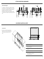
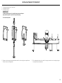
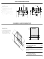
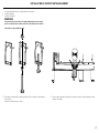
GAS AND ELECTRIC CONNECTION
Fig. 1.2
Dotted line showing the position
of the range when installed
Area for
ELECTRICAL
connection
Area for
GAS connection
C
A
C
D
D
Ref. inch mm
A2” 11/64 - 4” 9/64 (*) 55.2 - 105.2 (*)
B2” 61/64 - 4” 59/64 (*) 75 - 125 (*)
C14” 3/4 374.5
D13/64” 5
(*) : Depending on feet regulation
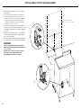
ISLAND TRIM AND BACKGUARD
• It is mandatory to install and use the appliance
with the island trim or backguard correctly in
place.
• The island trim is already tted to the appliance
while the backguard can be purchased as a
separate kit.
• If replacing the island trim with the backguard,
assemble it by using the same screws/spacers
used for xing the island trim (gures 1.3a,
1.3b).
12 x
12 x
Fig. 1.3a
Fig. 1.3b
A
B
A
B
B
7
1
GAS AND ELECTRIC CONNECTION
Fig. 1.2
Dotted line showing the position
of the range when installed
Area for
ELECTRICAL
connection
Area for
GAS connection
C
A
C
D
D
Ref. inch mm
A2” 11/64 - 4” 9/64 (*) 55.2 - 105.2 (*)
B2” 61/64 - 4” 59/64 (*) 75 - 125 (*)
C14” 3/4 374.5
D13/64” 5
(*) : Depending on feet regulation
ISLAND TRIM AND BACKGUARD
• It is mandatory to install and use the appliance
with the island trim or backguard correctly in
place.
• The island trim is already tted to the appliance
while the backguard can be purchased as a
separate kit.
• If replacing the island trim with the backguard,
assemble it by using the same screws/spacers
used for xing the island trim (gures 1.3a,
1.3b).
12 x
12 x
Fig. 1.3a
Fig. 1.3b
A
B
A
B
B

10
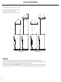
VENTILATION REQUIREMENTS
A suitable ventilation hood may be installed above the range.
Fisher & Paykel has a choice of ventilation hoods designed to
match the rest of our kitchen appliance family.
See fisherpaykel.com or your local dealer for more details.
IMPORTANT
Consult local building codes and/or local agencies, before starting, to ensure that hood and duct installation will meet local requirements.
Hood blower speeds should be variable to reduce noise and loss of heated or air conditioned household air when maximum ventilation is not required.
Normally, the maximum blower speed is only required when grilling or using the self-cleaning cycle.
If a custom hood canopy contains any combustible materials (eg a wood covering) it must be a minimum of 30” (762mm) above the cooking surface.
Due to a high volume of ventilation air, a source of make-up air (outside replacement air) that complies with local codes and regulations is required.
Wall Installation Island Installation
24” (610mm) 24” (610mm)
30” (762mm)
30” (762mm)
Hood (non-combustible)Hood (non-combustible)
Hood (inc. combustible) Hood (inc. combustible)
(for example a
wood surround)
(for example a
wood surround)

11
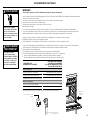
Fitting the adjustable feet
The adjustable feet must be fitted to the base of the range before use.
Rest the rear of the range on a piece of the polystyrene packaging exposing
the base for the fitting of the feet.
IMPORTANT
Take care not to damage the range during this operation.
Fit the four legs by screwing them tight into the support base as shown.
Levelling the range
The range may be levelled by screwing the lower ends of the feet IN or OUT.
Small adjustments may be made to the range in the upright position, however it
may be necessary to tip the range again to make larger adjustments.
Fitting the adjustable feet covers (optional)
If using the adjustable feet covers fit these while the range is tipped over.
FITTING THE ADJUSTABLE FEET
3 Note: gently bend the edges of the
inner cover to adjust the tension
between the two parts if needed.
4 Attach the feet covers to the base of
the range using the supplied screws.
Ensure that the mounting brackets
are aligned with the mounting holes
in the base of the range.
2 Assemble the feet covers by slotting
the inner cover inside the outer
cover.
5 Stand range back upright. 6 Adjust the inner panels of the foot
covers to suit the height of the
range feet as necessary.
1 Tip range onto its back to expose
foot cover mounting hole locations.

12
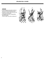
MOVING THE RANGE
IMPORTANT!
When raising the range to upright position always ensure two
people carry out this manoeuvre to prevent damage to the
adjustable feet.
Be careful: do not lift the range by the oven door handle, the
hob rail or the cooktop trim as this may damage the appliance.
When moving range to its final position DO NOT DRAG.
Lift feet clear of floor.

13
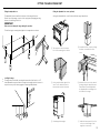
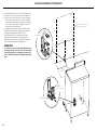
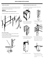
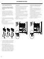
INSTALLING THE ANTI-TIP BRACKET
1 Thread the bolt through the adjustable bracket and fix in place using the two supplied nuts.
Ensure the nuts are well tightened.
2 Fix the adjustable bracket to the back of the range (centered on the lower edge) using the
two supplied screws and washers.
The anti-tip bracket has two components:
the adjustable bracket
the stability bracket
IMPORTANT!
You must install both parts of the anti-tip bracket and ensure they are
properly fitted together to prevent the range from tipping.
To fit the anti-tip bracket
1 2 3

14
INSTALLING THE ANTI-TIP BRACKET
==
Dotted line showing the position
of the range when installed
14 15/16”
(380mm)
3 Fix the stability bracket in place. It can be fixed as follows:
To the floor OR on the rear wall by 4 screws (supplied).
To the floor AND on the rear wall by 8 screws (supplied).
There are 8 x wood screws and 8 x screws with plastic
sleeve anchors supplied with the range in two separate
kits. Use the proper screws according to the type of
material on the floor and/or wall.
If using the the plastic sleeve anchors: drill 5/16” (8mm)
diameter holes and insert the supplied anchors before
attaching the stability bracket with the screws.
4 Slide the range into place, ensuring the bolt on the
adjustable bracket slots under the stability bracket.
Adjust the length of the bolt as necessary. Ensure the two
nuts are well tightened after any adjustments.
IMPORTANT!
Use the proper screws to fix the stability bracket in place
according to the type of material on the floor and/or wall.
Before drilling and holes or inserting any screws into the
floor or wall check that you will not damage any wiring or
pipes.
Stability bracket
Adjustable
bracket with
bolt correctly fitted
Stability bracket

15
ELECTRICAL CONNECTION
Power supply cord with
NEMA 14-50P plug
Standard NEMA 14-50R wall receptacle
IMPORTANT!
This cooker must be connected to the electricity supply only by an authorised person.
Your cooker is supplied with a certified 4 prong NEMA 14-50P power cord for your protection against shock hazard and should be plugged
directly into a properly grounded socket.
Do not under any circumstances cut or remove the forth (ground) prong from the power plug.
Do not ground to a gas pipe.
Do not have a fuse in the neutral or ground circuit.
Do not use an extension cord.
Check with a qualified electrical installer if you are not sure if the range is properly grounded.
If codes permit, and a separate ground wire is used, it is recommended that a qualified electrical technician determines the ground path
and wire gauge are in accordance with local codes.
Be sure that the electrical connection and wire size are adequate and in conformance with:
ANSI/NFPA 70 latest addition and local codes and ordinances.
CSA standard C22.1, Canadian Electrical Code, Part 1 – latest edition and local codes and ordinances.
When a 4-wire, two phase 120/240V or 120/208V 60Hz AC only electrical supply is available a 50 amp maximum circuit protection is
required, fused on both sides of the line.
Replacing the power cord.
Replacements should only be made by qualified electrical technicians.
If replacing the power cord, use only a suitable UL or CSA approved one.
Tighten the power cord using the power cord strain relief bracket supplied with the appliance.
Allow enough slack to easily attach the cord terminals to the terminal block.
Power supply cord with
NEMA 14-50P plug
Standard NEMA 14-50R
wall receptacle
WARNING!
Electrical Shock Hazard
Electricity ground range.
Failure to follow these
instructions can result in death,
fire, or electrical shock.
WARNING!
VERY IMPORTANT
To avoid electrical shock
hazard, before installing the
appliance, switch power OFF
at the service panel and lock
the panel to prevent the
power from being switched
on accidentally.
Location of
nameplate
RANGE RATING * SPECIFIED RATING OF POWER SUPPLIED
CORD KIT AND CIRCUIT PROTECTION
Induction models
AC 120/208 V 60 Hz 11110 W MAX NEC CALCULATED LOAD 40 A*
AC 120/240 V 60 Hz 12340 W MAX NEC CALCULATED LOAD 40 A*
INDUCTION POWER = 7400 W MAX
Ceramic models
AC 120/208 V 60 Hz 8668 W MAX 50 A
AC 120/240 V 60 Hz 11540 W MAX 50 A
* The NEC calculated load is less than the total connected load listed on the rating label.

16
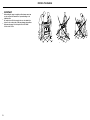
ELECTRICAL CONNECTION
PERMANENT CONNECTION (HARD WIRING)
US only, for Canada it is mandatory to connect
the range by using cordset with plug supplied.
Units may be hard wired to the power supply. The
installer must provide approved flexible aluminium
conduit, 3/4” (19mm) trade size, maximum 6ft (1.8m)
long. Locate the terminal block on the rear of the unit
and remove access cover.
The strain relief bracket orientation must be switched
in order to accommodate for a permanent wiring
connection:
1 Remove the factory supplied power cord with plug.
2 Remove the 2 screws on the bracket.
3 Re-secure bracket with the 2 screws so that the
1 1/8” (29mm) smaller opening is facing down.
The conduit must be installed to the terminal block using
an approved conduit connector. The free end of the
conduit must be connected to a junction box provided in
the electrical supply zone.
Mount a strain relief (not provided) into the 1 1/8”
(29mm) diameter hole located below the terminal block.
Wiring for the unit is to be brought into the terminal
block through the conduit and through the strain
relief. Make suitable connections to the terminal block
provided.
Installer — Show the owner the location of the circuit
breaker. Mark it for easy reference.
4-Wire Connection
1 Loosen the L1 (black), L2 (red) and neutral (white) screws.
2 Mount the conduit fitting to the 1 1/8” (29mm) hole in the
strain relief bracket.
3 Secure the neutral (white) power lead to the center
terminal and tighten the screw.
4 Secure the L1 (black) and the L2 (red) power leads to the
terminals immediately to the left (L1) and right (L2) of the
neutral terminal. Tighten the screws.
5 Secure the Ground (green) lead to the green screw
located to the right of the terminal block using the
supplied cupped washer. The end of the grounding
conductor must be retained by the cupped washer.
6 Check all connections are securely tightened.
7 Reinstall the Terminal Block cover.
3-Wire Connection (using supplied Ground lead)
1 Loosen the L1 (black), L2 (red) and neutral (white)
screws.
2 Mount the conduit fitting to the 1 1/8” (29mm) hole in
the strain relief bracket.
3 Secure the supplied Ground (green) lead to the
grounding screw to the right of the terminal block.
4 Secure the Neutral (white) power lead together with
the free end of the Ground (green) lead to the center
terminal. Tighten the screw.
5 Secure the L1 (black) and the L2 (red) power leads
to the terminals immediately to the left (L1) and right
(L2) of the neutral terminal. Tighten the screws.
6 Check all connections are securely tightened.
7 Reinstall the Terminal Block cover.
1 2 3
Terminal Block
Strain relief bracket Smaller opening
PENL1 L2 NL1 L2
PE
PENL1 L2 NL1 L2
PE

17
TO BE COMPLETED BY THE INSTALLER
GENERAL
Placement of unit.
Specified clearance maintained to cabinet surfaces.
Unit Level – front to back, side to side.
All packaging material and tie straps removed.
Island trim or optional backguard correctly attached.
The anti-tip bracket is correctly installed.
ELECTRICAL
Adequate ground connection.
FINAL CHECKLIST
Complete and keep for safe reference:
Model
Serial No.
Purchase Date
Purchaser
Dealer Address
Installer’s Name
Installer’s Signature
Installation Company
Installation Date
OPERATION
All internal packing materials removed. Check inside the oven.
Dials turn correctly and freely.
Oven and cooktop displays are functioning correctly and oven and cooking zones can
be turned on.
Oven door hinges seated and door opens and closes properly.
Copyright © Fisher & Paykel Appliances 2019. All rights reserved.
The product specifications in this booklet apply to the specific products
and models described at the date of issue. Under our policy of continuous
product improvement, these specifications may change at any time. You
should therefore check with your Dealer to ensure this booklet correctly
describes the product currently available.
FISHERPAYKEL.COM


Modèles à induction OR0SDI et OR0SCI
en verre céramique OR0SDE
CUISINIÈRE NON ENCASTRÉE
GUIDE D’INSTALLATION
US CA
591507D 10.19

TABLE DES MATIÈRES
Consignes de sécurité et mises en garde 3
Pièces fournies pour l’installation 5
Outils requis pour l’installation (non fournis avec l’appareil) 5
Identification du modèle 6
Avant l’installation 6
Dimensions du produit 7
Dimensions de dégagement 8
Installation du dosseret en option 9
Emplacement de l’alimentation en électricité 9
Exigences relatives à la ventilation 10
Installation des pattes ajustables 11
Déplacement de la cuisinière 12
Installation du support antibasculement 13
Raccordement électrique 15
Liste de vérification finale 17
La page est en cours de chargement...
La page est en cours de chargement...
La page est en cours de chargement...
La page est en cours de chargement...
La page est en cours de chargement...
La page est en cours de chargement...
La page est en cours de chargement...
La page est en cours de chargement...
La page est en cours de chargement...
La page est en cours de chargement...
La page est en cours de chargement...
La page est en cours de chargement...
La page est en cours de chargement...
La page est en cours de chargement...
La page est en cours de chargement...
La page est en cours de chargement...
-
 1
1
-
 2
2
-
 3
3
-
 4
4
-
 5
5
-
 6
6
-
 7
7
-
 8
8
-
 9
9
-
 10
10
-
 11
11
-
 12
12
-
 13
13
-
 14
14
-
 15
15
-
 16
16
-
 17
17
-
 18
18
-
 19
19
-
 20
20
-
 21
21
-
 22
22
-
 23
23
-
 24
24
-
 25
25
-
 26
26
-
 27
27
-
 28
28
-
 29
29
-
 30
30
-
 31
31
-
 32
32
-
 33
33
-
 34
34
-
 35
35
-
 36
36


Fisher & Paykel OR30SCI6B1 Guide d'installation
- Catégorie
- Cuisinières
- Taper
- Guide d'installation
