Frigidaire 5304526182 Guide d'installation
- Taper
- Guide d'installation

use
&
care
FOOD WASTE DISPOSER
English ..............................................................2
Français ........................................................... 15
Espanol .......................................................... 29
p/n 5304525393

2
Record important disposer information here:
Model Number* Serial Number*
Í
NOTE
This Food Waste Disposer has been designed to operate on
110-120V, 60 Hz exclusively. Using any other voltage or Hz ad-
versely a ects performance.
CAUTION
Be sure to review SAFETY INSTRUCTIONS FIRST
PERTAINING TO A RISK OF FIRE, ELECTRICAL SHOCK
OR INJURY TO PERSONS before using disposer.
IMPORTANT
Read all instructions thoroughly. Keep this guide for
future reference.
*Above information appears on the label a xed to bottom
of the disposer. For your convenience, write down the
model and serial number prior to installation.
IMPORTANT SAFETY INFORMATION
WARNING
When using electrical appliances, basic
precautions should always be followed,
including the following:
INSTRUCTIONS PERTAINING TO A RISK OF FIRE,
ELECTRIC SHOCK OR INJURY TO PERSONS. SAVE
THESE INSTRUCTIONS.
1. Read all instructions before using the appliance.
2. To reduce the risk of injury, close supervision is necessary
when an appliance is used near children.
3. Do not put fi ngers or hands into a waste disposer.
4. Turn the power switch to the o position before
attempting to clear a jam or remove an object from the
disposer.
5. When attempting to loosen a jam in a waste disposer, use
a long wooden object such as a wooden spoon or the
wooden handle of a broom or mop.
6. When attempting to remove objects from a waste
disposer use long-handled tongs or pliers. If the disposer
is magnetically actuated, non-magnetic tools should be
used.
7. To reduce the risk of injury by materials that may be
expelled by a waste disposer, do not put the following
into a disposer: clam or oyster shells; caustic drain
cleaners or similar products; glass, china or plastic;
large whole bones; metal, such as bottle caps, tin cans,
aluminum foil or utensils; hot grease or other hot liquids;
whole corn-husks.
8. When not operating a disposer, leave the stopper in place
to reduce the risk of objects falling into the disposer.
9. DO NOT operate disposer unless splash guard is in place.
10. For proper grounding instructions see the ELECTRICAL
CONNECTIONS portion of this manual.
11. If the supply cord is damaged, it must be replaced by the
manufacturer, its service agent, or authorized person in
order to avoid hazard.
12. This appliance is not intended for use by persons
(including children) with reduced physical, sensory or
mental capabilities, or lack of experience and knowledge,
unless they have been given supervision or instruction
concerning use of the appliance by a person responsible
for their safety.
13. Children should be supervised to ensure that they do not
play with the appliance.
The receptacle to which this appliance is connected
must be controlled by a switch.
Having Problems? Don't go back to the store.
Call us toll-free at 1-833-240-6224 for assistance.
M-F 8:00am-5:00pm PST English & Spanish
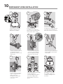
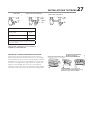
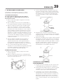
3-BOLT MOUNTING SYSTEM

33
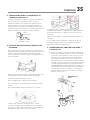
REMOVAL OF OLD UNIT
IMPORTANT
This is a good time to clean out the trap and drain lines by
running a drain auger or plumber’s snake before installing
your new disposer.
CAUTION
Be sure to support the disposer while performing this step or
it may fall when the mounting ring is disconnected from the
mounting assembly.
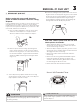
1. REMOVAL OF OLD UNIT
TYPICAL INSTRUCTIONS, YOUR MODEL MAY VARY.
Before starting this step, turn o electrical
power at the circuit breaker or fuse box. Unplug
disposer.
If your installed mount is the same type as the mount on your
new disposer and you wish to continue to use the already
installed mount, proceed to section 3 on the Connection page.
If your new mount system is di erent or if you wish to use the
new mount, follow these instructions:
A. Have a container available to catch any excess water/
waste from current disposer. Use a pipe wrench to
disconnect drain line where it attaches to disposer
discharge elbow (see 1A).
B. Remove disposer from sink fl ange by turning mount
ring to the left clockwise (see 1B). If you are unable to
turn the mount ring, tap on one of the extensions from
the ring with a hammer. Some mounting systems have
tubular extensions. Inserting a screwdriver into one tube
will provide additional leverage for turning the mount
ring (see 1B).
C. Some disposers may require the removal or loosening
of nuts from the mount screws (see 1C). Some disposers
may require the removal of a clamp.
D. To remove remaining mount system from the sink, loosen
mount screws, push mount ring up. Under it is the retainer
ring. Use screwdriver to pop o ring (see 1D). Remove
mount ring, protector ring and gasket from sink fl ange.
Some mounts will require the unscrewing of a large
ring holding the sink fl ange in place. Pull sink fl ange up
through sink and clean o old putty from sink.
E. Ensure that sink is clean and thoroughly dry.
1A
1B
1C
1D
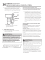
If you have a mount system under the sink that
is black plastic with threads:
A. While holding the disposer in place, turn the metal
mount ring clockwise (1E). If it is hard to turn, tap the
ear of the mount ring clockwise.
B. When the disposer hopper projections get close to the
mount ring opening, hold the disposer from bottom and
disengage it from the mount ring.
C. Remove the rubber cushion mount from under the
mount ring.
D. Remove the mount ring. Unthread the black support
ring from sink fl ange by turning the support ring
clockwise. Remove the fi ber gasket and then remove
the sink fl ange from above the sink.
E. Ensure that sink is clean and thoroughly dry.
1E
Mount With Threaded Flange

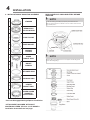
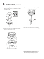
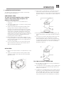
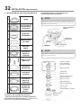
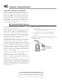
4INSTALLATION
A STOPPER
BREMOVABLE
SPLASH GUARD
CSINK FLANGE
DFIBER GASKET
ESUPPORT
FLANGE
FUPPER
MOUNT RING
GMOUNT
SCREWS
HRETAINER RING
I CUSHION RING
JLOWER
MOUNT RING*
K
SILVER GUARD®
MAGNETIC
CATCH RING**
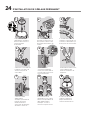
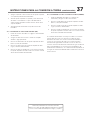
2. INSTALLATION OF MOUNTING ASSEMBLY
**ATTACHMENT INCLUDED WITH MOST
CONTINUOUS FEED 3/4 HP & 1-¼ HP MODELS.
Installation instructions on last page.
READ CAREFULLY AND COMPLETELY BEFORE
STARTING
Í
NOTE
As the mounting assembly is properly assembled at the
factory, please pay close attention to the order of the mount-
ing system parts.
Í
NOTE
Cushion Ring included between the Upper Mount Ring and
Lower Mounting Ring.
* Part not disengaged during disposer installation.

55
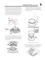
INSTALLATION (CONTINUED)
A. The Cushion Ring and the Lower Mount Ring will remain
attached to the disposer during installation. Take apart
the other parts of the mounting assembly by rotating the
Lower Mount Ring clockwise until the Lower Mount Ring
Tabs slide o from the Upper Mount Ring ramp (see A1).
This allows you to pull the Sink Flange up and out of the
remaining Lower Mount Assembly. Note the order of these
parts as they are arranged in the required order. Unscrew
the 3 Mount Screws until the Upper Mount Ring can be
moved to the top of the Support Flange. Remove the
Retainer Ring with a fl at head screw driver (see A2).
B. Keep the remaining parts placed together in the order
they were removed (see B1). Before you connect the
disposer to the mount assembly under the sink, make sure
the Lower Mount Ring is in place and the black Cushion
Ring is still engaged properly to the top of the disposer
hopper (see B2).
C. Be sure the sink is clean. Load the underside rim of the
sink fl ange with plumber’s putty (see C1). From top of
the sink, push the sink fl ange down against the sink
opening to make a good seal (see C2). DO NOT MOVE
OR ROTATE the sink fl ange once it has been seated or
the seal may be broken.
D. Place a heavy object, such as the disposer
(use a towel to prevent sink scratching) on
top of the Sink Flange to hold it down.

6
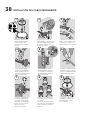
E. Take the remaining portion of the mount assembly that was
put aside. From under the sink insert the Fiber Gasket (see
E1), then the Support Flange (see E2), and then the Upper
Mount Ring (see E3).
F. Hold the three parts in place while attaching the Retainer
Ring (see F1) by pulling it apart and having it snap within
the groove of the sink fl ange (see F2).
G. Tighten the three Mount Screws evenly and fi rmly against
the Support Flange (see G1). Do not over tighten.
H. Trim o any excess plumber’s putty in the sink with a
plastic knife or something similar that will not damage your
sink.
INSTALLATION (CONTINUED)
Having Problems? Don't go back to the store.
Call us toll-free at 1-833-240-6224 for assistance.
M-F 8:00am-5:00pm PST English & Spanish

77
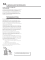
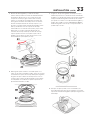
3. DISHWASHER CONNECTION PREPARATION
CONNECTION
If you are utilizing a dishwasher, complete the
following procedure.
Using a blunt instrument (steel punch or wooden dowel),
knock out entire plug. Do not use a screwdriver or sharp
instrument. (When knockout plug falls into disposer, you may
remove it or grind it up when the disposer is used. This will
not damage the disposer in any way, but it may take some
time to grind).
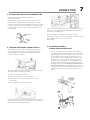
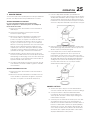
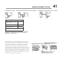
4. LOCKING MOUNTING ASSEMBLY DETAIL
Attach disposer onto the Upper Mount Ring by aligning
the three mount tabs on the Lower Mount Ring with the
slide-up Ramps on the Upper Mount Ring and rotating
counterclockwise. See Below.
The Lower Mount Ring (which is part of the disposer) has 3
tabs that grab the mounting ring ramp.
(A) points to the Upper Mount Ring.
(B) is the tab that slides up onto the “Ramp”.
(C) is the “Ear” that is used to help rotate the Lower
Mount Ring.
Use a screwdriver for leverage if needed.
Lift and turn the Lower Mount Ring counterclockwise until
all three mount tabs lock over the Ridges (F) on the slide-up
Ramps (D) of the Upper Mount Ring.
As the Lower Mount Ring is turned counterclockwise each tab
slides up onto the Upper Mount Ring Ramp (E) and locks in
position over the Ridges (F).
Use a screwdriver or hammer for leverage if needed.
If a disposer needs to be removed, tapping on the Ear clockwise
with a hammer will easily loosen the Lower
Mount Ring.
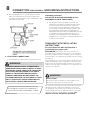
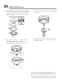
5. DISCHARGE ELBOW &
DISHWASHER CONNECTIONS
A. Connect the waste elbow to the disposer by sliding
the fl ange against the rubber gasket on the elbow and
tightening the screws into the disposer (see 5A). Then
connect bottom of the elbow by tightening the slip
nut (see 5B). If using a straight pipe, it must have a lip
similar to the one on the elbow. Remove the gasket
from the elbow and install it on the straight pipe with
the fl at end of the gasket facing toward the disposer
discharge opening. IF YOU ARE NOT CONNECTING TO
A DISHWASHER make sure all plumbing connections
are tight and in accordance with all plumbing codes and
ordinances. Run water and check for leaks. Go on to
Step 6.
KNOCK OUT
PLUG
WOOD OR
METAL DOWEL

8
B. Connect dishwasher hose (see 5C) using hose clamp.
Make sure all plumbing connections are tight and in
accordance with all plumbing codes and ordinances. Run
water and check for leaks.
CONNECTION (CONTINUED) & GROUNDING INSTRUCTIONS
6. ELECTRICAL CONNECTIONS
A. Connect disposer to appropriate household current only.
WARNING
IMPROPER CONNECTION OF THE EQUIPMENT-
GROUNDING CONDUCTOR CAN RESULT IN A RISK
OF ELECTRIC SHOCK. CHECK WITH A QUALIFIED
ELECTRICIAN OR SERVICEMAN IF YOU ARE IN
DOUBT AS TO WHETHER THE APPLIANCE IS
PROPERLY GROUNDED. DO NOT MODIFY THE
PLUG PROVIDED WITH THE APPLIANCE IF IT WILL
NOT FIT THE OUTLET. HAVE A PROPER OUTLET
INSTALLED BY A QUALIFIED ELECTRICIAN.
The receptacle to which this appliance is
connected must be controlled by a switch.
Grounding Instructions
FOR WASTE DISPOSERS EQUIPPED WITH A
GROUNDED PLUG-IN POWER CORD.
B. This appliance must be grounded. In the event of a
malfunction or breakdown, grounding provides a path
of least resistance for electric current to reduce the
risk of electric shock. This appliance is equipped with
a cord having an equipment-grounding conductor and
a grounding plug. The plug must be plugged into an
appropriate outlet that is properly installed and grounded
in accordance with all local codes and ordinances. If
the supply cord is damaged it must be replaced by the
manufacturer, its service agent or similarly qualifi ed person
in order to avoid a hazard.
PERMANENT WIRE INSTALLATION
INSTRUCTIONS
For waste disposers NOT equipped with a
grounded plug-in power cord.
GROUNDING: This disposer must be connected to a
grounded, metal, permanent wiring system; or an equipment-
grounding conductor must be run with the circuit conductors
and connected to the equipment-grounding terminal or lead on
the disposer.
An acceptable motor control switch with a marked o position
shall be provided at the time of installation to disconnect the
disposer from all ungrounded supply conductors. The switch
shall be mounted in sight of the disposer or in sight of the sink
opening for the disposer.
WARNING
Electric Shock
Turn o power before installing or servicing disposer. All
wiring must comply with local electrical codes.
Do not connect electrical current at main breaker panel until
adequate ground is established. Inadequate connection of
the ground wire can result in a risk of electric shock. Consult
with a certifi ed electrician or tradesman if there is any doubt
whether the disposer in inadequately grounded. Your
disposer must be adequately grounded.

99
GROUNDING INSTRUCTIONS (CONTINUED)
1. Turn o or disconnect all power to the wall junction box
serving the disposer.
2. Open the junction box in the wall and remove the wire
nuts or electrical tape or whatever is tying the old
disposer wire to the electrical wire inside of the junction
box.
3. Open the end bell plate at the bottom or the disposer.
If you are using fl exible armored (BX) cable:
1. Install cable fi tting in the disposer end bell hole.
2. Secure the cable to the fi tting and install an insulating
bushing or equivalent.
3. Connect white wire from the junction box to the white
(or blue) wire of the disposer.
4. Connect black wire from the junction box to the black (or
brown) wire of the disposer.
5. Connect bare ground wire from the junction box to green
ground screw within the disposer end bell.
If you are using nonmetallic-sheathed (ROMEX)
cable:
1. Install cable fi tting in the end bell hole and secure the
cable to the fi tting.
2. Connect white wire from the junction box to the white
(or blue) wire of the disposer.
3. Connect black wire from the junction box to the black (or
brown) wire of the disposer.
4. Connect bare ground wire from the junction box to green
ground screw within the disposer end bell.
If your power supply cable does not include a grounding wire,
one must be provided. Attach a copper wire securely to the
disposer ground screw and attach other end of ground wire
to a metal cold water pipe. Do not attach ground wire to a gas
supply pipe. Use only UL Listed grounding clamp. If plastic
pipe is used in your home, a qualifi ed electrician should install a
proper ground.
Having Problems? Don't go back to the store.
Call us toll-free at 1-833-240-6224 for assistance.
M-F 8:00am-5:00pm PST English & Spanish

10
123
879
456
1. After turning o power
supply, unbolt two nuts
and remove end plate.
2. Using a flathead
screwdriver or needle nose
pliers, remove clip from strain
relief portion of the cord.
3. Using wire cutters, cut black
(or brown) wire and white (or
blue) wire near the connectors.
4. Pull cord strain relief out
of endbell. Cut green
ground wire near the cord
strain relief.
5. Insert metal strain relief
connector (not included)
into the endbell hole and
tighten the nut securely.
6. Strip the green, black, and
white insulation from last ½”
of each wire.
7. Insert the power supply
cable, coming from the
wall junction box,
through the strain relief
connector. Tighten
connector.
8. Connect disposal wire leads
(black and blue) to
corresponding wire leads of
the power supply cable.
Green always connects to
green.
9. Setting the wires into
the endbell, replace the
end plate and tighten the
two bolts.
PERMANENT WIRE INSTALLATION

1111
Your disposer is Continuous Feed if you did not specifi cally
purchase a Batch Feed Disposer.
7. OPERATING INSTRUCTIONS
CONTINUOUS FEED
The Anti-Jam Swivel Impellers make a clicking
sound as they initially swing into place. This
indicates normal operation.
A. Remove sink stopper. Turn on a medium fl ow of
cold water.
B. Turn switch to ON position; your motor is turning at full
speed and ready to use.
C. Scrape in food waste. Down the drain go table scraps,
peelings, rinds, seeds, pits, small bones and co ee
grounds. To speed up food waste disposal, cut or break
up large bones, rinds and cobs. Large bones and fi brous
waste require considerable grinding time and are more
easily thrown away with other trash. Do not be alarmed
that the disposer slows down while grinding. The disposer
is actually increasing torque (grinding power) and is
operating under normal conditions.
D. Before turning disposer o , let water and disposer run
for approximately 15 seconds after shredding or grinding
stops. This assures that all waste is thoroughly fl ushed
through trap and drain.
E. It is not recommended to use hot water while running
disposer. Cold water will keep waste and fats solid so
disposer can fl ush away particles.
BATCH FEED
A. Remove sink stopper and turn on a medium fl ow of cold
water.
B. Scrape in food waste. Down the drain go table scraps,
vegetable peelings, cobs, rinds, pits, bones and co ee
grounds (see A).
C. Insert stopper to start disposer (see B). One of the two
small slots in stopper base must line up with switch
plunger inside the neck of the disposer. Push down fi rmly
to turn the disposer on. Lift stopper to shut the disposer
o .
D. Run disposer for 15 seconds after shredding stops. This
ensures that all waste is thoroughly fl ushed through the
drain.
E. To fi ll sink, insert stopper and align the largest slot with
the switch plunger (see C). Push down to seal sink
without starting the disposer. When the large sized slot
in stopper base is lined up with the switch plunger, water
can drain, but tableware, etc., cannot be accidentally
dropped into disposer.
TIPS FOR SUCCESSFUL OPERATION
A. Be sure disposer is empty before using your dishwasher
so it may drain properly.
B. You may want to leave the stopper in the sink drain when
not in use to prevent utensils and foreign objects from
falling into the disposer.
C. Your disposer is ruggedly built to give you many years of
trouble free service. It will handle all normal food wastes,
but it will NOT grind or dispose of such items as plastic,
tin cans, bottle caps, glass, china, leather, cloth, rubber,
string, clam and oyster shells, aluminum foil or feathers.
OPERATION

12 CLEANING AND MAINTENANCE
DO NOT ATTEMPT TO LUBRICATE
YOUR DISPOSER!
The motor is permanently lubricated. The disposer is self cleaning
and scours its internal parts with each use. NEVER put lye or
chemical drain cleaners into the disposer, as they cause serious
corrosion of metal parts. If used, resulting damage can be easily
detected and all warranties are void. Mineral deposits from
your water can form on the stainless steel turntable, giving the
appearance of rust. DO NOT BE ALARMED, the stainless steel
turntables used will not corrode.
Having Problems? Don't go back to the store.
Call us toll-free at 1-833-240-6224 for assistance.
M-F 8:00am-5:00pm PST English & Spanish
TROUBLESHOOTING
Before seeking repair or replacement, we recommend that you
review the following:
LOUD NOISES: (Other than those during grinding of small
bones and fruit pits): These are usually caused by accidental
entry of a spoon, bottle cap or other foreign object. To correct
this, turn o electrical switch and water. After disposer has
stopped, remove splash guard, remove object with long handled
tongs, and replace splash guard.
UNIT DOES NOT START: Unplug power cord or turn either the
wall switch or breaker box switch to “OFF” position, depending
on your model and wiring confi guration. Remove stopper and/or
splash guard. Check to see if turntable will rotate freely using a
wooden broom handle. If turntable rotates freely, replace splash
guard and check reset button to see if it has been tripped. Reset
button is red and located on the front of the disposer. Push
button in until it clicks and remains depressed.
If reset button has not been tripped, check for shorted or
broken wire connecting to disposer. Check electrical power
switch, fuse box or circuit breaker. If wiring and electrical
components are intact, the unit may have internal problems that
require service or replacement.
IF TURNTABLE DOES NOT ROTATE FREELY: Turn o disposer,
then check for any foreign object lodged between the turntable
and grind ring. Dislodge object by rotating table with a wooden
broom handle (see 8A) and remove object. If no foreign object
is present, there may be internal problems.
LEAKS: If the unit leaks at the top, it may be due to:
1. Improper seating of sink fl ange (gasket centering, putty
or tightening).
2. Support fl ange not tightened properly.
3. Defective or improperly installed cushion mount.
If unit leaks at the waste elbow, leak may be due to improper
tightening of elbow fl ange screws.
8A

1313
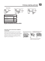
*Approximate Dimension
1/3 HP, 1/2 HP & 3/4 HP Slim-
Line Models 10.2 in
3/4 HP Deluxe 10.5 in
1-1/4 HP Premium 10.5 in
Batch Feed units add approx. 2.1”/53mm
TYPICAL INSTALLATIONS
MOUNTING THE SILVER GUARD® MAGNETIC
CATCH RING
After the disposer is fully mounted to the sink, guide the
Magnetic Silver Guard® through the mount screws (6A)
with the fl at portion of the black strap facing the metal sink
fl ange. Place the Silver Guard® between the Support Flange
and Upper Mount Ring. Please note (6B) that the Silver
Guard® must be placed under the fl ange of the Support
Ring. Once the Silver Guard® is fi tted, fi rmly press on the
snaps to secure the strap (6C).
For your specifi c disposer dimensions, contact
Frigidaire customer service at 1-833-240-6224.

www.frigidaire.com USA 1-800-374-4432 www.frigidaire.ca Canada
14 LIMITED LIFETIME WARRANTY AGAINST FAILURE DUE TO CORROSION
1-833-240-6224
10200 David Taylor Drive
Charlotte, NC 28262
Model Horsepower Warranty Period
1/3 HP 5 years
1/2 HP 6 years
3/4 HP 10 years
1-1/4 HP 12 years
Proof of purchase is required! Staple receipt or proof of purchase to this manual. Tracking is handled through the
serial number a xed to the bottom of the disposer and/or on the power cord label.
Conveniently record your model number and serial number on the front of this manual for your records. If
you need warranty service, call us toll-free at 833-240-6224. Have serial number and receipt available for the
technician. Warranty is non-transferable.
1. WARRANTY: Frigidaire disposers are warranted when installed in the United States to be free from defects in workmanship
and material during the warranty period. This warranty sets forth our overall warranty commitment. We will not assume, nor
authorize any person to assume for us, any other liability in connection with the sale of our products. Warranty only valid for
product sold through authorized dealers/retailers.
2. LENGTH OF WARRANTY: 1/3 HP MODELS - 5 years from date of purchase. 1/2 HP MODELS - 6 years from date of
purchase. 3/4 HP MODELS - 10 years from date of purchase. 1 ¼ HP MODELS - 12 years from date of purchase. Models that
fail to operate during its warranty period, will be repaired or replaced. This Warranty includes In-Home Warranty for Frigidaire
models that fall into disrepair due to manufacturing defect. This warranty is limited to the original purchaser. Original sales
receipt required.
3. DEFECTIVE DISPOSER: During the warranty period, a defective or inoperative disposer will be replaced by the company
at no charge to the consumer/purchaser. Original sales receipt required. The warranty on the replacement will be limited
to the unexpired term of the warranty on the original disposer.
4. CHANGE OF OWNERSHIP DISPOSER: Warranty remains in force for warranty period from date of purchase of disposer
by the original retail customer. Warranty is non-transferable. Original sales receipt required.
5. MISUSE OF DISPOSER: This warranty does not apply to any disposer which is misused, altered, improperly installed
or used for anything other than normal residential use. Additional conditions not covered by the warranty are as follows:
Electrical connections due to improper installation; leaks at the sink fl ange, dishwasher inlet or discharge elbow; damage by
installer such as excessive torquing of screwed connections; incorrect operation such as grinding nonfood waste; and jams.
6. HOW TO RECEIVE SERVICE: Contact our Customer Service department: Toll Free: (833-240-6224).
7. LIFETIME CORROSION WARRANTY: In addition to above warranty, any disposer that fails to operate because of
corrosion will be replaced. This Lifetime Corrosion warranty is limited to the original purchaser. Original sales receipt is
required.
8. MODEL NUMBER AND SERIAL NUMBER: The model number and serial number are located on the bottom serial plate of
your disposer and/or the power cord tag. Always reference the model number and serial number when contacting customer
service about any warranties on your disposer.
9. IMPLIED WARRANTIES: IMPLIED WARRANTIES, INCLUDING IMPLIED WARRANTIES OF MERCHANTABILITY AND
FITNESS FOR A PARTICULAR PURPOSE, ARE LIMITED IN DURATION TO WARRANTY PERIOD FROM THE DATE OF
PURCHASE. Some states do not allow limitations on how long an implied warranty lasts, so therefore the above limitation may
not apply to you.
10. CONSEQUENTIAL OR INCIDENTAL DAMAGES: THE COMPANY SHALL NOT BE LIABLE FOR CONSEQUENTIAL OR
INCIDENTAL DAMAGES FOR ANY BREACH OF WARRANTY, EXPRESS OR IMPLIED. Some states do not allow the exclusion
or limitation of the consequential or incidental damages, so therefore the above exclusion may not apply to you.
11. EXCLUSIVE REMEDY; CONSEQUENTIAL DAMAGES: The foregoing provisions state the exclusive remedy for any
breach of warranty, express or implied, TO THE EXTENT PERMITTED BY LAW, THE COMPANY SHALL NOT BE LIABLE FOR
CONSEQUENTIAL OR INCIDENTAL DAMAGES FOR BREACH OF WARRANTY, EXPRESS OR IMPLIED. Some states do not
allow the exclusion or limitation of consequential or incidental damages, so therefore the above exclusion may not apply to
you.
This warranty gives you specifi c legal rights, and you may also have other rights which vary from State to State.
Having Problems? Don't go back to the store.
Call us toll-free at 1-833-240-6224 for assistance.
M-F 8:00am-5:00pm PST English & Spanish

15
www.frigidaire.com USA 1-800-374-4432 www.frigidaire.ca Canada
1-800-265-8352
BROYEUR À DÉCHETS
Manuel d'utilisation
Système de montage à 3 boulons
Í
REMARQUE
Ce broyeur de déchets alimentaires a été conçu pour fonc-
tionner exclusivement sur une alimentation secteur de 110-
120V, 60 Hz. Tout autre tension ou fréquence risque d’altérer
ses performances.
AVERTISSEMENT
Assurez-vous de consulter les CONSIGNES DE SÉCURITÉ
PORTANT SUR LES RISQUES D'INCENDIE, DE CHOC ÉLEC-
TRIQUE OU DE BLESSURES avant d'utiliser ce broyeur.
IMPORTANT
Lisez attentivement toutes les instructions. Conservez
ce manuel pour consultation future.
Inscrivez ici les informations importantes concernant les broyeurs :
Numéro de modèle* Numéro de série
Anglais (2)
Français (15)
Espanol (29)
Vous avez un problème? Ne le retournez pas au magasin.
Appelez-nous sans frais au 1-833-240-6224 pour de l’assistance.
L-V 8:00am-5:00pm PST Anglais et Espagnol
*Les renseignements ci-dessus apparaissent sur l’étiquette fi xée sous le
broyeur. Pour votre commodité,
prenez en note les numéros de modèle et de série avant l’installation.

16 IMPORTANTES CONSIGNES DE SÉCURITÉ
AVERTISSEMENT
Lors de l'utilisation d'appareils électriques,
des précautions de base doivent toujours être
prises, notamment les suivantes :
CONSIGNES RELATIVES AUX RISQUES
D'INCENDIE, D'ÉLECTROCUTION OU DE
BLESSURES. VEUILLEZ CONSERVER CES
CONSIGNES.
1. Lire attentivement toutes les instructions avant d'utiliser
l'appareil.
2. Pour réduire le risque de blessures, une étroite
supervision est nécessaire lorsqu'un appareil est utilisé à
proximité de jeunes enfants.
3. Ne pas mettre les doigts ou les mains dans un broyeur à
déchets.
4. Mettre l'interrupteur à la position d'arrêt avant de tenter
de débloquer ou de retirer un objet du broyeur.
5. Lorsque vous essayez de décoincer un bouchon dans
un broyeur à déchets, utilisez pour cela un long objet en
bois comme une cuillère en bois ou le manche en bois
d'un balai ou d'une serpillière.
6. Utiliser des pinces à longues poignées ou des pinces
de plombier pour enlever des objets le broyeur. Si le
broyeur est actionné magnétiquement, des outils non
magnétiques doivent être utilisés.
7. Pour réduire le risque de blessure par des matières
pouvant être expulsées par un broyeur de déchets,
évitez de mettre dans un broyeur les produits suivants
: coquilles de palourdes ou d'huîtres, nettoyants
caustiques pour canalisations ou produits similaires,
verre, porcelaine ou plastique, gros os entiers, métal, tel
que capsules de bouteilles, boîtes de conserve, papier
d'aluminium ou ustensiles, graisse chaude ou autres
liquides chauds, enveloppes de maïs entières.
8. Lorsque le broyeur n'est pas en fonction, laisser le
bouchon en place pour réduire le risque que des objets
tombent dans le broyeur.
9. Ne PAS faire fonctionner le broyeur lorsque le protecteur
anti-éclaboussures n'est pas en place.
10. Pour plus de détails sur les instructions de mise à la terre
voir la section RACCORDEMENT ÉLECTRIQUE de ce
manuel.
11. Si le cordon d'alimentation est endommagé, il doit
être remplacé par le fabricant, son représentant ou
une personne qualifi ée de façon éviter tout risque
d'électrocution.
12. Cet appareil n'est pas destiné à être utilisé par des
personnes (y compris des enfants) dont les capacités
physiques, sensorielles ou mentales sont réduites ou
qui manquent d'expérience et de connaissances, sauf
si elles ont été encadrées ou ont reçu des instructions
concernant l'utilisation de l'appareil par une personne
responsable de leur sécurité.
13. Il est recommandé de surveiller les enfants afi n de
s'assurer qu'ils ne jouent pas avec l'appareil.
Le réceptacle auquel est raccordé cet appareil
doit être contrôlé au moyen d’un interrupteur.
Vous avez un problème? Ne le retournez pas au magasin.
Appelez-nous sans frais au 1-833-240-6224 pour de l’assistance.
L-V 8:00am-5:00pm PST Anglais et Espagnol

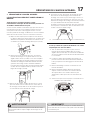
17
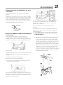
IMPORTANTE
C'est un bon moment pour net-toyer les conduits d'évacua-
tion à l'aide d'un furet ou d'une sonde spirale avant d'installer
le nouveau broyeur
AVERTISSEMENT
Assurez-vous de soutenir le broyeur au cours de cette étape
car il pourrait tomber lorsque la bague de montage est dé-
connectée.
1. DÉMONTAGE DE L’ANCIEN APPAREIL
LES INSTRUCTIONS PEUVENT VARIER SELON LE
MODÈLE.
Avant de passer à l'étape suivante, coupez
l'alimentation électrique de la boîte de disjoncteurs ou
de fusibles. Débranchez le broyeur.
Si votre monture installée est du même type que celle de votre
nouveau broyeur et que vous souhaitez continuer à vous en
servir, passez à la section 3 de la page Connexion. Si votre
nouveau système de montage est di érent ou si vous souhaitez
utiliser la nouvelle monture, suivez les instructions suivantes :
A. Disposez d'un récipient pour récupérer l'excès d'eau ou
les déchets du broyeur actuel. Utilisez une clé à pipe pour
débrancher la tuyauterie d'évacuation à l'endroit où elle
se rattache au coude de décharge du broyeur (voir 1A).
B. Retirez le broyeur de la bride de l'évier en tournant
l'anneau de montage vers la gauche dans le sens des
aiguilles d'une montre (voir 1B). Si vous êtes incapable
de tourner la bague de montage, frappez sur l'une des
extrémités de la bague à l'aide d'un marteau. Certains
systèmes de montage ont des extrémités tubulaires.
L'insertion d'un tournevis dans un tube permet d'obtenir
un e et de levier supplémentaire pour faire tourner la
bague de montage (voir 1B).
C. Dans le cas de certains modèles de broyeurs, il se peut
que vous deviez enlever ou desserrer les écrous des vis
de montage (voir 1C). Dans le cas de certains broyeurs, il
est nécessaire de retirer la bride de serrage.
D. Pour retirer le reste du système de montage de l'évier,
desserrez les vis de montage, poussez l'anneau de
montage vers le haut. Le jonc de blocage se trouve en-
dessous. Utilisez un tournevis pour enlever le jonc (voir
1D). Enlevez la bague de montage, l'anneau de protection
et le joint d'étanchéité du collet d'évier. Certains
montages nécessitent le dévissage d'un gros anneau qui
tient en place le collet d'évier. Tirez le collet d'évier vers
le haut et enlevez le mastic usagé.
E. Assurez-vous que l’évier est propre et entièrement sec.
1A
1B
1C
1D
Si vous possédez un système de fi xation sous l’évier
en plastique noir avec des fi lets:
A. Tout en maintenant le broyeur en place, tournez
l'anneau de montage métallique dans le sens des
aiguilles d'une montre (1E). Si vous avez de la di culté
à le touner, frappez l’oreille de l’anneau de fi xation dans
le sens horaire.
B. Lorsque les saillies de la chambre de broyage sont
près de l’ouverture de l'anneau de fi xation, maintenez
le broyeur par le bas et désengagez-le de l’anneau de
fi xation.
C. Retirez l’assemblage coussiné en caoutchouc sous
l’anneau de fi xation.
D. Retirez l’anneau de fi xation. Dévisser l’anneau de
support noir du collet d’évier en tournant l’anneau
de support dans le sens horaire. Retirez le joint
d'étanchéité en fi bre puis retirez le collet d’évier de
l’évier.
E. Assurez-vous que l’évier est propre et entièrement sec.
1E
Fixation avec collet vissé
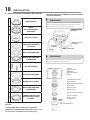
DÉMONTAGE DE L’ANCIEN APPAREIL

18
A OBTURATEUR
B
PARE -
ÉCLABOUSSURES
AMOVIBLE
CCOLLET D’ÉVIER
DJOINT D’ÉTANCHÉITÉ
EN FIBRE
EBAGUE DE MONTAGE
FBAGUE DE MONTAGE
SUPÉRIEURE
GVIS DE FIXATION
HBAGUE DE RETENUE
IANNEAU COUSSINET
JBAGUE DE MONTAGE
INFÉRIEURE*
K
ANNEAU DE CAPTURE
MAGNÉTIQUE SILVER
GUARD®**
2. INSTALLATION DE L’ENSEMBLE DE FIXATION
**ACCESSOIRE INCLUS AVEC LA PLUPART DES
MODÈLES D'ALIMENTATION CONTINUE 3/4 HP & 1-1/4
HP. Instructions d'installation en dernière page.
Í
REMARQUE
Comme l’ensemble de fi xation est assemblé adéquatement
à l’usine, veuillez porter une attention particulière à l’ordre
d’assemblage des pièces du système de fi xation.
Í
REMARQUE
L’anneau coussinet inclus entre la bague de montage supé-
rieure et la bague de montage inférieure.
*Partie non désolidarisée lors de l'installation du
broyeur.
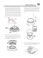
BAGUE DE MONTAGE
INFÉRIEURE
PATTE DE
MONTAGE
ENTRÉE DU LAVE-
VAISSELLE
BROYEUR ANNEAU COUSSINET
Protection
amovible contre les
Bride d’évier
Mastic de plomberie
Rainure
Joint d’étanchéité en fi bre
Bride de soutien
Bague de montage supérieure
Vis de fi xation
Bague de retenue
Bague à coussin
Bague de montage inférieure
Joint de caoutchouc
Coude
Bouton de réinitialisation
Bride de coude et
ensemble de vis
Évier
VEUILLEZ LIRE ATTENTIVEMENT ET COMPLÈTEMENT
AVANT DE DÉBUTER
INSTALLATION

19
A. L’anneau coussinet et la bague de montage inférieure
demeureront attachés lors de l’installation du broyeur.
Démontez les autres parties de l'ensemble de montage
en tournant l'anneau de montage inférieur dans le sens
des aiguilles d'une montre jusqu'à ce que les languettes
de l'anneau de montage inférieur glissent de la rampe
de l'anneau de montage supérieur (voir A1). Cela vous
permettra de retirer le collet d’évier de l’assemblage de
fi xation inférieur. Notez l’ordre de ces pièces puisqu’elles
sont disposées dans l’ordre requis. Dévissez les 3 vis de
fi xation jusqu’à ce que la bague de montage supérieure
puisse être déplacée vers le haut du collet d’évier. Retirez
la bague de retenue avec un tournevis à tête plate (voir
A2).
B. Gardez les parties restantes assemblées dans l'ordre
où elles ont été retirées (voir B1). Avant de connecter le
broyeur à l’assemblage de fi xation sous l’évier, assurez-
vous que la bague de montage inférieure est en place et
que l’anneau coussinet noir est fi xé correctement sur le
haut de la chambre de broyage (voir B2).
C. Assurez-vous que l’évier est propre. Enduisez la face
inférieure de l’ouverture à bourrelet du collet d’évier avec
du mastic de plomberie (voir C1). À partir du dessus de
l’évier, pressez le collet d’évier sur l’ouverture de celui-
ci afi n d'e ectuer un bon joint d’étanchéité (C2). NE
BOUGEZ PAS OU NE TOURNEZ PAS le collet d’évier
une fois le joint d’étanchéité e ectué, le joint pourrait se
briser.
D. Placez un objet lourd, comme le broyeur (utiliser
une serviette pour éviter d’égratigner l'évier) sur le
dessus du collet d’évier pour le maintenir.
INSTALLATION (SUITE)

20
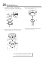
E. Prenez la portion restante de l'assemblage de
fi xation que vous aviez placé de côté. Sous l’évier
insérez le joint d’étanchéité en fi bre (voir E1), puis
la bague de montage (E2), et ensuite la bague de
montage supérieure (voir E3).
F. Maintenez les trois parties en place tout en fi xant
l'anneau de retenue (voir F1) en l'écartant et en le
plaçant dans la rainure du collet d’évier (voir F2).
G. Serrez les trois vis de fi xation fermement contre le collet
d’évier (voir G1). Évitez de trop visser.
H. Retirez l'excès de mastic à plomberie dans l’évier
avec un couteau en plastique ou un outil similaire qui
n’endommagera pas votre évier.
INSTALLATION (SUITE)
Vous avez un problème? Ne le retournez pas au magasin.
Appelez-nous sans frais au 1-833-240-6224 pour de l’assistance.
L-V 8:00am-5:00pm PST Anglais et Espagnol
La page est en cours de chargement...
La page est en cours de chargement...
La page est en cours de chargement...
La page est en cours de chargement...
La page est en cours de chargement...
La page est en cours de chargement...
La page est en cours de chargement...
La page est en cours de chargement...
La page est en cours de chargement...
La page est en cours de chargement...
La page est en cours de chargement...
La page est en cours de chargement...
La page est en cours de chargement...
La page est en cours de chargement...
La page est en cours de chargement...
La page est en cours de chargement...
La page est en cours de chargement...
La page est en cours de chargement...
La page est en cours de chargement...
La page est en cours de chargement...
La page est en cours de chargement...
La page est en cours de chargement...
La page est en cours de chargement...
-
 1
1
-
 2
2
-
 3
3
-
 4
4
-
 5
5
-
 6
6
-
 7
7
-
 8
8
-
 9
9
-
 10
10
-
 11
11
-
 12
12
-
 13
13
-
 14
14
-
 15
15
-
 16
16
-
 17
17
-
 18
18
-
 19
19
-
 20
20
-
 21
21
-
 22
22
-
 23
23
-
 24
24
-
 25
25
-
 26
26
-
 27
27
-
 28
28
-
 29
29
-
 30
30
-
 31
31
-
 32
32
-
 33
33
-
 34
34
-
 35
35
-
 36
36
-
 37
37
-
 38
38
-
 39
39
-
 40
40
-
 41
41
-
 42
42
-
 43
43


