YORKVILLE YX15PC Manuel utilisateur
- Catégorie
- Équipement musical supplémentaire
- Taper
- Manuel utilisateur

U.S.A.
Yorkville Sound Inc.
4625 Witmer Industrial Estate
Niagara Falls, New York
14305 USA
Voice: (716) 297-2920
Fax: (716) 297-3689
WORLD HEADQUARTERS
WEB ACCESS: http://www.yorkville.com
CANADA
Yorkville Sound
550 Granite Court
Pickering, Ontario
L1W-3Y8 CANADA
Voice: (905) 837-8481
Fax: (905) 837-8746
Quality and Innovation Since 1963
Printed in Canada
SERVICE MANUAL
YX15PC
TYPE: YS1107
SMT Disclaimer
Due to the complex nature of the use of SMT installed components
in Yorkville equipment, we highly caution all service technicians in
attempting to repair or replace SMT factory installed components.
Many of these components may be glued prior to initial soldering.
Replacing SMT components requires expensive
specialized de-soldering equipment and training.
Yorkville Sound will repair and replace defective SMT components
to ensure proper quality assurance and installation is maintained.
Manual-Service-YX15PC-00-1v0 • July 17, 2015

The exclamation point within an equilatereal triangle is intended to alert the
user to the presence of important operating and maintenance (servicing)
instructions in the literature accompanying the appliance.
Le point d’exclamation à l’intérieur d’un triangle équilatéral est prévu pour alerter
l’utilisateur de la présence d’instructions importantes dans la littérature accompagnant
l’appareil en ce qui concerne l’opération et la maintenance de cet appareil.
This lightning flash with arrowhead symbol, within
an equilateral triangle, is intended to alert the user to the presence of
uninsulated “dangerous voltage” within the product’s enclosure that may be
of sufficient magnitude to constitute a risk of electric shock to persons.
Ce symbole d’éclair avec tête de flèche dans un triangle équilatéral est prévu pour alerter
l’utilisateur de la présence d’un « voltage dangereux » non-isolé à proximité de l’enceinte
du produit qui pourrait être d’ampleur suffisante pour présenter un risque de choque
_safety-5v0+UL60065-00-1v0 • October 28/2014
CAUTION: TO REDUCE THE RISK OF ELECTRIC SHOCK, DO NOT REMOVE COVER (OR BACK).
NO USER SERVICEABLE PARTS INSIDE.
REFER SERVICING TO QUALIFIED SERVICE PERSONNEL.
THIS DEVICE IS FOR INDOOR USE ONLY!
Instructions pertaining to a risk of fire, electric shock, or injury to a person
Read Instructions: The Owner’s Manual should be read and understood before operation of your unit. Please, save these
instructions for future reference and heed all warnings.
Clean only with dry cloth.
Packaging: Keep the box and packaging materials, in case the unit needs to be returned for service.
Warning: To reduce the risk or fire or electric shock, do not expose this apparatus to rain or moisture. Do not
use this apparatus near water!
Warning: When using electric products, basic precautions should always be followed, including the following:
Power Sources
Your unit should be connected to a power source only of the voltage specified in the owners manual or as marked on the
unit. This unit has a polarized plug. Do not use with an extension cord or receptacle unless the plug can be fully inserted.
Precautions should be taken so that the grounding scheme on the unit is not defeated. An apparatus with CLASS I
construction shall be connected to a Mains socket outlet with a protective earthing ground. Where the MAINS plug or an
appliance coupler is used as the disconnect device, the disconnect device shall remain readily operable.
Hazards
Do not place this product on an unstable cart, stand, tripod, bracket or table. The product may fall, causing serious personal
injury and serious damage to the product. Use only with cart, stand, tripod, bracket, or table recommended by the
manufacturer or sold with the product. Follow the manufacturer’s instructions when installing the product and use mounting
accessories recommended by the manufacturer. Only use attachments/accessories specified by the manufacturer
Note: Prolonged use of headphones at a high volume may cause health damage on your ears.
The apparatus should not be exposed to dripping or splashing water; no objects filled with liquids should be
placed on the apparatus.
Terminals marked with the “lightning bolt” are hazardous live; the external wiring connected to these terminals require
installation by an instructed person or the use of ready made leads or cords.
Ensure that proper ventilation is provided around the appliance. Do not install near any heat sources such as radiators,
heat registers, stoves, or other apparatus (including amplifiers) that produce heat.
No naked flame sources, such as lighted candles, should be placed on the apparatus.
Power Cord
Do not defeat the safety purpose of the polarized or grounding-type plug. A polarized plug has two blades with one wider than the
other. A grounding type plug has two blades and a third grounding prong. The wide blade or the third prong are provided for your
safety. If the provided plug does not fit into your outlet, consult an electrician for replacement of the obsolete outlet. The AC supply
cord should be routed so that it is unlikely that it will be damaged. Protect the power cord from being walked on or pinched particularly
at plugs. If the AC supply cord is damaged DO NOT OPERATE THE UNIT. To completely disconnect this apparatus from the AC
Mains, disconnect the power supply cord plug from the AC receptacle. The mains plug of the power supply cord shall remain readily
operable.
Unplug this apparatus during lightning storms or when unused for long periods of time.
Service
The unit should be serviced only by qualified service personnel. Servicing is required when the apparatus has been damaged in
any way, such as power-supply cord or plug is damaged, liquid has been spilled or objects have fallen into the apparatus, the
apparatus has been exposed to rain or moisture, does not operate normally, or has been dropped.
AVIS: AFIN DE REDUIRE LES RISQUE DE CHOC ELECTRIQUE, N’ENLEVEZ PAS LE COUVERT
(OU LE PANNEAU ARRIERE)
NE CONTIENT AUCUNE PIECE REPARABLE PAR L’UTILISATEUR.
CONSULTEZ UN TECHNICIEN QUALIFIE POUR L’ENTRETIENT
CE PRODUIT EST POUR L’USAGE À L’INTÉREUR SEULEMENT
Instructions relatives au risque de feu, choc électrique, ou blessures aux personnes
Veuillez Lire le Manuel: Il contient des informations qui devraient êtres comprises avant l’opération de votre appareil.
Conservez. Gardez S.V.P. ces instructions pour consultations ultérieures et observez tous les avertissements.
Nettoyez seulement avec le tissu sec.
Emballage: Conservez la boite au cas ou l’appareil devait être retourner pour réparation.
Avertissement: Pour réduire le risque de feu ou la décharge électrique, n'exposez pas cet appareil à la pluie ou à l'humidité.
N’utilisez pas cet appareil près de l’eau!
Attention: Lors de l’utilisation de produits électrique, assurez-vous d’adhérer à des précautions de bases incluant celle qui suivent:
Alimentation
L’appareil ne doit être branché qu’à une source d’alimentation correspondant au voltage spécifié dans le manuel ou tel
qu’indiqué sur l’appareil. Cet appareil est équipé d’une prise d’alimentation polarisée. Ne pas utiliser cet appareil avec un
cordon de raccordement à moins qu’il soit possible d’insérer complètement les trois lames. Des précautions doivent êtres
prises afin d’eviter que le système de mise à la terre de l’appareil ne soit désengagé. Un appareil construit selon les normes
de CLASS I devrait être raccordé à une prise murale d’alimentation avec connexion intacte de mise à la masse. Lorsqu’une
prise de branchement ou un coupleur d'appareils est utilisée comme dispositif de débranchement, ce dispositif de
débranchement devra demeurer pleinement fonctionnel avec raccordement à la masse.
Risque
Ne pas placer cet appareil sur un chariot, un support, un trépied ou une table instables. L’appareil pourrait tomber et blesser
quelqu’un ou subir des dommages importants. Utiliser seulement un chariot, un support, un trépied ou une table
recommandés par le fabricant ou vendus avec le produit. Suivre les instructions du fabricant pour installer l’appareil et utiliser
les accessoires recommandés par le fabricant. Utilisez seulement les attachements/accessoires indiqués par le fabricant
Note: L'utilisation prolongée des écouteurs à un volume élevé peut avoir des conséquences néfastes sur la santé
sur vos oreilles. .
Il convient de ne pas placer sur l’appareil de sources de flammes nues, telles que des bougies allumées.
L’appeil ne doit pas être exposé à des égouttements d’eau ou des éclaboussures et qu’aucun objet rempli de liquide tel
que des vases ne doit être placé sur l’appareil.
Assurez que lappareil est fourni de la propre ventilation. Ne procédez pas à l’installation près de source de chaleur tels
que radiateurs, registre de chaleur, fours ou autres appareils (incluant les amplificateurs) qui produisent de la chaleur.
Les dispositifs marqués d’une symbole “d’éclair” sont des parties dangereuses au toucher et que les câblages
extérieurs connectés à ces dispositifs de connection extérieure doivent être effectivés par un opérateur formé ou en
utilisant des cordons déjà préparés.
Cordon d’Alimentation
Ne pas enlever le dispositif de sécurité sur la prise polarisée ou la prise avec tige de mise à la masse du cordon d’alimentation.
Une prise polarisée dispose de deux lames dont une plus large que l’autre. Une prise avec tige de mise à la masse dispose de
deux lames en plus d’une troisième tige qui connecte à la masse. La lame plus large ou la tige de mise à la masse est prévu
pour votre sécurité. La prise murale est désuète si elle n’est pas conçue pour accepter ce type de prise avec dispositif de
sécurité. Dans ce cas, contactez un électricien pour faire remplacer la prise murale. Évitez d’endommager le cordon
d’alimentation. Protégez le cordon d’alimentation. Assurez-vous qu’on ne marche pas dessus et qu’on ne le pince pas en
particulier aux prises. N’UTILISEZ PAS L’APPAREIL si le cordon d’alimentation est endommagé. Pour débrancher
complètement cet appareil de l’alimentation CA principale, déconnectez le cordon d’alimentation de la prise d’alimentation
murale. Le cordon d’alimentation du bloc d’alimentation de l’appareil doit demeurer pleinement fonctionnel.
Débranchez cet appareil durant les orages ou si inutilisé pendant de longues périodes.
Service
Consultez un technicien qualifié pour l’entretien de votre appareil. L'entretien est nécessaire quand l'appareil a été endommagé de
quelque façon que se soit. Par exemple si le cordon d’alimentation ou la prise du cordon sont endommagés, si il y a eu du liquide
qui a été renversé à l’intérieur ou des objets sont tombés dans l'appareil, si l'appareil a été exposé à la pluie ou à l'humidité, si il ne
fonctionne pas normalement, ou a été échappé.
S2125A
Caution: hot surface
Attention: surface chaude
IEC 60417-5041
IMPORTANT SAFETY INSTRUCTIONS
IMPORTANT SAFETY INSTRUCTIONS (UL60065)
FOLLOW ALL INSTRUCTIONS SUIVEZ TOUTES LES INSTRUCTIONS
The Lightning Flash with arrowhead symbol within an equilateral triangle, is intended to alert the user to the presence of uninsulated
"dangerous voltage" within the product enclosure that may be of sufficient magnitude to constitute a risk of shock to persons
The exclamation point within an equilateral triangle is intended to alert the user to the presence of important operating and maintenance
(servicing) instructions in the literature accompanying the product
1. Read these instructions.
2. Keep these instructions.
3. Heed all warnings.
4. Follow all instructions.
5. Do not use this apparatus near water.
6. Clean only with dry cloth.
7. Do not block any ventilation openings. Install in accordance with the manufacturer’s instructions.
8. Do not install near any heat sources such as radiators, heat registers, stoves, or other apparatus (including amplifiers) that produce heat.
9. Do not defeat the safety purpose of the polarized or grounding-type plug. A polarized plug has two blades with one wider than the other. A
grounding type plug has two blades and a third grounding prong. The wide blade or the third prongs are provided for your safety. If the provided
plug does not fit into your outlet, consult an electrician for replacement of the obsolete outlet.
10. Protect the power cord from being walked on or pinched particularly at plugs, convenience receptacles, and the point where they exit
from the apparatus.
11. Only use attachments/accessories specified by the manufacturer.
12. Use only with the cart, stand, tripod, bracket, or table specified by the manufacturer, or sold with the apparatus. When a cart is used, use caution
when moving the cart/apparatus combination to avoid injury from tip-over.
13. Unplug this apparatus during lightning storms or when unused for long periods of time.
14. Refer all servicing to qualified service personnel. Servicing is required when the apparatus has been damaged in any way, such as
power-supply cord or plug is damaged, liquid has been spilled or objects have fallen into the apparatus, the apparatus has been exposed to rain or
moisture, does not operate normally, or has been dropped.
WARNING:
• To reduce the risk of fire or electric shock, do not expose this apparatus to rain or moisture and objects filled with liquids, such as vases, should not be
placed on this apparatus.
• To completely disconnect this apparatus from the ac mains, disconnect the power supply cord plug from the ac receptacle.
• The mains plug of the power supply cord or appliance coupler shall remain readily accessible.
Le symbole représentant un éclair avec une flèche à l’intérieur d’un triangle équilatéral est utilisé pour prévenir l’utilisateur de la
présence d’une tension électrique dangereuse non isolée à l’intérieur de l’appareil. Cette tension est d’un niveau suffisamment
élevé pour représenter un risque d’électrocution
Le symbole représentant un point d’exclamation à l’intérieur d’un triangle équilatéral, signale à l’utilisateur la présence d’instructions
importantes relatives au fonctionnement et à l’entretien de l’appareil dans cette notice d’installation
1. Lisez ces instructions.
2. Conservez ces instructions.
3. Respecter tous les avertissements.
4. Suivez toutes les instructions.
5. N'utilisez pas l'appareil près de l'eau.
6. Nettoyer uniquement avec chiffon sec.
7. Ne bloquez pas les ouvertures de ventilation. Installer en suivant les instructions du fabricant.
8. Ne pas installer près des sources de chaleur telles que radiateurs, bouches de chaleur, four ou autres appareils (y compris les amplificateurs)
produisant de la chaleur.
9. N'annulez pas l'objectif sécuritaire de la fiche polarisée ou de la tige de mise à la terre. Une fiche polarisée possède deux lames avec une plus
large que l'autre. Une prise avec mise à la terre possède deux lames et une troisième tige. La lame large ou la troisième tige sont fournis pour
votre sécurité. Si la fiche n'entre pas dans votre prise, consultez un électricien pour remplacer la prise obsolète.
10. Protéger le cordon d'alimentation des piétinements ou pincements en particulier près des fiches, des prises de courant et au point de
sortie de l'appareil.
11. Utilisez uniquement les accessoires spécifiés par le fabricant.
12. Utiliser uniquement avec un charriot, stand, trépied ou une table spécifiée par le fabricant, ou vendus avec l'appareil.
13. Débranchez l'appareil durant un orage ou lorsqu'il reste inutilisé pendant de longues périodes de temps.
14. Confiez toute réparation à un technicien qualifié. Une réparation est nécessaire lorsque l'appareil a été endommagé de quelque façon que ce
soit; comme lorsque le cordon d'alimentation ou la fiche est endommagé, lorsque du liquide a été renversé ou des objets sont tombés à l'intérieur,
lorsque l'appareil a été exposé à la pluie ou l'humidité, ne fonctionne pas normalement, ou est tombé.
AVERTISSEMENT:
• Pour réduire les risques d'incendie ou de choc électrique, ne pas exposer cet appareil à la pluie ou à l'humidité et ne placez pas d’objets contenant
des liquides, tels que des vases, sur l’appareil.
• Pour isoler totalement cet appareil de l'alimentation secteur, débranchez totalement son cordon d'alimentation du réceptacle CA.
• La prise du cordon d’alimentation ou du prolongateur, si vous en utilisez un comme dispositif de débranchement, doit rester facilement accessible
CAUTION
TO PREVENT ELECTRIC SHOCK HAZARD,
DO NOT CONNECT TO MAINS POWER SUPPLY
WHILE GRILLE IS REMOVED.
AVIS
POUR PRÉVENIR LES RISQUES D'ÉLECTROCUTION,
NE PAS RACCORDER A L’ALIMENTATION ÉLECTRIQUE ALORS
QUE LA GRILLE EST RETIRÉE.

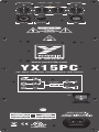
LINE IN LEVEL POWER
POWER
ON
LIMIT CLIP
LINE IN LINK OUT
TYPE: YS1107
A-Z1474 / 1v1
MIC LEVEL
MIC
FUSE: 3.15A L 250V sloblo
100-240 V~ 50/60Hz
250W MAX
FUSE: 3.15A L 250V sloblo
120 VAC 60Hz
250W MAX
Designed & Manufactured by
YORKVILLE SOUND • TORONTO, CANADA
BASS TREBLE
+
-
300 WATT POWERED LOUDSPEAKER ENCLOSURE
YX SERIES
YX15PC
www.yorkville.com
MaxMin
0
0
+
-
0
MaxMin
0
+24 PHANTOM
1
3
2
1
3
2
2
3
1
MIC IN
MIC
GAIN
LINE IN
LINK OUT
LEVEL
Bass Treble
250 WATTS
TONE CONTROLS
50 WATTS
30hz/5kHz
5kHz
LR1004

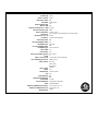
Specification
s
System Type
2-Way
Active or Passive
Active
Peak Power (watts)
600
Biampable
Self Powered
Biamp Operation Only
Yes
Max SPL (dB)
125
Frequency Response (Hz +/- 3db)
55 - 26k
Crossover Frequency (Hz)
4000
Driver Configuration
15 inch / 1 inch
HF Driver(s)
1 inch Throat, Ceramic Magnet, 1.4 inch PETP Film
HF Dispersion (°H x °V)
80 x 50
LF Driver(s)
15 inch Ceramic Magnet
Total Power (watts)
300
HF Power Amplifier (watts)
50
HF Amplifier Type
Class A/B
LF Power Amplifier (watts)
250
LF Amplifier Type
Two Tier Class H
Power Cable
Yes
Power Switch
Yes
Power Consumption (typ/max)
120 / 310 Va
Inputs
2
Inputs - 1/4-inch Jacks
1 Line / 1 Mic (XLR Combi jacks)
Input Sensitivity (Vrms Sine)
+4dBv / 1.23V
Mixer Controls
Mic Gain
Line In Gain
Bass/Treble
Level Controls
Line/Mic
Limiter
Yes
LED Indicators
Power,Limit,Clip
Feet
Yes
Flying Hardware
N/A
Optional Flying Hardware
N/A
Bar Handles
2 (Side)
Enclosure Materials
All Plywood Construction
Grille
Perforated Metal
Dimensions (DWH xbackW, inches)
15.5 x 19.25 x 27 x 7.5
Dimensions (DWH xbackW, cm)
39 x 49 x 69 x 19
Weight (lbs/kg)
44/19.9

YX15PC PARTS Parts List 7/17/2015
YS # Description Qty. YS # Description Qty. YS # Description Qty.
5203 _47P 100V 2%CAP T&R RAD CER.2NPO 1
5206 __1N 400V 5%CAP T&R RAD .2FLM 2
5208 __2N2 400V 5%CAP T&R RAD .2FLM 3
6451 __4N7 250V 20%CAP BLK 'Y' 10MM AC 1
5204 _10N 100V 10%CAP T&R RAD .2FLM 2
5205 _15N 100V 10%CAP T&R RAD .2FLM 1
5840 _22N 400V 10%CAP BLK RAD POLY FLM 2
5224 _47N 100V 10%CAP T&R RAD .2FLM 2
5882 220N 250VDC 10%CAP BLK RAD PLY FLM 1
5233 330N 63V 5%CAP T&R RAD .2FLM 3
5266 680N 250V 20%CAP BLK 'X2' 27MM AC 1
5254 __1U 63V 20%CAP T&R 4X7MM .2EL 5
5257 __2U2 63V 20%CAP T&R RAD .2EL 2
5959 _10U 450V 20%CAP BLK EL 11
5631 _22U 50V 20%CAP T&R 6X7MM .2EL 5
5879 100U 16V 20%CAP T&R 8X7MM .2EL 2
5630 330U 25V 20%CAP BLK 10X13MM EL 4
5616 3300U 50V 20%CAP BLK 18X35MM EL 4
4434 _10K B LIN 9MM DETENT P32 3
4435 _50K B LIN 9MM DETENT P32 1
4520 _10K TRIM POT 2
6405 RED 3MM LED 2V1 20MA DIFFUSD 1
6400 YEL 3MM LED 2V1 20MA DIFFUSD 1
6408 GRN 3MM LED 2V2 20MA DIFFUSD 1
6438 1N4007 1000V 1A0 DIODE T&R 7
6934 MR854 400V 3A0 DIODE FASREC 4
6875 1N5359B 24V0 5W0 ZENER 5% T&R 2
6854 2N6517 TO92 NPN TRAN TA 2
6812 2SB1647 TO3P PNP TRAN DARL 4
6932 IRFP9140N TO247 PCH MFET TM 2
6619 _10K 5% THERMISTOR VISH NTC 1
4090 1/4IN &XLR PCB MT VERT COMBO NCJ6-
V
1
4140 XLR MALE PCB MT VERT 24MM A-SERIE
S
2
3543 16 PIN BREAKAWAY RA 90 LOCK .156 0.25
4149 5 PIN POWER PIN HEADER MALE R
A
1
4150 6 PIN POWER PIN HEADER MALE R
A
1
4597 22AWG STRAN TC WIR T&R JMP 18
4748 2W00 3R9 5% T&R RES 2
4921 W250 100R 5% .2INU T&R RES 1
4137 RELAY 2C 16AMP DC110 033MA PC 1
8656 1/4X.171 NYLON SPACER 8
9067 1/8X5/16XID.64 NYLON SPACER 4
4007 .9 LED CUSTOM SPACER 3
3601 RING TERMINAL 16AWG WIRE & #8 SCREW 8
3070 PATCH 04 18AWG NX55P TWISTPAIR 1
8604 10-32 T NUT 10
2475 T3,15ALGDC BUSSMANN 5X20MM FUSE 1
3719 DUAL XSISTOR SPRING, ZINC CLEA
R
3
3810 4" NYLON CABLE TIE 3
8653 LOW PROFILE POINTER AT 12 KNOB 4
3426 8' 3/16 SJT AC LINE CORD REMOVB-CS
A
1
4125 ELASTOMER PAD - 2-TO218 1X2.050 3
8581 CUSTOM PBL TRANSISTOR SPACE
R
3
4184 DPST ROKR SW QUIK 250" AC/PWR IEC6 1
CH1425
U
XFMR:NX25P-2/NX300P/YX15PC/NX10C 1
8570 CORNER,2 LEGS NOTCED BLACK POWDER C 15
8565 BAR HANDLE ALL METAL RECTANGULA
R
2
7567 _8R 50W 1.00" HF DRIVER BOLT ON 1
9000
A
DAPTOR FLANGE FOR HORN 1
HRN00
3
HORN 129.4 X 317.5 X 196.5MM 1
8240D LOGO YORKVILLE SMALL BLUE DOMED 1
8489 1/4-20 SPLIT WASHER BLACK OXIDE 2
8387 PS NEO SC41 1/16" X 0.5" X 100' ROL 3

YX15PC Parts Reference List 7/17/2015
RE
F
YS # Description RE
F
YS # Description RE
F
YS # Description
A
I-ASS M1538-59 YX15PC POWER AMP, SUPPLY, INPUT P
C
K1 4137 RELAY 2C 16AMP DC110 033MA PC
C1 5879 100U 16V 20%CAP T&R 8X7MM .2E
L
LD1 6408 GRN 3MM LED 2V2 20MA DIFFUS
D
C2 5282 _10U 16V 20%CAP T&R 5X7MM .2N
P
LD2 6400 YEL 3MM LED 2V1 20MA DIFFUS
D
C3 5879 100U 16V 20%CAP T&R 8X7MM .2E
L
LD3 6405 RED 3MM LED 2V1 20MA DIFFUS
D
C4 5206 __1N 400V 5%CAP T&R RAD .2FLM P1 4434 _10K B LIN 9MM DETENT P3
2
C5 5224 _47N 100V 10%CAP T&R RAD .2FLM P2 4434 _10K B LIN 9MM DETENT P3
2
C6 5282 _10U 16V 20%CAP T&R 5X7MM .2N
P
P3 4435 _50K B LIN 9MM DETENT P3
2
C7 5282 _10U 16V 20%CAP T&R 5X7MM .2N
P
P4 4432 _10K B LIN 9MM P3
2
C8 5631 _22U 50V 20%CAP T&R 6X7MM .2E
L
P5 4520 _10K TRIM PO
T
C9 5203 _47P 100V 2%CAP T&R RAD CER.2NPO P6 4520 _10K TRIM PO
T
C10 5631 _22U 50V 20%CAP T&R 6X7MM .2E
L
PCB1 M1538BLANK 2_OZ 2SD 119.19SQIN 02PER YX15P
C
C11 5631 _22U 50V 20%CAP T&R 6X7MM .2E
L
Q3 6932 IRFP9140N TO247 PCH MFET T
M
C12 5282 _10U 16V 20%CAP T&R 5X7MM .2N
P
Q4 6805 2SD2560 TO3P NPN TRAN DAR
L
C13 5631 _22U 50V 20%CAP T&R 6X7MM .2E
L
Q5 6812 2SB1647 TO3P PNP TRAN DAR
L
C14 5945 _10U 63V 20%CAP T&R RAD .2EL Q6 6812 2SB1647 TO3P PNP TRAN DAR
L
C15 5282 _10U 16V 20%CAP T&R 5X7MM .2N
P
Q7 6805 2SD2560 TO3P NPN TRAN DAR
L
C16 5631 _22U 50V 20%CAP T&R 6X7MM .2E
L
Q8 6931 IRFP140N TO247 NCH MFET T
M
C17 5233 330N 63V 5%CAP T&R RAD .2FLM Q9 6854 2N6517 TO92 NPN TRAN T
A
C18 5233 330N 63V 5%CAP T&R RAD .2FLM Q10 6854 2N6517 TO92 NPN TRAN T
A
C19 5208 __2N2 400V 5%CAP T&R RAD .2FLM R1 4748 2W00 3R9 5% T&R RES
C20 5233 330N 63V 5%CAP T&R RAD .2FLM R2 4748 2W00 3R9 5% T&R RES
C21 5208 __2N2 400V 5%CAP T&R RAD .2FLM R18 4921 W250 100R 5% .2INU T&R RES
C22 5206 __1N 400V 5%CAP T&R RAD .2FLM R36A 6619 _10K 5% THERMISTOR VISH NT
C
C23 5208 __2N2 400V 5%CAP T&R RAD .2FLM W1 3543 16 PIN BREAKAWAY RA 90 LOCK .156
C24 5840 _22N 400V 10%CAP BLK RAD POLY FLM W4 4150 6 PIN POWER PIN HEADER MALE R
A
C25 5282 _10U 16V 20%CAP T&R 5X7MM .2N
P
W5 4149 5 PIN POWER PIN HEADER MALE R
A
C26 5630 330U 25V 20%CAP BLK 10X13MM EL X1 4597 22AWG STRAN TC WIR T&R JM
P
C27 5630 330U 25V 20%CAP BLK 10X13MM EL X2 4597 22AWG STRAN TC WIR T&R JM
P
C28 5840 _22N 400V 10%CAP BLK RAD POLY FLM X3 4597 22AWG STRAN TC WIR T&R JM
P
C31 5282 _10U 16V 20%CAP T&R 5X7MM .2N
P
X4 4597 22AWG STRAN TC WIR T&R JM
P
C32 5630 330U 25V 20%CAP BLK 10X13MM EL X5 4597 22AWG STRAN TC WIR T&R JM
P
C33 5282 _10U 16V 20%CAP T&R 5X7MM .2N
P
X6 4597 22AWG STRAN TC WIR T&R JM
P
C34 5630 330U 25V 20%CAP BLK 10X13MM EL X7 4597 22AWG STRAN TC WIR T&R JM
P
C35 5616 3300U 50V 20%CAP BLK 18X35MM EL X8 4597 22AWG STRAN TC WIR T&R JM
P
C36 5616 3300U 50V 20%CAP BLK 18X35MM EL X9 4597 22AWG STRAN TC WIR T&R JM
P
C37 5945 _10U 63V 20%CAP T&R RAD .2EL X10 4597 22AWG STRAN TC WIR T&R JM
P
C38 5959 _10U 450V 20%CAP BLK EL X11 4597 22AWG STRAN TC WIR T&R JM
P
C39 5616 3300U 50V 20%CAP BLK 18X35MM EL X12 4597 22AWG STRAN TC WIR T&R JM
P
C40 5882 220N 250VDC 10%CAP BLK RAD PLY FLM X19 4597 22AWG STRAN TC WIR T&R JM
P
C41 5616 3300U 50V 20%CAP BLK 18X35MM EL X20 4597 22AWG STRAN TC WIR T&R JM
P
C42 6451 __4N7 250V 20%CAP BLK 'Y' 10MM AC X21 4597 22AWG STRAN TC WIR T&R JM
P
C43 5266 680N 250V 20%CAP BLK 'X2' 27MM AC X22 4597 22AWG STRAN TC WIR T&R JM
P
C10A 5254 __1U 63V 20%CAP T&R 4X7MM .2E
L
X23 4597 22AWG STRAN TC WIR T&R JM
P
C1A 5205 _15N 100V 10%CAP T&R RAD .2FLM X24 4597 22AWG STRAN TC WIR T&R JM
P
C20A 5257 __2U2 63V 20%CAP T&R RAD .2EL ZD1 6875 1N5359B 24V0 5W0 ZENER 5% T&R
C23A 5254 __1U 63V 20%CAP T&R 4X7MM .2E
L
ZD2 6875 1N5359B 24V0 5W0 ZENER 5% T&R
C24A 5254 __1U 63V 20%CAP T&R 4X7MM .2E
L
C2A 5224 _47N 100V 10%CAP T&R RAD .2FLM
C3A 5204 _10N 100V 10%CAP T&R RAD .2FLM
C5B 5254 __1U 63V 20%CAP T&R 4X7MM .2E
L
C6A 5204 _10N 100V 10%CAP T&R RAD .2FLM
C6B 5257 __2U2 63V 20%CAP T&R RAD .2EL
C9A 5254 __1U 63V 20%CAP T&R 4X7MM .2E
L
D1 6934 MR854 400V 3A0 DIODE FASRE
C
D2 6934 MR854 400V 3A0 DIODE FASRE
C
D3 6934 MR854 400V 3A0 DIODE FASRE
C
D4 6934 MR854 400V 3A0 DIODE FASRE
C
D5 6438 1N4007 1000V 1A0 DIODE T&
R
D6 6438 1N4007 1000V 1A0 DIODE T&
R
D7 6438 1N4007 1000V 1A0 DIODE T&
R
D8 6438 1N4007 1000V 1A0 DIODE T&
R
D9 6438 1N4007 1000V 1A0 DIODE T&
R
HW1 4007 .9 LED CUSTOM SPACE
R
HW10 8656 1/4X.171 NYLON SPACE
R
HW11 8656 1/4X.171 NYLON SPACE
R
HW12 8656 1/4X.171 NYLON SPACE
R
HW13 8656 1/4X.171 NYLON SPACE
R
HW14 8656 1/4X.171 NYLON SPACE
R
HW15 8656 1/4X.171 NYLON SPACE
R
HW2 4007 .9 LED CUSTOM SPACE
R
HW3 4007 .9 LED CUSTOM SPACE
R
HW4 8656 1/4X.171 NYLON SPACE
R
HW5 8656 1/4X.171 NYLON SPACE
R
HW6 8656 1/4X.171 NYLON SPACE
R
HW7 8656 1/4X.171 NYLON SPACE
R
HW8 8656 1/4X.171 NYLON SPACE
R
HW9 8656 1/4X.171 NYLON SPACE
R
J1 4090 1/4IN &XLR PCB MT VERT COMBO NCJ6-
V
J2 4010 XLR FEML PCB MT VERT 24MM AA-SERIE
S
J3 4140 XLR MALE PCB MT VERT 24MM A-SERIE
S

+24 PHANTOM
1
3
2
1
3
2
2
3
1
MIC IN
MIC
GAIN
LINE IN
LINK OUT
LEVEL
Bass Treble
250 WATTS
TONE CONTROLS
50 WATTS
30hz/5kHz
5kHz

1
1
2
2
3
3
4
4
5
5
6
6
7
7
8
8
9
9
10
10
11
11
12
12
13
13
14
14
15
15
16
16
17
17
K K
J J
I I
H H
G G
F F
E E
D D
C C
B B
A A
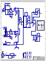
Product(s):
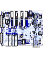
M1538 1 4Sheet OfPCB#: Rev#: V03
250W Powered SpeakerDescription:
YX15PC
Yorkville Sound Ltd.
550 Granite Court
Pickering, ON
Canada L1W 3Y8
www.yorkville.com
EML Rev#: 03
Input.SchDocModified: File:28/11/2014 Tmp Rev: V23
WFR
400V
2N2
RAD .2in
C19
400V
2N2
RAD .2in
C23
63V
330N
RAD .2in
C17
63V
330N
RAD .2in
C18
TWTR
CDSF4148
D1005
D15
W100
0805
100K0
R7
W100
0805
10K0
R40
W100
0805
10K0
R39
Mic In
XLR FEML
4010
J2
CDSF4148
D1005
D12
W125
0805
18K00
R6
W100
10K0
0805
R63
400V
1N
RAD .2in
C22
Link
4140
Male XLR
J3
25V100N
0805
C44
W100
0805
100K0
R56
W125
0805
562R0
R16
50V
1N
0805
C46
W125
0805
562R0
R17
CDSF4148
D1005
D18
W100
0805
4K99
R10
W100
0805
4K99
R15
16V
10U
C7
1/4W
100R
R18
16V
100U
C1
W125
0805
150K
R9
100V
82N
0805
C47
MMBTA14LTIG
Q11
50V
1N
0805
C45
RED
Clip LED
6405
LD3
63V
330N
C20
400V
2N2
RAD .2in
C21
CDSF4148
D1005
D11
W125
0805
1K800
R5
W100
2K74
0805
R57
W125
33K
0805
R5A
W125
33K
0805
R60
MC33079D
10
9
8
+
-
U6C
W100
0805
10K0
R49
W100
9K09
0805
R58
W100
0805
499R
R24
W100
0805
499R
R25
16V
10U
C12
100V82N
0805
C48
MC33078D
3
2
1
-
+
U3A
MC33079D
12
13
14
+
-
U6D
MC33079D
5
6
7
+
-
U6B
MC33078D
5
6
7
-
+
U3B
M
10K
B
MIC LEVEL
4432
T B
P4A
4090
XLR-PHONE
Line In
X3
SH
X2
X1
+1/4
J1A
MC33078D
3
2
1
-
+
U4A
W100
0805
1K0
R38
W100
0805
1K0
R37
W100
0805
10K0
R22
W100
0805
10K0
R21
W100
0805
10K0
R32
W100
0805
10K0
R31
50V
1N
0805
C49
50V
1N
0805
C50
16V
10U
C2
MC33078D
5
6
7
-
+
U4B
W125
0805
1K21
R13
M
10K
B
LINE LEVEL
4434
T B
P1A
4090
XLR-PHONE
Line In
T
R
S
S
T
R
J1B
16V
100U
C3
W125
0805
150K
R14
MC33078D
5
6
7
-
+
U5B
W100
0805
10K0
R8
W100
0805
10K0
R19
W100
0805
10K0
R33
W250
1206
619R0
R26
W250
1206
619R0
R28
50V
22U
C8
50V
22U
C11
50V
22U
C10
W125
4K7
0805
R12
W125
1K21
0805
R11
W125
47K5
0805
R20
W125
1K21
0805
R36
W125
4K7
0805
R23
W100
475K
0805
R34
16V
10U
C6
400V
1N
RAD .2in
C4
100V
47N
RAD .2in
C5
100V
47P
C9
MC33078D
3
2
1
-
+
U5A
M
B
10K
TREBLE
4434
T B
P2A
M
B
50K
BASS
4435
T B
P3A
CDSF4148
D1005
D14
CDSF4148
D1005
D10
CDSF4148
D1005
D13
CLIP
CLIP
CLIP
CLIP
CLIP
MC33079D
3
2
1
+
-
U6A
1N5359B
24V0
5W0
ZD2
1N5359B
24V0
5W0
ZD1
W250
100R
1206
R47
W250
1206
619R0
R27
W250
1206
619R0
R29
1K0
W100
0805
R30
W100
0805
10K0
R55
W100
0805
10K0
R52
W100
0805
10K0
R43
W125
0805
681R
R48
W125
0805
681R
R35
50V
22U
C16
50V
22U
C13
W100
0805
10K0
R42
W125
4K7
0805
R1A
100V
15N
C1A
W100
15K0
0805
R2A
100V
47N
RAD .2in
C2A
W100
10K0
0805
R3A
100V
10N
RAD .2in
C3A
W125
33K
0805
R59
TP8
TP9
W125
0805
3K32
R43A
W100
0805
10K0
R55A
180P
0805
50V
C3B
180P
0805
50V
C4B
180P
0805
50V
C1B
180P
0805
50V
C2B
+15V
CROSSOVER RESPONSE
IG
IG
IG
IG
IG
IG
IG
IG
MC33078D
84
V+
V-
U3C
MC33079D
411
V+
V-
U6E
MC33078D
84
V+
V-
U5C
MC33078D
84
V+
V-
U4C
+15V
-15V
+15V
-15V
+15V
-15V
+15V
-15V
-12dB/Oct
-18dB/Oct
65Hz 5kHz
+24V
GND2
GND2
GND2
GND2
GND2
GND2
GND2
GND2
GND2
GND2
GND2
GND2
GND2
GND2
N1
N2
N6
N12
N11
N10
N7
N8
N9
N13
N14
N15

1
1
2
2
3
3
4
4
5
5
6
6
7
7
8
8
9
9
10
10
11
11
12
12
13
13
14
14
15
15
16
16
17
17
K K
J J
I I
H H
G G
F F
E E
D D
C C
B B
A A
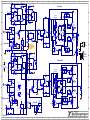
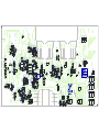
Power Amp
Section:
Product(s):
Power_Amp.SCHDOC
M1538 2 5Sheet OfPCB#: Rev#:
Modified:
V03
File:28/11/2014
YX15PC
EML Rev#: 03
Tmp Rev: V23
Limit LED
YEL
6400
LD2
NET00250
NET00251 NET00135
NET00134
NET00133
NET00127
NET00037
NET00036
NET00072
NET00074
NET00079
NET00084
NET00058
NET00081
NET00056
NET00092
NET00057
NET00011
NET00006
NET00008
NET00005
NET00004
NET00009
NET00007
TWTR
NET00003
W100
10K0
0805
R121
W100
475K
0805
R75
W100
475K
0805
R66
W125
4K7
0805
R100
WFR
W100
0805
18K2
R87
50V100P
0805
C54
100V47P
0805
C51
W125
0805
10R0
R50
D35
BAS21L
W333
1210
33R
R53
W500
2010
2K2
R82
50V5N6
0805
C63
4
3
W1C
4
1
W1A
W100
0805
10M
R70
W100
0805
15K0
R72
CDSF4148
D1005
D32
W100
0805
18K2
R88
W100
0805
18K2
R96
W100
0805
100R
R78
W100
0805
100R
R81
W100
0805
15K0
R77
W100
0805
100R
R80
W125
2K2
0805
R117
MMBT3906LT1
Q2
MMBT3906LT1
Q1
50V
4N7
0805
C56
W125
2K2
0805
R54
W100
10K0
0805
R62
50V330P
0805
C62
W100
0805
1K0
R114
100V47P
0805
C64
MC33078D
3
2
1
-
+
U13A
W100
0805
1K0
R51
MC33078D
3
2
1
-
+
U7A
W100
0805
2K74
R44
25V
100N
0805
C69
W125
0805
47R
R131
25V
100N
0805
C60
W125
0805
47R
R45
W100
15K0
0805
R130
100V
2N7
0805
C66
W100
15K0
0805
R126
W125
0805
10R0
R122
W100
15K0
0805
R103
W125
0805
47R
R84
100V
2N7
0805
C53
100V
2N7
0805
C55
W100
15K0
0805
R104
W100
27K4
0805
R109
W500
2010
2K2
R108
25V
330U
C34
W333
1210
33R
R128
W500
2010
2K2
R140
D42
W500
2010
2K2
R86
25V330U
C26
0W35
16V0
ZD5
W125
0805
47R
R119
1W00
0R047
2512
R112
1W00
0R047
2512
R135
50V5N6
0805
C72
0W35
16V0
ZD8
50V5N6
0805
C58
NET00091
W125
0805
47R
R93
MR854
D1
2.0W
3R9
R2
4
4
W1D
4
2
W1B
2.0W
3R9
R1
BIAS
1512
+
14
-
13
16
U9B
LM13700MX
7828
V+
11
V-
6
W100
0805
10M
R73
W100
0805
100R
R79
16V
10U
5X7MM .2in
C33
100V
100N
1206
C57
16V
10U
C15
W100
0805
2K74
R118
100V
2N7
0805
C67
W125
0805
10R0
R129
W100
27K4
0805
R125
W125
0805
10R0
R64
25V
330U
C32
W333
1210
33R
R124
25V330U
C27
W333
1210
33R
R61
W125
0805
47R
R134
50V5N6
0805
C59
W125
0805
47R
R99
MR854
D4
400V
22N
C28
400V
22N
C24
50V180P
0805
C29
CDSF4148
D1005
D33
16V
10U
C25
16V
10U
5X7MM .2in
C31
50V1N
0805
C61
W063
0603
47K
R101
W100
0805
18K2
R95
MC33079D
12
13
14
+
-
U12D
W063
0603
47K
R102
50V180P
0805
C30
LM13700MX
7828
BIAS
25
+
3
-
4
1
U9A
MC33079D
3
2
1
+
-
U12A
50V1N
0805
C52
W100
0805
100R
R105
0W2
12V0
ZD7
84
V+
V-
U13C
0W2
15V0
ZD6
MMBTA64LTIG
Q17
D41
BAS21L
W100
0805
100R
R138
D24
BAS21L
MC33078D
5
6
7
-
+
U7B
0W2
10V0
ZD4
0W2
10V0
ZD3
MMBTA64LTIG
Q13
84
V+
V-
U7C
D23
BAS21L
MR854
D2
MR854
D3
1W00
0R047
2512
R97
1W00
0R047
2512
R98
W100
0805
15K0
R113
W100
0805
15K0
R76
W125
4K7
0805
R94
W100
0805
15K0
R71
W100
0805
15K0
R46
W125
0805
47R
R132
D36
BAS21L
W125
470R
0805
R127
M
Lin
10K
Woofer Bias
TB
P6
4520
MC33078D
5
6
7
-
+
U13B
W125
470R
0805
R106
M
Lin
10K
Horn Bias
TB
P5
4520
2SB1647
TO3P
6812
Q6
2SD2560
TO3P
6805
Q7
2SD2560
6805
Q4A
2SB1647
6812
Q5A
IRFP140N
N
TO247
6931
G
D
S
Q8A
P
IRFP9140N
TO247
6932
D S
G
Q3A
NET00001
NET00013
NET00014
NET00015
NET00016NET00017
NET00019
NET00020
NET00022
NET00023
NET00026
NET00032
NET00033
NET00034
NET00035
NET00039
NET00047
NET00048
NET00049
NET00061
NET00062
NET00064NET00065
NET00066
NET00067
NET00069
NET00070
NET00071
NET00073
NET00080
NET00112
NET00114
NET00116
NET00117
NET00118
NET00120 NET00122
NET00128
NET00129 NET00131
W100
0805
10M
R68
W100
0805
10M
R67
W500
2010
2K2
R89
W500
2010
2K2
R90
W500
2010
2K2
R83
W500
2010
2K2
R85
W500
2010
2K2
R91
W500
2010
2K2
R92
W500
2010
2K2
R137
W500
2010
2K2
R136
W500
2010
2K2
R139
W500
2010
2K2
R107
W500
2010
2K2
R110
W500
2010
2K2
R111
GND
GND
W100
0805
2K0
R4
YS# 7527
HORN
YS# 7564
WOOFER
+15V
CDSF4148
D1005
D31A
CDSF4148
D1005
D30A
MC33079D
10
9
8
+
-
U12C
MMBT3906LT1
Q1A
MMBT3904
Q3A
MMBT3904
Q4A
MMBT3904
Q2A
CDSF4148
D1005
D1A
CDSF4148
D1005
D2A
CDSF4148
D1005
D3A
CDSF4148
D1005
D4A
W100
2K74
0805
R6A
W100
1K0
0805
R7A
W100
1K0
0805
R8A
W125
8K25
0805
R9A
W125
47K5
0805
R10A
W100
2K0
0805
R13A
W125
47K5
0805
R11A
W100
2K0
0805
R12A
W100
2K74
0805
R14A
W100
2K74
0805
R15A
W125
47K5
0805
R16A
W125
47K5
0805
R17A
100V
10N
RAD .2in
C6A
50V100P
0805
C8A
50V100P
0805
C7A
63V
1U
C10A
63V
1U
C9A
MC33079D
5
6
7
+
-
U12B
MMBT3906LT1
Q20A
MMBT3904
Q22A
MMBT3904
7838
Q23A
MMBT3904
Q21A
CDSF4148
D1005
D20A
CDSF4148
D1005
D21A
CDSF4148
D1005
D22A
CDSF4148
D1005
D23A
W125
4K7
0805
R20A
W100
1K0
0805
R22A
W100
1K0
0805
R21A
W100
10K0
0805
R23A
W125
47K5
0805
R37A
W100
2K0
0805
R25A
W125
47K5
0805
R26A
W100
2K0
0805
R27A
W100
10K0
0805
R29A
W100
10K0
0805
R28A
W125
82K5
0805
R30A
W125
82K5
0805
R31A
63V
2U2
C20A
50V100P
0805
C22A
50V100P
0805
C21A
63V
1U
C23A
63V
1U
C24A
CDSF4148
D1005
D32A
MMBT3906LT1
Q25A
MMBT3904
7838
Q24A
W125
470R
0805
R32A
W100
4K99
0805
R33A
W100
1K0
0805
R35A
W125
750R
0805
R34A
0W2
10V0
ZD1A
CDSF4148
D1005
D33A
MMBT3904
Q5A
W125
470R
0805
R18A
W100
4K99
0805
R19A
10K
NTC
R36A
6619
W100
1K0
0805
R10B
W100
1K0
0805
R11B
MMBF4391LT1
S
D
Q2B
MMBF4391LT1
S
D
Q1B
CDSF4148
D1005
D1B
CDSF4148
D1005
D2B
W125
0805
2K2
R4B
0W2
18V0
ZD1B
GND
63V
1U
C5B
W100
0805
10K0
R12B
W125
0805
1M
R13B
CDSF4148
D1005
D3B
63V
2U2
C6B
MUTE
MUTE
50V10N
0805
C15B
RED
RED_
NET00160
+34V
+34V
+34V
-34V
-34V
-34V
+80V
+80V
-80V
-80V
+15V
-15V
+15V
-15V
+15V
+15V
+15V
+15V
Horn Amp
Woofer Amp
Mute Off
Woofer Limiter
Horn Limiter
Set to 1.5mV
Set to 1.5mV
MC33079D
7668
411
V+
V-
U12E
+15V
-15V
1/8W
36K0
R65
1/8W
37K4
R120
+14V
52Vac
40W / 8R
300W / 8R
THERMALLY COUPLED
TO CHASSIS AT STANDOFF.
ADD THERMAL COMPOUND
BETWEEN THERMISTOR
AND STANDOFF.
BIAS+
BIAS-
BIAS+
BIAS-
GND2
GND2
GND2
GND2
GND2
GND2
GND2
GND2
GND2
GND2
GND2
GND2
GND2
LM13700MX
Dual VCA
7828
8
7
(VCC)
U9C
LM13700MX
Dual VCA
7828
9
10
(VCC)
U9D
N5

1
1
2
2
3
3
4
4
5
5
6
6
7
7
8
8
9
9
10
10
11
11
12
12
13
13
14
14
15
15
16
16
17
17
K K
J J
I I
H H
G G
F F
E E
D D
C C
B B
A A
Power Supply
Section:
Product(s):
Power_Supply.SchDoc
M1538 3 5Sheet OfPCB#: Rev#:
Modified:
V03
File:28/11/2014
YX15PC
EML Rev#: 03
Tmp Rev: V23
4007
D8
4007
D9
6
2
W4B
5
5
W5E
5
3
W5C
5
1
W5A
4007
D6
4007
D7
450V
10U
C38
RELAY 2C
4137
K1A
63V
10U
C37
6
4
W4D
6
5
W4E
6
3
W4C
5
4
W5D
5
2
W5B
50V
3300U
C41
50V
3300U
C39
50V
3300U
C35
100V
100N
1206
C71
100V
100N
1206
C70
2N6517
Q10
W100
274K
0805
R142
2N6517
Q9
50V
3300U
C36
250V
4N7
C42
W100
0805
10K0
R141
W063
47K
0603
R143
250V220N
C40
0W35
43V0
ZD12
4007
D5
0W35
43V0
ZD11
W500
2010
2K2
R148
0W35
43V0
ZD9
-15 REG
MC79M15CDTG
OUTIN
GND
U2
+15 REG
MC7815BDTG
OUTIN
GND
U1
250V
680N
C43
W125
150K
0805
R144
0W35
43V0
ZD10
RELAY 2C
4137
K1B
NET00136
NET00137
NET00138
NET00140
NET00141
NET00142
NET00143
NET00144
NET00145
NET00146
NET00147
NET00148
NET00158
NET00159
NET00160
S3D
DO-214AB
D44
S3D
DO-214AB
D49
S3D
DO-214AB
D47
S3D
DO-214AB
D43
S3D
DO-214AB
D45
S3D
DO-214AB
D50
S3D
DO-214AB
D48
S3D
DO-214AB
D46
W500
2010
2K2
R147
W500
2010
2K2
R146
W500
2010
2K2
R145
GND
CHASSIS
+15V
-15V
RELAY 2C
4137
K1C
CH1425U
GND
6
6
W4F
6
1
W4A
6
43
5
21
4097
5
4
2
1
3
4163
IEC1
IEC_RECT+FUSE
12
34
DPDT Switch
S1
BRN
BLK
BLU
BLKYEL
WHT
120V
0V
120V
0V
16 AWG
BLK
W3
16 AWG
WHT
W2
MMBT3904
Q12
10U
63V
C14
SOD-323
12V0
0W2
D16
W250
4K7
1206
R41
+24V
SOD-323
12V0
0W2
D17
Phantom Power Supply
TP5
TP6
TP2
TP1
TP4
TP3
W100
274K
0805
R152
RED
RED_
+34V
+34V
-34V
+80V
-80V
+15V
-15V
120V/240V Select
BLK/YEL
BRN
WHT
BLK
BLU
GRY
GRY
RED
RED
YEL
T3.15A
YS# 2475
DO-214AA
SMBJ5339B
5V6
D52
DO-214AA
SMBJ5339B
5V6
D51
+24V
W125
1K800
0805
R3
Power LED
GRN
6408
LD1
A
The parts enclosed in this polygon are critical safety
components and can only be replaced by the
appropriate YS part number.
GND2
GND2
GND2
GND2
4007
1000V
D25
4007
1000V
D26
N3
N4

1
1
2
2
3
3
4
4
5
5
6
6
7
7
8
8
9
9
10
10
11
11
12
12
13
13
14
14
15
15
16
16
17
17
K K
J J
I I
H H
G G
F F
E E
D D
C C
B B
A A
Design Information And History
Section:
Product(s):
History.SchDoc
M1538 5 5Sheet OfPCB#: Rev#:
Modified:
V03
File:28/11/2014
YX15PC
EML Rev#: 03
Tmp Rev: V23
CHANGE HISTORY POTENTIOMETERS AND KNOBS
LEADS AND PINS REFERENCE
DESIGN HISTORY AND INFORMATION
THIS SHEET CONTAINS A CHANGE HISTORY LOG, A LIST OF THE POTS & KNOBS AND A LEADS & PINS REFERENCE SECTION.
"STYLE_P32"
P1
P2
P3
P4
86534434
4434
4435
4432
.
.
.
.
.
.
.
.
8653
8653
8653
.
.
.
.
.
.
.
.
LINE IN LEVEL
REF POT#FUNCTION KNOB#
MIC LEVEL
.
.
.
.
.
.
.
.
TREBLE
BASS
.. .
.
.
.
.
.
.
.
.
.
STYLE
P32
P32
P32
P32
.
.
.
.
.
.
.
.
.
IRFP140N (YS#6931)
TO-247AC
D S
IRFP9140N (YS#6932)
G
2SD2560 (YS#6805)
TO3P
2SB1647 (YS#6812)
B C E
TO92
E B C
2N6517 (YS#6854)
.V01 FIRST PRODUCTION RELEASE. - ML
Substituted YS#5255 (1u 63V) for 5254 (1u 63V). See PC for details. - ML
GND scheme changed (see PC for details)
R106 and R127 changed from 1K0 (#7621) to 470R (#7856).
R109 and R125 changed from 33K (#7863) to 27K4 (#7636).
Tack on two diodes (#6438) on U1 and U2 as per PC#8734 V02 and earlier version.
D25,D26 #6438 (1N4007) added across the output of 7815 and 7915 regulators.
.
.
.
.
.
V01
V02
V02
V03
.
.
.
.
.
.
26-NOV-2013
13
10
7
4
1
9
11
12
8
#
2
3
5
6
VER#DATE DESCRIPTION OF CHANGE
NOV-13-2014
NOV-27-2014
.
.
.
.
18-DEC-2013
MAY-15-2014
.
PC#
8618
8632
8733
8734
8734
.
.
.
.
.
.

C3A
W2
D8
Q9
D5
C37
D6
X24
D4
X23
X22
Q8
Q7
C5B
X20
X19
X8
X7
C33
X11
X10
Q6
Q4
X2
X3
X4
X1
R1
C23A
C25
C9A
C20
C23
R2
ZD2
J2
C17
C21
C22
C19
ZD1
J1
C8
C12
C5
R18
C6
C3
P4
C1
C2A
C43
K1
D9
Q10
D7
C35
W00FER BIAS
X6
D2
D1
X5
W1
C28
C14
C11
C13
C10
P2
C2
P3
D25
C10A
W5
W4
C41
C40
W3
C42
C39
C6B
X21
Q5
C26
X12
C20A
C31
X9
Q3
C6A
C15
R36A
C9
C 1 6
C7
C1A
LD3
LD2
LD1
P1
C38
D3
P5
P6
C24A
C27
C24
C18
J3
C4
D26
C36
C34
HORN BIAS
C32
4137
6934
6805
4010
4150
6451
5266
4520
6812
4090
4149
5616
5882
5959
5616
6931
5616
6934
5630
4520
6934
6934
6932
3543
6619
4140
6805
5630
5840 5840
4432
4434 4435 4434
5616
5630
6812
5630
6400
6408
6405
250V
STRAN
STRAN
47N
1N
4007
4007
4007
4007
10U
MR854
25V
STRAN
MR854
10K
16V
25V
400V
1U
63V
1U
400V
16V
10U
22U
50V
50V
16V
50K
10K
15N
680N
4N7
220N
250V
STRAN
STRAN
330U
63V
1U
STRAN
STRAN
STRAN
10K
10U
16V
10U
330U
2SD2560
MR854
STRAN
STRAN
STRAN
22N
2.0W
63V
10N
330U
63V
1U
22N
3R9
330N
2N2
2N2
1N
1U
2.0W
NTC
330N
10U
63V
10U
16V
50V
22U
22U
100R
10U
16V
10K
16V
10K
5 PIN
6 PIN
250V
4007
63V
IRFP140N
2SD2560
STRAN
STRAN
IRFP9140N
25V
2N2
1N5359B
50V
22U
100U
4007
MR854
50V
22U
10U
50V
3300U
RELAY 2C
10U
50V
3300U
63V
2U2
STRAN
25V
330U
STRAN
2SB1647
2U2
63V
16V
63V
4 PIN
3R9
330N
16V
YEL
GRN
47N
10U
450V
50V
50V
10U
10K
47P
1N5359B
RED
100U
16V
4007
10N
2N6517
STRAN
3300U
3300U
2N6517
2SB1647
STRAN
STRAN

R143
R85
R91
R84
C72
R98
U13
R96
Q21A
R8A
R23A
Q20A
C15B
U12
C8A
R73
R68
R75
R70
R72
R59
R42
C51
R55A
R17
R9
D10
R5
R6
R138
D51
R134
R92
R118
R114
C62
D35
D20A
R101
R95
R97
C29
R29A
R100
R87
R15A
R61
R62
R5A
R44
R19
R2A
R14
D48
D47
R152
ZD8
R137
C71
C58
ZD3
TP4
R121
C67
R122
R127
C61
ZD6
R112
Q13
R111
ZD5
Q3A
D4A
R25A
TP8
N2
C57
Q24A
R51
U7
R35A
R47
Q12
N11
U5
N15
R32
C50
R38
C49
R29
R28
R27
R26
C46
R31
C1B
R15
R16
U3
R10
D50
D49
R4B
ZD10
U1
C70
-HI
TP2
T P 1
U2
+MID
TP3
R136
TP5
D41
R13B
D3B
ZD1B
R12B
R99
+MID
R129
R132
R130
R119
C63
R117
R109
Q2B
R106
R110
R104
R10B
R108
R22A
R21A
C21A
R20A
R102
R7A
R107
R26A
R9A
D32
R10A
R16A
R94
D2A
Q22A
D23A
R80
R81
C7A
N5
Q1B
R89
R82
R33A
R77
R67
C56
C55
C53
ZD4
Q2
R34A
R60
U6
R63
R58
R56
N6
R46
C54
D31A
R53
ZD1A
R49
D18
R43
N1
C52
D17
R40
R39
R55
N13
N10
R3A
D15
R37
N9
R30
R34
C47
D14
D13
C4B
R11
R12 R20
R13
R43A
C2B
R1A
R8
R7
D11D12
R3
R4
N3
R144
R141
C69
R120
C60
R103
R105
C22A
R37A
D21A
R17A
R11A
R78
R79
R14A
R83
R90
R76
R66
R18A
R65 D32A
R50
R52
R48
N12
R45
R33
R36
D1B
D2B
D46
D45
D44
ZD9
R142
R145
R147
R139
-15V
D24
R128
R135
R124
R113
R131D36
C30
R88
R64
Q23A
D22A
D1A
Q1A
Q2A
R54
R25
R24
N14
R21
C45
TP9
Q11
R22
U4
ZD12
R148
R146
D52
+ H I
R140
D42
+15V
TP6
R86
D30A
ZD7
C64
R125
D33
R6A
Q4A
R11B
C59
R93
D23
R31A
Q25A
R32A
R27A
R30A
R28A
R71
U9
Q1
R13A
R12A
Q5A
D3A
R41
D16
D33A
R57
R23
R35
N8
N7
C48
C44
C3B
N4
D43
ZD11
R126
C66
Q17
R19A
2K2
150K
47K
16V0
BAS21L
2K2
47R
18V0
5N6
33R
CDSF4148
37K4
2K74
5N6
1K0
330P
MMBT3904
CDSF4148
47K
CDSF4148
MMBT3906LT1
100P
18K2
18K2
470R
10K0
33K
MC33078D
681R
562R0
10K0
15K0
150K
180P
CDSF4148
100K0
1K800
18K00
100N
100R
100N
47R
CDSF4148
BAS21L
100P
47K5
CDSF4148
MMBT3904
18K2 4K7
180P
10M
10M
475K
MMBT3906LT1
33K
CDSF4148
CDSF4148
150K
CDSF4148
CDSF4148
MC33078D
CDSF4148
43V0
274K
2K2
2K2
10V0
47R
10K0
2N7
10R0
2K2
BAS21L
1N
27K4
16V0
82K5
2K0
MMBT3904
MMBT3904
2K0
10K0
180P
18K2
CDSF4148
CDSF4148
1K0
MMBT3904
15K0
15K0
10M
10M
475K
10V0
CDSF4148
33K
1K0
100P
12V012V0
1K0
1K0
499R
499R
1N
1N
180P
4K99
562R0
4K99
S3D S3D
S3D S3D
43V0
10K0
2K2
1M
10K0
47R
15K0
47P
15K0
47R
15V0
0R047
MMBTA64LTIG
15K0
1K0
MMBF4391LT1
1K0
1K0
10N
8K25
1K0
2K74
CDSF4148
82K5
47K
47K5
2K0
CDSF4148
CDSF4148
5N6
47R
BAS21L
100R
100R
2K74
47K5
4K99
2K74
100P
4K99
470R
100N
15K0
MMBT3906LT1
4N7
2N7
10R0
10V0
1K0
750R
10K0
2K2
1N
15K0
10K0
681R
4K7
MMBT3904
10K0
10K0
10K0
82N
82N
4K7
180P
10K0
180P
10K0
1K21
4K7
47K5
1K21
4K7
10K0
100N
1K800
2K0
S3D S3D
S3D S3D
2K2
BAS21L 250V 200MA SOT23 SMT
0R047
100N
470R
100N
15K0
100R
10K0
4K7
47K5
10K0
CDSF4148
2K2
0R047
100R
4K7
100R
15K0
36K0
33R
2N7
10R0
9K09
100K0
47P
47R
2K74
10K0
10K0
10K0
1K21
475K
CDSF4148
43V0
274K
2K22K2
SMBJ5339B
2K2
BAS21L
10R0
MC33078D
2N7
15K0
MMBTA64LTIG
2K2 2K2
MMBT3904
47K5
CDSF4148
CDSF4148
MC33079D
47K5
MMBT3904
MMBT3906LT1
1K0
619R0
619R0
619R0
619R0
CDSF4148
MC33079D
10K0
10K0
100R
1N
MC33078D
1N
MMBTA14LTIG
43V0
47R
5N6
SMBJ5339B
2K2
12V0
0R047
33R
27K4
470R
100P
1K0
2K22K2
MMBF4391LT1
2K2
LM13700MX
2K0
MMBT3904
33R
2K74
CDSF4148
10K0
CDSF4148
10K0
10K0
MC33078D
3K32
2K2 2K2
2K2
2K2
2K2
MC79M15CDTG MC7815BDTG
MMBT3906LT1

1
1
2
2
3
3
4
4
5
5
6
6
7
7
8
8
9
9
10
10
11
11
12
12
13
13
14
14
15
15
16
16
17
17
K K
J J
I I
H H
G G
F F
E E
D D
C C
B B
A A
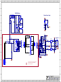
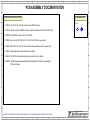
Assembly Documentation
Section:
Product(s):
Assembly.SchDoc
M1538 4 5Sheet OfPCB#: Rev#:
Modified:
V03
File:28/11/2014
YX15PC
EML Rev#: 03
Tmp Rev: V23
SPACERS
PCB HARDWARE
1. PCBSA: Q3, Q4, Q5, Q6, Q7 & Q8 are bent over the PCB face down.
2. PCBSA: Add nylon spacers YS#8656 to the two outter most leads of Q3, Q4, Q5, Q6, Q7 & Q8.
3. PCBSA: Add YS#4007 spacers to LD1, LD2 and LD3.
4. PCBSA: Lay down and RTV C38, C40, C35, C36, C39 & C41 before wave solder.
5. PCBSA: Zip-tie C35, C36, C39, C41 down with the locking mechanism on the capacitor side.
6. PCBSA: Clip all leads down to pad size before wave solder.
7. PCBSA: Add RTV to all small electrolytic caps to secure them from vibration.
8. WIRING: Add thermal grease between R36A and the adjacent stand-off when mounting the
PCB to the chassis.
SPECIAL PRODUCTION NOTES
.9 LED Spacer
4007
1/4" Nylon Spacer
8656
x 3 x 12
THIS SHEET CONTAINS SPECIAL PRODUCTION NOTES AND A LIST OF PCB HARDWARE PARTS REQUIRED FOR THE BUILD.
PCB ASSEMBLY DOCUMENTATION

1
1
2
2
3
3
4
4
5
5
6
6
7
7
8
8
9
9
10
10
11
11
12
12
13
13
14
14
15
15
16
16
17
17
K K
J J
I I
H H
G G
F F
E E
D D
C C
B B
A A
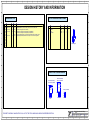
Design Information And History
Section:
Product(s):
History.SchDoc
M1538 5 5Sheet OfPCB#: Rev#:
Modified:
V03
File:28/11/2014
YX15PC
EML Rev#: 03
Tmp Rev: V23
CHANGE HISTORY POTENTIOMETERS AND KNOBS
LEADS AND PINS REFERENCE
DESIGN HISTORY AND INFORMATION
THIS SHEET CONTAINS A CHANGE HISTORY LOG, A LIST OF THE POTS & KNOBS AND A LEADS & PINS REFERENCE SECTION.
"STYLE_P32"
P1
P2
P3
P4
86534434
4434
4435
4432
.
.
.
.
.
.
.
.
8653
8653
8653
.
.
.
.
.
.
.
.
LINE IN LEVEL
REF POT#FUNCTION KNOB#
MIC LEVEL
.
.
.
.
.
.
.
.
TREBLE
BASS
.. .
.
.
.
.
.
.
.
.
.
STYLE
P32
P32
P32
P32
.
.
.
.
.
.
.
.
.
IRFP140N (YS#6931)
TO-247AC
D S
IRFP9140N (YS#6932)
G
2SD2560 (YS#6805)
TO3P
2SB1647 (YS#6812)
B C E
TO92
E B C
2N6517 (YS#6854)
.V01 FIRST PRODUCTION RELEASE. - ML
Substituted YS#5255 (1u 63V) for 5254 (1u 63V). See PC for details. - ML
GND scheme changed (see PC for details)
R106 and R127 changed from 1K0 (#7621) to 470R (#7856).
R109 and R125 changed from 33K (#7863) to 27K4 (#7636).
Tack on two diodes (#6438) on U1 and U2 as per PC#8734 V02 and earlier version.
D25,D26 #6438 (1N4007) added across the output of 7815 and 7915 regulators.
.
.
.
.
.
V01
V02
V02
V03
.
.
.
.
.
.
26-NOV-2013
13
10
7
4
1
9
11
12
8
#
2
3
5
6
VER#DATE DESCRIPTION OF CHANGE
NOV-13-2014
NOV-27-2014
.
.
.
.
18-DEC-2013
MAY-15-2014
.
PC#
8618
8632
8733
8734
8734
.
.
.
.
.
.
-
 1
1
-
 2
2
-
 3
3
-
 4
4
-
 5
5
-
 6
6
-
 7
7
-
 8
8
-
 9
9
-
 10
10
-
 11
11
-
 12
12
-
 13
13
-
 14
14
-
 15
15


YORKVILLE YX15PC Manuel utilisateur
- Catégorie
- Équipement musical supplémentaire
- Taper
- Manuel utilisateur
Documents connexes
-
YORKVILLE NX300P Manuel utilisateur
-
 YORKVILLE NX25P-2 Manuel utilisateur
-
YORKVILLE NX10C Manuel utilisateur
-
 YORKVILLE NX25P-2 Manuel utilisateur
-
 YORKVILLE NX750P Manuel utilisateur
-
 YORKVILLE YX15PC Le manuel du propriétaire
-
-
 YORKVILLE YX18SPC Manuel utilisateur
-
 YORKVILLE NX55P-2 Manuel utilisateur
-
Yorkville Sound MP6D2 Manuel utilisateur


