Frigidaire FGDS3065PF Guide d'installation
- Catégorie
- Micro-ondes
- Taper
- Guide d'installation

INSTALLATION INSTRUCTIONS
30" DUAL FUEL SLIDE-IN RANGE
Printed in United States
Important Notes to the Installer
1. Read all instructions contained in these installation
instructions before installing range.
2. Remove all packing material from the oven and the
drawer compartments before connecting the gas and
electrical supply to the range.
3. Observe all governing codes and ordinances.
4. Be sure to leave these instructions with the consumer.
5. Note: For operation at 2000 ft. elevations above see
level, appliance rating shall be reduced by 4 percent for
each additional 1000 ft.
Important Note to the Consumer
Keep these instructions with your owner's guide for the
local electrical inspector's use and future reference.
INSTALLATION AND SERVICE MUST BE PERFORMED BY A QUALIFIED INSTALLER.
IMPORTANT: SAVE FOR LOCAL ELECTRICAL INSPECTOR'S USE.
READ AND SAVE THESE INSTRUCTIONS FOR FUTURE REFERENCE.
United States
Canada
Refer to your serial
plate for applicable
agency certication.
Table of Contents
Important Safety Instructions .......................................2-3
Cabinet & Product Dimensions....................................3-4
To Avoid Breakage .......................................................... 5
Factory Connected Power Supply Cord (Canada only).. 6
Power Supply Cord Kit (U.S.A.)...................................... 6
Access to Terminal Block & Grounding Strap (U.S.A.) ... 6
Electrical Connection to the Range (U.S.A.) ............... 7-8
Cabinet Construction ...................................................... 9
Gas Supply - Installation............................................9-10
LP/Propane Gas Conversion ........................................ 10
Moving the Appliance for servicing and Cleaning ..........11
Range Installation .................................................... 11-12
Leveling the Range....................................................... 12
Check Operation......................................................12-14
When All Hookups are Complete.................................. 14
Model and Serial Number Location .............................. 14
Before You Call for Service........................................... 14
Anti-Tip Brackets Installation ................................... 15-16
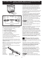
If the information in this manual is not followed exactly, a re
or explosion may result causing property damage, personal injury or death.
FOR YOUR SAFETY:
— Do not store or use gasoline or other ammable vapors and liquids in
the vicinity of this or any other appliance.
— WHAT TO DO IF YOU SMELL GAS:
• Do not try to light any appliance.
• Do not touch any electrical switch; do not use any phone in your
building.
• Immediately call your gas supplier from a neighbor's phone. Follow the
gas supplier's instructions.
• If you cannot reach your gas supplier, call the re department.
— Installation and service must be performed by a qualied installer,
service agency or the gas supplier.
P/N 318201635 (1305) Rev. A
English – pages 1-16; Spanish - pages 17-32; Français – pages 33-48
Appliances Installed in the state of
Massachusetts:
This Appliance can only be installed in the state of
Massachusetts by a Massachusetts licensed plumber or
gastter.
This appliance must be installed with a three (3) foot / 36
in. long exible gas connector.
A"T" handle type manual gas valve must be installed in
the gas supply line to this appliance.
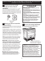
Cold temperature can damage the
electronic control. When using the appliance for the
rst time, or when the appliance has not been used
for an extended period, be certain the unit has been
in temperatures above 32°F (0°C) for at least 3 hours
before turning on the power to the appliance.

2
30" DUAL FUEL SLIDE-IN RANGE INSTALLATION INSTRUCTIONS
(Models with an Electric Oven and a Gas Cooktop)
Installation of this range must conform with local codes
or, in the absence of local codes, with the National Fuel
Gas Code ANSI Z223.1/NFPA54 or CAN/ACG-B149.1
and CAN/ACG-B149.2.
This range has been design certied by CSA
international. As with any appliance using gas and
generating heat, there are certain safety precautions
you should follow. You will nd them in the Use and
Care Guide, read it carefully.
• Air curtain or other overhead hoods, which operate
by blowing a downward air ow on to a range, shall
not be used in conjunction with gas ranges other
than when the hood and range have been designed,
tested and listen by an independent test laboratory
for use in combination with each other.
• Be sure your range is installed and grounded
properly by a qualied installer or service
technician.
• This range must be electrically grounded in
accordance with local codes or, in their absence,
with the National Electrical Code ANSI/NFPA No.
70—latest edition in United States or with CSA
Standard C22.1, Canadian Electrical Code, Part 1
in Canada.
• The installation of appliances designed for
manufactured (mobile) home installation must
conform with Manufactured Home Construction and
Safety Standard, title 24CFR, part 3280 [Formerly
the Federal Standard for Mobile Home Construction
and Safety, title 24, HUD (part 280)] or when
such standard is not applicable, the Standard for
Manufactured Home Installation 1982 (Manufactured
Home Sites, Communities and Setups), ANSI
Z225.1/NFPA 501A-latest edition, or with local codes
in United States and with CAN/CSA-Z240 MH in
Canada.
• Make sure the wall coverings around the range
can withstand the heat generated by the range.
• Before installing the range in an area covered
with linoleum or any other synthetic oor
covering, make sure the oor covering can
withstand heat at least 90°F above room
temperature without shrinking, warping or
discoloring. Do not install the range over carpeting
unless you place an insulating pad or sheet of ¼"
(0,6 cm) thick plywood between the range and
carpeting.
• Do not obstruct the ow of combustion air at
the oven vent nor around the base or beneath
the lower front panel of the range. Avoid touching
the vent openings or nearby surfaces as they
may become hot while the oven is in operation.
This range requires fresh air for proper burner
combustion.
Never leave children alone or
unattended in the area where an appliance is in
use. As children grow, teach them the proper, safe
use of all appliances. Never leave the oven door open
when the range is unattended.
Stepping, leaning or sitting on the
doors or drawers of this range can result in serious
injuries and can also cause damage to the range.
• Do not store items of interest to children in
the cabinets above the range. Children could be
seriously burned climbing on the range to reach
items.
• To eliminate the need to reach over the surface
burners, cabinet storage space above the
burners should be avoided.
• Adjust surface burner ame size so it does not
extend beyond the edge of the cooking utensil.
Excessive ame is hazardous.
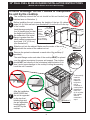
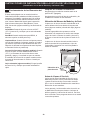
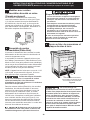
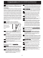
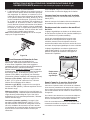
A child or adult can tip the range and •
be killed.
Verify the anti-tip device has been •
installed to oor or wall as per
installation instructions.
Tip Over Hazard
Ensure the anti-tip device is re-engaged to oor or •
wall when the range is moved.
Do not operate the range without the anti-tip device •
in place and engaged.
Failure to follow these instructions can result in •
death or serious burns to children and adults.
To check if the anti-tip bracket is installed
properly, use both arms and grasp
the rear edge of range back. Carefully
attempt to tilt range forward. When
properly installed, the range should not
tilt forward.
Refer to the anti-tip bracket installation instructions
supplied with your range for proper installation.
This manual contains important safety symbols and instructions. Please pay attention to these symbols and
follow all instructions given.
This symbol will help alert you to situations that may cause serious bodily harm, death or
property damage.
This symbol will help alert you to situations that may cause bodily injury or property
damage.
IMPORTANT SAFETY INSTRUCTIONS

30" DUAL FUEL SLIDE-IN RANGE INSTALLATION INSTRUCTIONS
(Models with an Electric Oven and a Gas Cooktop)
3
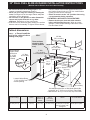
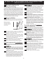
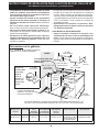
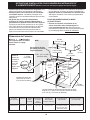
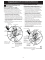
1/2” min.
1/4” min.
WALL
5" Min.
(12,7 cm Min.)
From Wall Both Sides
30" Min.
(76,2 cm Min.)
30" Min.
(76,2 cm) Min.
(see Note 3)
18" Min.
(45,7 cm) Min.
Approx. 1 7/8"
(4,8 cm)
Grounded Junction Box or Wall Outlet Should Be
Located 8" to 17" (20,3 cm to 43,2 cm) From Right
Cabinet and 2" to 4" (5,1 cm to 10,2 cm) From Floor.
Locate Cabinet Doors
1" (2,5 cm) Min. from
Cutout Opening.
E
G
F
31 ½"
(80 cm)
Exact
13"
(33 cm)
24" Min.
(61 cm Min.)
Shave Raised
Edge to Clear
Space for a
31 ½" (80
cm) Wide
Cooktop.
1 ½" Max.
(3,8 cm Max.)
These surfaces
should be at &
leveled (hatched
area).
Do not install the
unit in the cabinet before
reading next page.
A. HEIGHT
(Under Cooktop)
B. WIDTH C. COOKTOP
WIDTH
D. TOTAL
DEPTH TO
FRONT OF
RANGE
E. CUTOUT
WIDTH
(Countertop
and cabinet)
F. CUTOUT
DEPTH
G. HEIGHT
OF COUNTERTOP
35 7/8" (91,1 cm)
36 5/8" (93 cm)
30"
(76,2 cm)
31 1/2"
(80 cm)
28 5/16"
(71,9 cm)
30±1/16"
(76,2±0,15 cm)
21 3/4" (55,2 cm) Min.
22 1/8" (56,2 cm) Max
24" (61 cm) Min. with
backguard
35 7/8" (91,1 cm) Min.
36 5/8" (93 cm) Max.
• Do not use the oven as a storage space. This
creates a potentially hazardous situation.
• Never use your range for warming or heating the
room. Prolonged use of the range without adequate
ventilation can be dangerous.
• Do not store or use gasoline or other ammable
vapors and liquids near this or any other
appliance. Explosions or res could result.
• In the event of an electrical power outage, the surface
burners can be lit manually. To light a surface burner,
hold a lit match to the burner head and slowly turn
the Surface Control knob to LITE. Use caution when
lighting surface burners manually.
• Reset all controls to the "off" position after using
a programmable timing operation.
FOR MODELS WITH SELF-CLEAN FEATURE:
• Remove broiler pan, food and other utensils
before self-cleaning the oven. Wipe up excess
spillage. Follow the precleaning instructions in the
Use and Care Guide.
Cabinet dimensions

4
30" DUAL FUEL SLIDE-IN RANGE INSTALLATION INSTRUCTIONS
(Models with an Electric Oven and a Gas Cooktop)
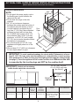
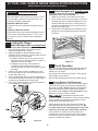
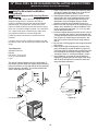
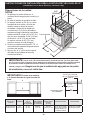
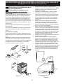
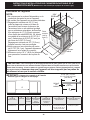
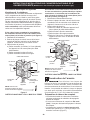
NOTE:
1. Do not pinch the power supply cord or
the exible gas conduit between the
range and the wall.
2. Do not seal the range to the side
cabinets.
3. 24" (61 cm) minimum clearance
between the cooktop and the bottom of
the cabinet when the bottom of wood
or metal cabinet is protected by not
less than ¼" (0,64 cm) ame retardant
millboard covered with not less than
No. 28 MSG sheet metal, 0,015" (0,4
mm) stainless steel, 0.024" (0,6 mm)
aluminum, or 0,020" (0,5 mm) copper.
30" (76,2 cm) minimum clearance when
the cabinet is unprotected.
4. For cutouts below 22 7/8" (58,1 cm),
appliance will slightly show out of the
cabinet.
5. Allow at least 19 ¼" (48,9 cm) clearance
for door depth when it is open.
21¾”
(55.25 cm)
D
C
A
B
Door
Open
Side Panel
1 1/8"
(2,86 cm)
FRONT OF
CABINET
F
Ref.
22 7/8" (58,1 cm) min.
23 1/4" (59,05 cm) max.
(see Note 4)
* IMPORTANT: To avoid cooktop breakage for cutout width (E dimension) of more
than 30 1/16" (76,4 cm), make sure the appliance is centered in the counter opening
while pushing into it. Raise leveling legs at a higher position than the cabinet height
(see page 3), insert the appliance in the counter and then level.
Make sure the unit
is supported by the leveling legs and NOT by the cooktop itself.
IMPORTANT: Cabinet and countertop
width should match the cutout width.
E
E
A. HEIGHT
(Under Cooktop)
B. WIDTH C.
COOKTOP
WIDTH
D. TOTAL
DEPTH TO
FRONT OF
RANGE
E. CUTOUT
WIDTH*
(Countertop
and cabinet)
F. CUTOUT
DEPTH
G. HEIGHT
OF COUNTERTOP
35 7/8" (91,1 cm)
36 5/8" (93 cm)
30"
(76,2 cm)
31 1/2"
(80 cm)
28 5/16"
(71,9 cm)
30±1/16"
(76,2±0,15 cm)
21 3/4" (55,2 cm) Min.
22 1/8" (56,2 cm) Max
24" (61 cm) Min. with
backguard
35 7/8" (91,1 cm) Min.
36 5/8" (93 cm) Max.
Product dimensions

30" DUAL FUEL SLIDE-IN RANGE INSTALLATION INSTRUCTIONS
(Models with an Electric Oven and a Gas Cooktop)
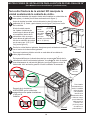
5
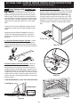
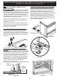
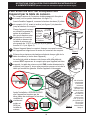
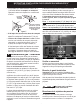
After the installation,
MAKE SURE that
the unit is supported
by the two front
leveling legs and
the two adjustable
leveling wheels
and NOT by the
cooktop.
Before installing the unit, measure the heights of the two (2) cabinet
sides (H1-4), front and back (see illustration 1) from the oor to the top
of the counter.
H1
H2
H3
H4
To avoid breakage: Do NOT handle or manipulate
the unit by the cooktop.
The counter-top around the cut-out should be at and leveled (see
hatched area on illustration 1).
1
2
3
Illustration 1
Shave
Raised
Edge
to Clear
Space for a
31½" (80 cm)
Wide Cooktop.
1 ½" Max.
(3.8 cm Max.)
Illustration 2
To successfully
install the
range, the
initial level
height from
oor to
underside of
cooktop frame
should be at
least 1/16"
(0,16 cm) taller
than cabinet
sides as
measured in
step 2.
Level the range using the
four (4) leveling legs, so that
the height from the oor to
the underside of the metal
ange is greater than the
tallest cabinet measurement
by at least 1/16" (0,16 cm)
(see illustration 2).
Metal
Flange
8
Remove the protective channels on each side of the cooktop (if
provided).
Slide the unit into the cabinet. Make sure the center of the unit is
aligned with the center of the cabinet cut-out.
5
6
7
4
The metal ange under each side of the cooktop MUST be placed
over the cabinet countertop for proper unit support. The cooktop
should NOT rest directly on the countertop (see illustration 2) or
else it could cause damage to the cooktop voiding the warranty.
Level the unit if needed.

6
30" DUAL FUEL SLIDE-IN RANGE INSTALLATION INSTRUCTIONS
(Models with an Electric Oven and a Gas Cooktop)
Canada Style
Figure 1
2
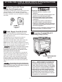
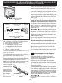
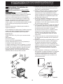
Power Supply Cord Kit (U.S.A.)
The user is responsible for connecting the power
supply cord to the connection block located behind the
back panel access cover.
This appliance may be connected by means of
permanent "hard wiring"; exible armored or
nonmetallic shielded copper cable (when local code
allow it) or by means of a power supply cord kit.
NOTE: Electric Slide-in Range is shipped from factory
with 1 1/8" (2.9 cm) dia. hole as shown on gure 4. If a
larger hole is required, punch out the knockout.
Risk of re or electrical shock exists
if an incorrect size range cord kit is used, the
Installation Instructions are not followed, or the
strain relief bracket is discarded.
For mobile homes, new installations or recreational
vehicles, use only a power supply kit designed for a
range at 125V/250V 30A recommended. Cord must
have either 3 (when local code permits grounding
through neutral) or 4 conductors. Terminal on end
of wires must be either closed loop or open spade
lug with upturned ends. Cord must have strain-relief
clamp.
Do not loosen the nuts which secure
the factory-installed range wiring to terminal block
while connecting range. Electrical failure or loss of
electrical connection may occur.
3
Access to Terminal Block &
Grounding Strap (U.S.A.)
Electrical Shock Hazard
• Electrical ground is required on this
appliance.
• Do not connect to the electrical supply until
appliance is permanently grounded.
• Disconnect power to the circuit breaker
or fuse box before making the electrical
connection.
• This appliance must be connected to a
grounded, metallic, permanent wiring
system, or a grounding connector should be
connected to the grounding terminal or wire
lead on the appliance.
Failure to do any of the above could result in a
re, personal injury or electrical shock.
1
Factory Connected Power
Supply Cord (Canada only)
This range is equipped with a factory-connected power
cord (see Figure 1). Cord must be connected to a
grounded 120/240 volt or 120/208 volt range outlet. If
no outlet is available, have one installed by a qualied
electrician.
This appliance is manufactured
with the frame grounded by connection of a
grounding strap between the neutral power
supply terminal and the frame. If used in USA,
in a new branch circuit installation (1996 NEC),
mobile home or recreational vehicle, where
local code do not permit grounding through
neutral (white) wire or in Canada; remove the
grounding strap from the frame and cut the
other end, near the neutral terminal. Connect
the appliance in usual manner.
Remove the wire cover here
for access to terminal block
Figure 2

30" DUAL FUEL SLIDE-IN RANGE INSTALLATION INSTRUCTIONS
(Models with an Electric Oven and a Gas Cooktop)
7
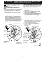
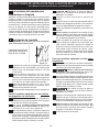
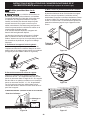
Four Conductor Wire Connection to Range
Where local codes does NOT permit connection of the
frame grounding conductor to the neutral wire of the
copper power supply cord (see Figure 4):
1. Remove the screw which is xing the rear wire
cover, then remove the rear wire cover (access
cover) to expose range terminal connection block
(see Figure 2).
2. Remove the grounding strap from the terminal
block and from the appliance frame.
3. Using the nuts supplied with the literature package,
connect the ground wire (green) of the copper
power supply cord to the frame of the appliance with
the ground screw, using the hole in the frame where
the ground strap was removed (see Figure 4).
4. Connect the neutral of the copper power supply
cord to the center silver-colored terminal of the
terminal block, and connect the other wires to the
outer terminals. Match wires and terminals by color
(red wires connected to the right terminal, black
wires connected to the left terminal).
5. Put back the rear wire cover using the screw
removed on step 1.
Terminal Block
Silver Colored Terminal
Red
Wire
Neutral
(White Wire)
Ground (Bare
Copper Wire)
To 240 V Receptacle
A User Supplied
Strain-relief Must
Be Installed at
This Location
Black Wire
1 1/8" (2,9cm)
Dia. Direct
Connection
Hole. Punch
Out Knockout
for 1 3/8" (3,5
cm) Dia. Cord
Kit Hole.
NOTE: Be sure to remove the
supplied grounding strap.
Figure 4
4
Electrical Connection to the
Range (U.S.A.)
Three Conductor Wire Connection to
Range
If local codes permit connection of the frame grounding
conductor to the neutral wire of the copper power
supply cord (see Figure 3):
1. Remove the screw which is xing the rear wire
cover, then remove the rear wire cover (access
cover) to expose range terminal connection block
(see Figure 2).
2. Using the nuts supplied in the literature package,
connect the neutral of the copper power supply
cord to the center silver-colored terminal of the
terminal block, and connect the other wires to the
outer terminals. Match wires and terminals by color
(red wires connected to the right terminal, black
wires connected to the left terminal) (see gure 3).
3. Put back the rear wire cover using the screw
removed on step 1.
Figure 3
Silver Colored Terminal
1 1/8" (2,9 cm) Dia.
Direct Connection
Hole. Punch Out
Knockout for 1 3/8"
(3,5 cm) Dia. Cord
Kit Hole.
To 240 V
Receptacle
A User Supplied
Strain-relief Must
Be Installed at This
Location.
Black
Wire
Terminal
Block
Cord
Mounting
Plate
Neutral
(White Wire)
Grounding
Strap
Red Wire

8
30" DUAL FUEL SLIDE-IN RANGE INSTALLATION INSTRUCTIONS
(Models with an Electric Oven and a Gas Cooktop)
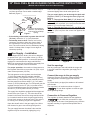
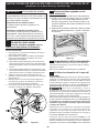
Direct Electrical Connection to the Circuit
Breaker, Fuse Box or Junction Box
If the appliance is connected directly to the circuit
breaker, fuse box or junction box, use exible, armored
or nonmetallic sheathed copper cable (with grounding
wire). Supply a U.L. listed strain-relief at each end of
the cable. At the appliance end, the cable goes through
the Direct Connection Hole (see Figure 5) on the
Cord Mounting Plate. Wire sizes (copper wire only)
and connections must conform to the rating of the
appliance. A 50A time-delay fuse or circuit breaker is
recommended (minimum 40A).
Where local codes permit connecting the
appliance-grounding conductor to the neutral
(white) wire (see Figure 5):
1. Be sure that no power is supplied on the cable from
residence.
2. Remove the grounding strap from the terminal block
and from the appliance frame.
3. In the circuit breaker, fuse box or junction box:
a) Connect the green (or bare copper) wire, the
white appliance cable wire, and the neutral (white)
wire together.
b) Connect the 2 black wires together.
c) Connect the 2 red wires together.
Figure 5
3-Wire (Grounded Neutral) Electrical System
(Example: Junction Box)
Cable from Residence
Junction
Box
White Wire
U.L.-listed Conduit
Connector (or CSA
listed)
Cable from
Appliance
Green
(or Bare Copper)
Wire
Red
Wires
Neutral
(white) Wire
Black
Wires
NOTE: Be sure to remove the
supplied grounding strap.
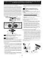
Where local codes DO NOT permit connecting
the appliance-grounding conductor to the neutral
(white) wire, or if connecting to 4-wire electrical
system (see Figure 6):
1. Be sure that no power is supplied on the cable
from residence.
2. Remove the grounding strap from the terminal
block and from the appliance frame.
3. In the circuit breaker, fuse box or junction box:
a) Connect the white appliance cable wire to the
neutral (white) wire.
b) Connect the 2 black wires together.
c) Connect the 2 red wires together.
d) Connect the green (or bare copper) grounding
wire to the grounding wire of the circuit breaker,
fuse box or junction box.
NOTE: Be sure to remove the
supplied grounding strap.
U.L.-listed Conduit
Connector (or CSA
listed)
Figure 6 – 4-Wire Electrical System
(Example: Junction Box)
Cable from Residence
Black
Wires
Junction
Box
White Wire
Cable from
Appliance
Green (or Bare
Copper) Wire
Red
Wires
White Wire
Green (or Bare
Copper) Wire
5
Cabinet Construction
To eliminate the risk of burns or re
by reaching over heated surface units, do not have
cabinet storage space above the range. If there is
cabinet storage space above range, reduce risk by
installing a range hood that projects horizontally a
minimum of 5" (12,7 cm) beyond the bottom of the
cabinet.
Countertop Preparation
• The cooktop sides of the range t over the cutout
edge of your countertop.
• If you have a square nish (at) countertop, no
countertop preparation is required. Cooktop sides lay
directly on edge of countertop.
• Formed front-edged countertops must have
molded edge shaved at 3/4" (1,9 cm) from each
front corner of opening (Figure 7).

30" DUAL FUEL SLIDE-IN RANGE INSTALLATION INSTRUCTIONS
(Models with an Electric Oven and a Gas Cooktop)
9
Min.
Cutout
Width
Formed or tile countertop
trimmed ¾" (1,9 cm) back at
front corners of countertop
opening.
Figure 7
6
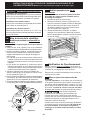
Gas Supply – Installation
When shipped from the factory, this unit is designed
to operate on 4" (10,16 cm) water column (1,0 kPa)
Natural gas manifold pressure. A convertible pressure
regulator is connected to the range manifold and
MUST be connected in series with the gas supply line.
To access the regulator, remove the drawer.
For proper operation, the maximum inlet pressure to
the regulator should be no more than 14" (35,6 cm) of
water column pressure (3,5 kPa).
The inlet pressure to the regulator must be at least
1" (0,25 kPa) greater than the regulator manifold
pressure setting. The regulator is set for 4" (10,2 cm)
water column (1,0 kPa) Natural gas manifold pressure;
the inlet pressure must be at least 5" (12,7 cm) water
column (1,25 kPa) Natural gas. For LP/Propane gas, the
regulator must be set for 10" (25,4 cm) water column
(2,5 kPa) manifold pressure; the inlet pressure must be
at least 11" (27,9 cm) water column (2,75 kPa).
The supply line should be equipped with an approved
shutoff valve (see Figure 11). This valve should be
located in the same room as the range and should be
in a location that allows ease of opening and closing.
Do not block access to the shutoff valve. The valve is
for turning on or shutting off gas to the appliance.
Open the shutoff valve in the gas supply line. Wait a
few minutes for gas to move through the gas line.
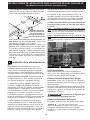
The gas supply between the shutoff valve and the
regulator may be connected by rigid piping or by
A.G.A./C.G.A.-approved exible metallic union-
connected piping where local codes permit use.
The gas supply piping can be through the back wall
(Figure 8, zone 1) or through the floor (Figure 8,
zone 2):
Zone 1 - Through the Back Wall (7" (17,8 cm) X 6"
(15,2 cm)) - The best place to have your gas line in is
between 1" (2,5 cm) and 8" (20,3 cm) from the oor and
within 3" (7,6 cm) from the center line.
Zone 2 - Through the Floor (~2" (5,1 cm) X 24" (61
cm)) - The gas line can also come through the floor
within 12" (30,5 cm) from the center line against the
back wall.
Seal the openings
Seal any openings in the wall behind the range and
in the oor under the range after gas supply line is
installed.
Connect the range to the gas supply
Important: Remove all packing material and literature
from range before connecting gas and electrical
supply.
To prevent leaks, put pipe joint sealant on all external
pipe threads.
Your regulator is in location as shown in gure 9.
Do not allow regulator to rotate on pipe
when tightening ttings.
Connection to Pressure Regulator
The regulator is already installed on the appliance.
Do not make the connection too tight.
The regulator is die cast. Overtightening may crack the
regulator resulting in a gas leak and possible re or
explosion.
Figure 8
• Tile countertops may need trim cut back 3/4"(1,9
cm) from each front corner and/or rounded edge
attened (Figure 7).
• If the existing cutout width is greater than 30 1/16"
(76,4 cm), reduce the ¾" (1,9 cm) dimension.
• Countertop must be level. Place a level on the
countertop, rst side to side, then front to back. If
the countertop is not level, the range will not be
level. The oven must be level for satisfactory baking
results. Cooktop sides of range t over edges of
countertop opening.

10
30" DUAL FUEL SLIDE-IN RANGE INSTALLATION INSTRUCTIONS
(Models with an Electric Oven and a Gas Cooktop)
Assemble the exible connector from the gas supply
pipe to the pressure regulator in the following order:
1. manual shutoff valve (not supplied)
2. 1/2" nipple (not supplied)
3. 1/2" are union adapter (not supplied)
4. exible connector (not supplied)
5. 1/2" are union adapter (not supplied)
6. 1/2" nipple (not supplied)
7. pressure regulator (supplied)
The gas supply line to the shutoff valve should be
1/2" (1,27 cm) or 3/4" (1,9 cm) solid pipe.
The user must know the location of the main shutoff
valve and have easy access to it.
When using exible gas conduit on the range, allow
sufcient slack to pull the range outside the cutout for
cleaning or servicing.
NOTE: Do not allow the exible conduit to get pinched
between the wall and the range. To visually check,
remove the range drawer.
Use pipe-joint compound made for use with Natural
and LP/
Propane gas
to seal all gas
connections.
If exible
connectors
are used,
be certain
connectors
are not kinked.
All connections must be wrench-tightened
Figure 10
Flare
Union
Flare
Union
GAS FLOW
Manual
Shutoff
Valve
Pressure
Regulator
On
Off
Flexible
Connector
Access
Cap
Nipple Nipple
Shutoff Valve -
Open position
to appliance
to gas supply line
Figure 11
The supply line must be equipped with an approved
manual shutoff valve. This valve should be located
in the same room as the range and should be in a
location that allows ease of opening and closing. Do
not block access to the shutoff valve. The valve is for
turning on or shutting off gas to the appliance.
Once regulator is in place, open the shutoff valve in the
gas supply line. Wait a few minutes for gas to move
through the gas line.
Leak testing of the appliance shall be conducted
according to the manufacturer's instructions.
Check for leaks. After connecting the range to the gas
supply, check the system for leaks with a manometer.
If a manometer is not available, turn on the gas
supply and use a liquid leak detector at all joints and
connections to check for leaks.
Do not use a ame to check for leaks
from gas connections. Checking for leaks with a ame
may result in a re or explosion.
All openings in the wall or oor where the range is to
be installed must be sealed.
Tighten all connections if necessary to prevent gas
leakage in the cooktop or supply line.
Disconnect this range and its individual shutoff
valve from the gas supply piping system during any
pressure testing of the system at test pressures greater
than 1/2 psig (3,5 kPa or 14" (35,56 cm) water column).
Isolate the range from the gas supply piping
system by closing its individual manual shutoff valve
during any pressure testing of the gas supply piping
system at test pressures equal to or less than 1/2 psig
(3,5 kPa or 14" (35,56 cm) water column).
7
LP/Propane Gas Conversion
This appliance can be used with Natural gas or LP/
Propane gas. It is shipped from the factory for use with
natural gas.
If you wish to convert your range for use with LP/
Propane gas, use the supplied xed orices located
in a bag containing the literature marked "FOR
LP/PROPANE GAS CONVERSION". Follow the
instructions packaged with the orices.
The conversion must be performed by a qualied
service technician in accordance with the
manufacturer's instructions and all local codes and
requirements. Failure to follow these instructions
could result in serious injury or property damage.
The qualied agency performing this work assumes
responsibility for the conversion.
Failure to make the appropriate
conversion can result in personal injury and property
damage.
Pressure
regulator location
Figure 9

30" DUAL FUEL SLIDE-IN RANGE INSTALLATION INSTRUCTIONS
(Models with an Electric Oven and a Gas Cooktop)
11
9.8
To reduce the risk of damaging
your appliance, do not handle or manipulate it by the
cooktop or control console. Manipulate with care.
9.9
Position range in front of the cabinet opening.
9.10
Make sure that the cooktop which overhangs the
countertop clears the countertop. If necessary,
raise the unit by lowering the leveling legs.
9.11
Slide the range into the cutout opening and center
it before leveling it.
9.12
Level the range (see section 10). The oor where
the range is to be installed must be level. Follow
the instructions under "Leveling the Range-
Models Equipped with Leveling Device".
9.13
Adjust leveling legs so that the underside of the
cooktop is sitting on the countertop. Carefully
screw in (refer to Leveling the range: Models
equipped with Leveling Device") the back leveling
leg until the cooktop overhang touches slightly the
countertop. Then carefully screw in the front two
leveling legs until the cooktop overhang touches
slightly the countertop.
For models equipped with Leveling Leg
only (no leveling device):
9.5
Make sure the four leveling legs (front and rear)
are setup higher than the height of the cabinet.
9.6
Install the anti-tip bracket
at this point before placing the range at its
nal position. Follow the installation instructions
on page 17 or on the anti-tip bracket template
supplied with the range.
9.7
To provide an optimum installation, the top surface
of the countertop must be level and at (lie on the
same plane) around the 3 sides that are adjacent
to range cooktop. Proper adjustments to make
the top at should be made or gaps between the
countertop and the range cooktop may occur.
9.8
To reduce the risk of damaging
your appliance, do not handle or manipulate it by
the cooktop. Manipulate with care.
9.9
Position range in front of the cabinet opening.
9.10
Make sure that the cooktop which overhangs the
countertop clears the countertop. If necessary,
raise the unit by lowering the leveling legs.
9.11
Level the range (see section 10). The oor where
the range is to be installed must be level. Follow
the instructions under "Leveling the Range-Models
Equipped with Leveling Legs".
9.12
Slide the range into the cutout opening.
8
Moving the Appliance for
Servicing and Cleaning
Turn off the range line fuse or circuit breakers at the main
power source, and turn off the manual gas shut-off valve.
Make sure the range is cold. Remove the service drawer
(warmer drawer on some models) and open the oven door.
Lift the range at the front and slide it out of the cut-out
opening without creating undue strain on the exible gas
conduit. Make sure not to pinch the exible gas conduit at
the back of the range when replacing the unit into the cut-
out opening. Replace the drawer, close the door and switch
on the electrical power and gas to the range.
9
Range Installation
Important Note: Door removal is not a requirement for
installation of the range, but is an added convenience.
Figure 12
Refer to the Use
and Care Guide for
oven door removal
instructions.
9.1
The range cooktop overlaps the countertop at
the sides and the range rests on the floor. The
cooktop is 31 1/2" (80 cm) wide.
9.2
Install base cabinets 30" (76,2 cm) apart. Make
sure they are plumb and level before attaching
cooktop. Shave raised countertop edge to clear
31 1/2" (80 cm) wide range top rim.
9.3
Install cabinet doors 31" (78,7 cm) min. apart so it
will not interfere with range door opening.
9.4
Cutout countertop exactly as shown on page 3.
For models equipped with Leveling Device:
9.5
Make sure the front leveling legs and the rear
leveling device are setup higher than the height of
the cabinet.
9.6
Install the anti-tip bracket
at this point before placing the range at its
nal position. Follow the installation instructions
on page 16 or on the anti-tip bracket template
supplied with the range.
9.7
To provide an optimum installation, the top surface
of the countertop must be level and at (lie on the
same plane) around the 3 sides that are adjacent
to range cooktop. Proper adjustments to make
the top at should be made or gaps between the
countertop and the range cooktop may occur.

12
30" DUAL FUEL SLIDE-IN RANGE INSTALLATION INSTRUCTIONS
(Models with an Electric Oven and a Gas Cooktop)
11
Check Operation
Refer to the Use and Care Guide packaged with the
range for operating instructions and for care and
cleaning of your range.
Do not touch the elements or burners. They may be
hot enough to cause burns.
Remove all packaging from the oven before testing.
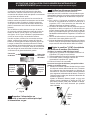
11.1
Check Burner Cap Placement
It is very important to be sure that all surface burner
caps and burner grates are properly installed and in
the correct locations before operating the appliance.
Please note that the burner heads are secured to
the cooktop. The cooktop is not removable. Do not
attempt to remove or lift the cooktop.
To prevent are-ups and avoid
creation of harmful by-products, do not use the cooktop
without all burner caps properly installed to insure
proper ignition and gas ame size.
Always keep the burner caps and burner heads in
place whenever the surface burners are in use. DO
not allow spills, food, cleaning agents or any other
material to enter the gas orice holder openings.
Check and be sure the size of each burner cap
matches the size of the burner head. Check and be
sure that all round style burner caps are correctly in
place on round burner heads.
Figure 13
10.
Leveling the Range
10.1
Models Equipped with Leveling Device
Level the range after installation in the cutout opening.
1. Open the range drawer. The leveling screws
control the height of the rear leg.
2. Adjust the appliance legs as follows until the
underside of the cooktop (or cooktop glass) surface
is sitting level on the countertop.
a. To adjust the front legs, use a wrench on the
leg base and turn counterclockwise to lower or
clockwise to raise the range.
b. To adjust the rear legs, use a ratchet or
a nutdriver and turn the leveling screws
counterclockwise to lower or clockwise to raise
the range.
3. Check if the range is level by installing an oven
rack in the center of the oven and placing a level
on the rack (Figure 14).
4. Take 2 readings with the level placed diagonally in
one direction and then the other. Level the range, if
necessary, by adjusting the leveling legs.
5. If the range cannot be level, contact a carpenter to
correct sagging or sloping oor.
10.2
Models Equipped with Leveling Legs
Level the range and set cooktop height before
installation in the cut-out opening.
1. Install an oven rack in the center of the oven.
2. Place a level on the rack (see Figure 14). Take 2
readings with the level placed diagonally in one
direction and then the other. Level the range, if
necessary, by adjusting the 4 leg levelers with a
wrench (see Figure 26).
3. Taking care to not damage the countertop, slide
range into cutout opening and double check for
levelness.
Figure 14
IMPORTANT
If Accessories Needed:
Installation With Backguard
The cutout depth of (21 3/4" (55,2 cm) Min., 22 1/8"
(56,2 cm) Max.) needs to be increased to 24" (61
cm) when installing a backguard.
Installation With End Panel
A End Panel kit can be ordered through a Service
Center.
Installation With Side Panels
A Side Panels kit can be ordered through a Service
Center. Note: Install cabinet doors 31" (78.7 cm)
min. apart so as not to interfere with range door
opening.

30" DUAL FUEL SLIDE-IN RANGE INSTALLATION INSTRUCTIONS
(Models with an Electric Oven and a Gas Cooktop)
13
A
B
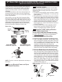
NOTE: There are no burner adjustments necessary on
this range.
11.2
Turn on Electrical Power and Open
Main Shutoff Gas Valve
Burner Cap
Burner
Head
Figure 15
Figure 18
Correct Burner Cap
Placement - Figure 16
Incorrect Burner Cap
Placement - Figure 17
Burner
Cap Lip
Check and be sure that all oval style burner caps are
correctly in place on oval burner heads (if equipped).
Check and be sure that all dual or twin style burner
caps are correctly in place on dual or twin heads (if
equipped).
On round style burners, the burner cap lip (Figure 15)
should t snug into the center of burner head and be
level. Refer to gures 16 & 17 for correct and incorrect
burner cap placement.
Once in place, you may check the t by gently sliding
the burner cap from side to side (Figure 18) to be sure
it is centered and rmly seated. When the burner cap lip
makes contact inside the center of the burner head you
will be able to hear the burner cap click. Please note
that the burner cap should NOT move off the center of
the burner head when sliding from side to side.
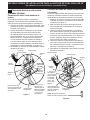
11.3
Check the Igniters
Operation of electric igniters should be checked after
range and supply line connectors have been carefully
checked for leaks and range has been connected to
electric power.
a. To check for proper lighting, push in and turn a surface
burner knob to the LITE position. You will hear the
igniter sparking.
b. The surface burner should ignite when gas is available
to the burner. Purge air from supply lines by leaving
knob in the LITE position until burner ignites. Each
burner should light within four (4) seconds in normal
operation after air has been purged from supply lines.
c. Visually check that burner has a ame, Once the
burner ignites, the control knob should be turned out
of the LITE position.
d. Try each surface control knob separately until all
burner valves have been checked. Each burner
location is equipped with a separate electrode.
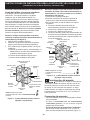
11.4
Adjust the "LOW" Setting of Surface
Burner Valves (linear ow)
Test to verify if LOW setting should be adjusted:
a. Push in and turn control to LITE until burner ignites.
b. Push in and quickly turn knob to lowest position.
c. If burner goes out, reset control to OFF.
d. Remove the surface burner control knob.
For all burner styles (except Dual and Bridge burner)
e. Insert a thin-bladed screwdriver into the hollow valve
stem and engage the slotted screw inside. Flame size
can be increased or decreased with the turn of screw.
Turn counterclockwise to increase ame size. Turn
clockwise to decrease ame size (Figure 19).
Adjust ame until you can quickly turn knob from LITE to
lowest position without extinguishing the ame. Flame
should be as small as possible without extinguishing.
For Dual and Bridge burner style adjustment only:
e. The inner portion (Simmer) of the dual burner ame
size or the rear portion of the bridge burner ame size
can be increase or decrease with the turn of screw A.
Use screw B to adjust ame size of the outer portion
of the Dual Burner or the center portion of the Bridge
Burner (Figure 20). Turn the screw counterclockwise
to increase ame size. Turn clockwise to decrease
ame size. Adjust ame size until you can quickly
turn the knob from LITE to lowest position without
extinguishing the ame. Flame should be as small as
possible without going out.
Note: Air mixture adjustments are not required on
surface burners.
Hollow
Valve
Stem
Figure 19
Figure 20

14
30" DUAL FUEL SLIDE-IN RANGE INSTALLATION INSTRUCTIONS
(Models with an Electric Oven and a Gas Cooktop)
Serial Plate
Location
11.6
Operation of Oven Elements
The oven is equipped with an electronic oven control.
Each of the functions has been factory checked before
shipping. However, it is suggested that you verify the
operation of the electronic oven controls once more.
Refer to the Electronic Oven Control Guide for operation.
Follow the instructions for the Clock, Timer, Bake, Broil,
Convection (some models) and Clean functions.
Bake–Set the oven to 350°F (177°C) for baking, and
check to see if the oven is heating.
Broil–When the oven is set to BROIL, the upper
element in the oven should become red.
Clean–When the oven is set for a self-cleaning cycle,
the upper element should become red during the
preheat portion of the cycle. After reaching the self-
cleaning temperature, the lower element will become
red.
Convection (some models)–When the oven is set to
CONV. BAKE/ROAST at 350°F (177°C), the convection
element cycles on and off and the convection fan turns.
The convection fan will stop turning when the oven
door is opened during convection baking or roasting.
Warmer Drawer (some models)–Set the control knob
to HI and check to see the drawer is heating.
When All Hookups are Complete
Make sure all controls are left on the OFF position.
Make sure the ow of combustion and ventilation air to
the range is unobstructed.
Model and Serial Number Location
The serial plate is located on the oven front frame
behind the oven door (some models) or on the drawer
side frame (some models).
When ordering parts for or making inquiries about your
range, always be sure to include the model and serial
numbers and a lot number or letter from the serial plate
on your range.
Your serial plate also tells you the rating of the burners,
the type of fuel and the pressure the range was
adjusted for when it left the factory.
Before You Call for Service
Read the Avoid Service Checklist and operating
instructions in your Use and Care Guide. It may save
you time and expense. The list includes common
occurrences that are not the result of defective
workmanship or materials in this appliance.
Refer to the warranty and service information in your
Use and Care Guide for phone number and address.
Please call or write if you have inquiries about your
range product and/or need to order parts.

30" DUAL FUEL SLIDE-IN RANGE INSTALLATION INSTRUCTIONS
(Models with an Electric Oven and a Gas Cooktop)
15
(
C
L = Center line)
Range
Anti-Tip Bracket
Floor Mount
Screws
Floor
Rear of Range
Wall
1. Draw a center line (CL) on the oor where the range
should be installed. Also draw a line on the oor at
the range back position if there is no wall.
2. Unfold paper template and place it at on the oor
with the right rear corner positioned exactly on the
intersection of the center and back lines you just
drew before. (Use the diagram below to locate
brackets if template is not available (Figure 21)).
3. Mark on the oor the location of the 4 mounting holes
shown on the template. For easier installation, 3/16"
(0,48 cm) diameter pilot holes 1/2" (1,27 cm) deep
can be drilled into the oor.
4. Remove template and place bracket on oor. Line up
holes in bracket with marks on oor and attach with
4 screws provided. Bracket must be secured to solid
oor (Figure 19). If attaching to concrete oor, rst
drill 3/16" (0,48 cm) dia. pilot holes using masonry
drill bit.
5. Be sure the 4 leveling legs are at the highest position
they can be.
6. Slide range into place making sure structure of the
range is trapped by the anti-tip bracket (Figure 22).
Lower the range by adjusting the 4 leveling legs until
the underside of the cooktop is sitting level on the
countertop. Refer to "Leveling the Range" section.
7. After installation, verify that the anti-tip bracket is
engaged by grasping the top rear edge of the range
and carefully attempt to tilt it forward to make sure
range is properly anchored.
12.
Anti-Tip Brackets Installation
Instructions
12.1
Models Equipped with Leveling Device
To reduce the risk of tipping of the
range, the range must be secured to the oor by
properly installed anti-tip bracket and screws packed
with the range. These parts are located in the oven.
Failure to install the anti-tip bracket will allow the range
to tip over if excessive weight is placed on an open door
or if a child climbs upon it. Serious injury might result
from spilled hot liquids or from the range itself.
Follow the instructions below to install the anti-tip
brackets.
If range is ever moved to a different location, the anti-
tip brackets must also be moved and installed with the
range.
Tools Required:
Adjustable Wrench
Ratchet
Drill & 1/8" (0,32 cm) bit
5/16" (0,8 cm) Nutdriver
Level
The anti-tip bracket attaches to the oor at the back of
the range to prevent range from tipping. When fastening
bracket to the oor, be sure that screws do not penetrate
electrical wiring or plumbing. The screws provided will
work in either wood or concrete.
Figure 21
Figure 22

16
30" DUAL FUEL SLIDE-IN RANGE INSTALLATION INSTRUCTIONS
(Models with an Electric Oven and a Gas Cooktop)
B. Drill Pilot Holes and Fasten Bracket - Drill a 1/8"
(0,3 cm) pilot hole where screws are to be located. If
bracket is to be mounted to the wall, drill pilot hole at
an approximate 20° downward angle. If bracket is to be
mounted to masonry or ceramic oors, drill a 3/16" (0,5
cm) pilot hole 1-3/4" (4,4 cm) deep. The screws provided
may be used in wood or concrete material. Use a 5/16"
(0,8 cm) nut-driver or at head screwdriver to secure the
bracket in place.
C. Level and position the range - Slide range to its
nal position. Insert the range leveling leg in the anti-tip
bracket. Visually verify if the anti-tip bracket is engaged.
Lower the range by adjusting the 4 leveling legs
alternatively until the range is level. Check if the range
is level by placing a spirit level on the oven rack. Take
2 readings with the spirit level placed diagonally; take a
reading in one direction and then in the other direction.
Level the range if necessary by adjusting the leveling
legs.
Leg
Leveler
Raise
Lower
Range side
FASTEN BRACKET (WALL OR FLOOR MOUNTING)
Leveling leg
Wall mount
Floor Mount
Anti-Tip Bracket
Rear of Range
Wall Plate
12.2
Models Equipped with Leveling Legs
To reduce the risk of tipping of the
range, the range must be secured to the oor by the
properly installed anti-tip bracket and screws packed
with the range. Failure to install the anti-tip bracket will
allow the range to tip over if excessive weight is placed
on an open door or if child climbs upon it. Serious injury
might result from spilled hot liquids or from the range
itself.
If range is ever moved to a different location, the anti-
tip bracket must also be moved and installed with the
range.
Instructions are provided for installation in wood or
cement oor. When fastening to oor, be sure that
screws do not penetrate electrical wiring, gas line or
plumbing.
A. Locate the Bracket Using the Template - Locate
the bracket position (right or left side) by placing the
template symmetrically to the center of the nal range
position. Mark the location of the screw holes, shown on
template.
Figure 25
Figure 26
Figure 27
Figure 24
Figure 23

Impreso en los Estados Unidos
Si la información contenida en este manual no es seguida
exactamente, puede ocurrir un incendio o explosión causando daños materiales,
lesión personal o la muerte.
PARA SU SEGURIDAD:
— Noalmaceneniutilicegasolinauotrosvaporesylíquidosinamablesenla
proximidad de éste o de cualquier otro artefacto.
— QUE DEBE HACER SI PERCIBE OLOR A GAS:
• Notratedeencenderningúnartefacto.
• Notoqueningúninterruptoreléctrico;nouseningúnteléfonoensuedicio.
• Llameasuproveedordegasdesdeelteléfonodeunvecino.Sigalas
instrucciones del proveedor de gas.
• Sinologracomunicarseconsuproveedordegas,llamealdepartamentode
bomberos.
— Lainstalaciónyelserviciodemantenimientodebenserefectuadosporun
instaladorcalicado,laagenciadeserviciooelproveedordegas.
LA INSTALACIÓN Y EL SERVICIO DEBEN SER EFECTUADOS POR UN INSTALADOR
CALIFICADO. IMPORTANTE: GUARDE ESTAS INSTRUCCIONES PARA USO DEL INSPECTOR
LOCAL DE ELECTRICIDAD. LEA Y GUARDE ESTAS INSTRUCCIONES PARA REFERENCIA
FUTURA.
INSTRUCCIONES DE INSTALACIÓN DE
COCINAS DE DUAL FUEL DE 30"
Notas importantes para el instalador
1. Lea todas las instrucciones antes de instalar la cocina.
2. Saque todo el material usado en el embalaje del
compartimiento del horno antes de conectar el
suministro eléctrico o de gas a la estufa.
3. Observe todo código o reglamento.
4. Asegúrese de dejar estas instrucciones con el
consumidor
5. Nota: Para la utilización a más de 2 000 pies de
altura, la potencia del aparato deberá ser reducida de
4 por ciento a cada 1 000 pies adicionales.
Nota importante para el consumidor
Mantenga estas instrucciones con el manual del usuario
para futuras referencias.
Tabladematerias
Importantes instrucciones de seguridad ....................... 18
Dimensiones de la unidad & de la gabinete ............19-20
Para evitar fractura de la unidad .................................. 21
Cordón de fuente de energía conectado de fabrica
(canada solamente) ...................................................... 22
Estuche de cable del suministro eléctrico (U.S.A.)....... 22
Acceso a la terminal del bloque y la correa
de tierra (EE UU) .......................................................... 22
Conexión eléctrica a la cocina (Estados Unidos) ......... 23
Construcción del armario.............................................. 25
Instalación de la alimentación de gas........................... 25
Conversión para uso de propano liquido ...................... 26
La mudanza del aparato para reparaciones o limpieza ....27
Instalación de la estufa ..................................................27-28
Nivelación de la estufa .......................................................28
Comprobación del Funcionamiento .........................28-30
Después de terminar la instalación .............................. 30
Ubicación del numero de modelo y de serie ................ 30
Antes de llamar al servicio............................................ 30
Instrucciones de instalación de la
jación de anti-inclinación .......................................31-32
P/N 318201635 (1305) Rev. A
English – pages 1-16; Spanish - pages 17-32; Français – pages 33-48
Aparatos Instalados en el estado de
Massachusetts;
Este Aparato sólo puede ser instalado en el estado
de Massachusetts por un plomero o ajustador de gas
licenciado de Massachusett.
Este aparato se debe instalar con un largo conector
exible de gas de tres (3) pies/36 pulgadas.
Una válvula manual de gas de tipo manija de forma de "T"
se debe instalar en la línea del suministro de gas de este
aparato.
Los controles eléctricos pueden
ser dañados con frías temperaturas. Cuando utilice su
estufa por la primera vez, o si no ha sido utilizada por
mucho tiempo asegúrese que no haya sido expuestas a
temperaturas más altas que 0°C/32°F por más de 3 horas
antes de conectar su estufa al suministro eléctrico.
Estados unidos
Canada
Consulte la placa de
serie para vericar la
certicación vigente
del organismo
correspondiente

18
INSTRUCCIONES DE INSTALACIÓN PARA LA ESTUFA DE FUEL DUAL DE 30"
(Para Modelos con un Horno Eléctrico y una Estufa a Gas)
IMPORTANTES INSTRUCCIONES DE SEGURIDAD
Estemanualcontieneimportantesmensajesdeseguridad.Siempreleayobedezcatodomensaje
de seguridad.
Indica una situación muy peligrosa, la cual de no ser evitada puede ocasionar graves
heridas y hasta la muerte.
ATENCION
Indica una situación de peligro inminente, la cual de no ser evitada puede
ocasionar heridas leves o daños al producto solamente.
Un niño o adulto puede volcar la estufa •
y acabar muerto.
Vericar que el braquet trasero •
este calibrado con la cubierta o el
utensilio del anti-vuelco sea instalado
Riesgo de volcamiento
en las paredes del cabinete como la indican las
instrucciones.
Asegurar que el braquet antivuelco sea calibrado con la •
cubierta o los lados de la cabina así como lo indican las
instrucciones cuando la estufa sea movida.
No utilice la estufa sin el dispositivo antivuelco instalado •
y acoplado.
Si no se siguen estas instrucciones, se puede provocar la •
muerte o quemaduras graves en niños y adultos.
Para vericar si la jaciones de anti-inclinación
está instalado correctamente, sostenga el
borde trasero de la parte trasera de la estufa
usando ambos brazos. Intente inclinar la
estufa hacia adelante con cuidado. Si está
instalada correctamente, la estufa no debería inclinarse
hacia adelante.
Consulte las instrucciones de instalación del soporte
antivuelco proporcionadas con la estufa para instalarlo
adecuadamente.
Instalación de esta estufa debe cumplir con todos los
códigos locales, o en ausencia de códigos locales con
el Código Nacional de Gas Combustible ANSI Z223.1/
NFPA54 o CAN/ACG-B149.1 y CAN/ACG-B149.2.
El diseño de esta estufa ha sido certificado por la
CSA Internacional. En éste como en cualquier otro
artefacto que use gas y genere calor, hay ciertas
precauciones de seguridad que usted debe seguir.
Estas serán encontradas en el Manual del Usuario,
léalo cuidadosamente.
• Nosedebenusarcortinasdeairenininguna
otra campana de ventilación superior que sople
airehaciaabajosobrelaestufaagasamenos
que la campana de ventilación y la estufa hayan
sidodiseñadas,probadasycertificadasporun
laboratoriodepruebasindependienteparaeluso
combinadodelaunaconlaotra.
• Asegúrese de que la estufa sea instalada y
conectada a tierra en forma apropiada por un
instaladorcalicadooporuntécnico.
• Estaestufadebesereléctricamentepuestaa
tierra de acuerdo con los códigos locales, o en su
ausencia, con el Código Eléctrico Nacional ANSI/
NFPA No. 70,
últimaediciónenlosEstadosUnidos,
o el código Eléctrico Canadiense CSA Standard
C22.1, Part 1, en Canadá.
• La instalación de aparatos diseñados para instalación
en casas prefabricadas (móviles) debe conformar
con el Manufactured Home Construction and Safety
Standard, título 24CFR, parte 3280 [Anteriormente
el Federal Standard for Mobil Home Construction
and Safety, título 24, HUD (parte 280)] o cuando tal
estándar no se aplica, el Standard for Manufactured
Home Installation 1982 (Manufactured Home sites,
Communities and Setups), ANSI Z225.1/NFPA 501A-
edición más reciente, o con los códigos locales y el
CAN/CSA-Z240MH en el Canada.
• Asegúresedequeelmaterialquerecubrelas
paredes alrededor de la estufa, pueda resistir el
calor generado por la estufa.
• Antes de instalar la estufa en un área cuyo piso
esterecubiertoconlinóleouotrotipodepiso
sintético,asegúresedequeéstospuedanresistir
unatemperaturadeporlomenos90°Fsobrela
temperaturaambientalsinprovocarencogimiento,
deformación o decoloración. No instale la estufa
sobre una alfombra al menos que coloque una plancha
de material aislante de por lo menos 1/4 pulgada, entre
la estufa y la alfombra.
• Noobstruyaelujodelairedecombustiónenla
ventilación del horno ni tampoco alrededor de la
baseodebajodelpanelinferiordelanterodela
estufa. Evite tocar las aberturas o áreas cercanas
de la ventilación, ya que pueden estar muy calientes
durante el funcionamiento del horno. La estufa
requiere aire fresco para la combustión apropiada de
los quemadores.
Nunca deje niños solos o
desatendidos en un área donde un artefacto está
siendo usado. A medida que los niños crecen,
enséñeles el uso apropiado y de seguridad para todos
los artefactos. Nunca deje la puerta del horno abierta
cuando la estufa está desatendida.
No se pare, apoye o siente en las
puertas o cajones de esta estufa pues puede resultar
enseriaslesionesypuedetambiéncausardañoala
estufa.
• No almacene artículos que puedan interesar a los
niñosenlosgabinetessobrelaestufa. Los niños
pueden quemarse seriamente tratando de trepar a la
estufa para alcanzar estos artículos.

19
INSTRUCCIONES DE INSTALACIÓN PARA LA ESTUFA DE FUEL DUAL DE 30"
(Para Modelos con un Horno Eléctrico y una Estufa a Gas)
A. ALTURA
(Debajo de la
cubierta)
B.
ANCHURA
C. ANCHURA
DE LA
PLANCHA
DE COCINAR
D.
PROFUNDIDAD
A LA FRENTE
DE LA ESTUFA
E. ANCHURA DE
RECORTADO
(encima y
armario)
F. PROFUNDIDAD
DE RECORTADO
G. ALTURA DEL
MOSTRADOR
35 7/8" (91,1 cm)
36 5/8" (93 cm)
30"
(76,2 cm)
31
½"
(80 cm)
28 5/16"
(71,9 cm)
30±1/16"
(76,2±0,15 cm)
21 3/4" (55,2 cm) Min.
22 1/8" (56,2 cm) Max
24" (61 cm) Min. con
un protector trasero.
35 7/8" (91,1 cm) Min.
36 5/8" (93 cm) Max.
1/2” min.
1/4” min.
PARED
Mín. 5" (12,7 cm)
de la pared,
ambos lados.
30" Mín.
(76,2 cm Mín.)
18" Mín.
(45,7 cm) Mín.
Approx. 1 7/8"
(4,8 cm)
La caja de empalmes o el enchufe con puesta a tierra debería situarse de 8" a 17"
(20,3 cm a 43,2 cm) del armario derecho y de 2" a 4" (5,1 cm a 10,2 cm) del suelo.
Localice las puertas del
armario 1" (2,5 cm) mín del
hueco de la abertura.
F
G
E
31½"
(80 cm)
Exacto
13"
(33 cm)
Acepille el
borde subido
a que deje
espacio
para un
borde 31½"
(80 cm) de
anchura de
estufa
1 ½" Máx.
(3,8 cm Máx.)
30" Mín.
(76,2 cm Mín.)
(véa la nota 3)
24" Mín.
(61 cm Mín.)
Lasuperciedebeestar
plana y nivelada (area
sombreada).
No instale la unidad en
el gabinete si no ha lado esta página.
• Losgabinetesdealmacenamientosobrelaestufa
debenserevitados,paraeliminarlanecesidadde
tenerquepasarsobrelosquemadoressuperiores
de la estufa para llegar a ellos.
• Ajuste el tamaño de la llama de los quemadores
superioresdetalmaneraqueéstanosobrepaseel
bordedelosutensiliosdecocinar. La llama excesiva es
peligrosa.
• No use el horno como espacio de almacenaje.
Esto creará una situación potencialmente peligrosa.
• Nunca use la estufa para calentar el cuarto. El uso
prolongado de la estufa sin la adecuada ventilación
puede resultar peligroso.
• No almacene ni utilice gasolina u otros vapores y
líquidosinamablesenlaproximidaddeésteode
cualquier otro artefacto eléctrico. Puede provocar
incendio o explosión.
• En caso de una interrupción del servicio eléctrico, es
posible de encender los quemadores de superficie
a mano. Para encender un quemador de superficie,
acerque un fósforo encendido del cabezal del quemador,
y gire delicadamente el botón de control de superficie
a LITE (encendido). Tener cuidado al encender los
quemadores a mano.
• Ajuste todos los controles a la posición "OFF"
(apagada)despuésdehaberhechounaoperación
con tiempo programado.
PARA MODELOS AUTOLIMPIANTES:
• Saque la asadera, alimentos o cualquier otro
utensilioantesdeusarelciclodeautolimpiezadel
horno. Limpie todo exceso de derrame de alimentos.
Siga las instrucciones de prelimpiado en el Manual del
Usuario.
Dimensionesdelagabinete

20
INSTRUCCIONES DE INSTALACIÓN PARA LA ESTUFA DE FUEL DUAL DE 30"
(Para Modelos con un Horno Eléctrico y una Estufa a Gas)
21¾”
(55.25 cm)
D
C
A
B
NOTAS:
1. No pellizque el cordón eléctrico o el
conducto exible de gas entre la estufa y la
pared.
2. No selle la estufa a los armarios de lado.
3. Un espacio mínimo de 24" (61 cm) entre
la supercie de la estufa y el fondo del
armario cuando el fondo del armario
de madera o metal está protegido por
no menos de 1/4" (0,64 cm) de madera
resistente al fuego cubierta por una lámina
metálica de MSG, número 28, 0,015" (0,4
mm) de acero inoxidable, 0,024" (0,6 mm)
de aluminio, o 0,02" (0,5 mm) de cobre.
Un espacio mínimo de 30" (76.2 cm)
cuando el armario no está protegido.
4. Para los recortados menos que 22 7/8’’, el
electrodoméstico aparecería ligeramente en
el exterior del armario.
5. Deje por los 19 ¼" (48,9 cm) de espacio
libre para la profundidad de la puerta
cuando esta abierta.
* IMPORTANTE: Para el corte a lo ancho (dimensión E) de más de 30 1/16" (76,4 cm) para evitar
queserompaelvidrio,asegúresequeelartefactoestécentradoenlaaberturadelamesadamientras
lopresiona.Levantelaspatasdenivelaciónhastalaposiciónmáxima;inserteelartefactoenla
mesada y luego nivele. Asegúresedequelaunidadestéapoyadaenlaspatas
de nivelación y no en el vidrio liso.
Panel lateral
Puerta abierta
1 1/8"
(2,86 cm)
PARTE DELANTERA
DEL ARMARIO
F
Ref.
22 7/8" (58,1 cm) min.
23 1/4" (59,05 cm) max.
(nota 4)
IMPORTANTE: Elanchodelacubierta
yelarmariodebedeserigualalanchodel
corte.
E
E
A. ALTURA
(Debajo de la
cubierta)
B.
ANCHURA
C. ANCHURA
DE LA
PLANCHA
DE COCINAR
D.
PROFUNDIDAD
A LA FRENTE
DE LA ESTUFA
E. ANCHURA DE
RECORTADO*
(encima y
armario)
F. PROFUNDIDAD
DE RECORTADO
G. ALTURA DEL
MOSTRADOR
35 7/8" (91,1 cm)
36 5/8" (93 cm)
30"
(76,2 cm)
31 1/2"
(80 cm)
28 5/16"
(71,9 cm)
30±1/16"
(76,2±0,15 cm)
21 3/4" (55,2 cm) Min.
22 1/8" (56,2 cm) Max
24" (61 cm) Min. con
un protector trasero.
35 7/8" (91,1 cm) Min.
36 5/8" (93 cm) Max.
Dimensiones de la unidad
La page est en cours de chargement...
La page est en cours de chargement...
La page est en cours de chargement...
La page est en cours de chargement...
La page est en cours de chargement...
La page est en cours de chargement...
La page est en cours de chargement...
La page est en cours de chargement...
La page est en cours de chargement...
La page est en cours de chargement...
La page est en cours de chargement...
La page est en cours de chargement...
La page est en cours de chargement...
La page est en cours de chargement...
La page est en cours de chargement...
La page est en cours de chargement...
La page est en cours de chargement...
La page est en cours de chargement...
La page est en cours de chargement...
La page est en cours de chargement...
La page est en cours de chargement...
La page est en cours de chargement...
La page est en cours de chargement...
La page est en cours de chargement...
La page est en cours de chargement...
La page est en cours de chargement...
La page est en cours de chargement...
La page est en cours de chargement...
-
 1
1
-
 2
2
-
 3
3
-
 4
4
-
 5
5
-
 6
6
-
 7
7
-
 8
8
-
 9
9
-
 10
10
-
 11
11
-
 12
12
-
 13
13
-
 14
14
-
 15
15
-
 16
16
-
 17
17
-
 18
18
-
 19
19
-
 20
20
-
 21
21
-
 22
22
-
 23
23
-
 24
24
-
 25
25
-
 26
26
-
 27
27
-
 28
28
-
 29
29
-
 30
30
-
 31
31
-
 32
32
-
 33
33
-
 34
34
-
 35
35
-
 36
36
-
 37
37
-
 38
38
-
 39
39
-
 40
40
-
 41
41
-
 42
42
-
 43
43
-
 44
44
-
 45
45
-
 46
46
-
 47
47
-
 48
48


Frigidaire FGDS3065PF Guide d'installation
- Catégorie
- Micro-ondes
- Taper
- Guide d'installation
dans d''autres langues
Documents connexes
-
Frigidaire 318201679 (0903) Le manuel du propriétaire
-
Frigidaire 318201679 (0903) Manuel utilisateur
-
-
Frigidaire FCS388WHCB Guide d'installation
-
Frigidaire FGGS3065PB Guide d'installation
-
-
Frigidaire Gallery FGGS3065PB Guide d'installation
-
-
-
Autres documents
-
Electrolux EW30DS65GS - 30" Slide-In Dual Fuel Range Guide d'installation
-
Electrolux EI30DS55LBB Guide d'installation
-
-
Kenmore 79032633319 Guide d'installation
-
Electrolux EW30DS6CGB3 Guide d'installation
-
-
Kenmore 4.6 cu. ft. Self-Clean Slide-In Electric Range w/ Deluxe Coil Elements - Stainless Steel Guide d'installation
-
-
Samsung NE58H9970WS/AC Manuel utilisateur
-