Kozyheat Callaway 40 Le manuel du propriétaire
- Catégorie
- Cheminées
- Taper
- Le manuel du propriétaire

HUSSONG MANUFACTURING CO., INC.
READ ALL THESE STEPS
BEFORE STARTING INSTALLATION.
LEAVE THESE INSTRUCTIONS WITH THE
APPLIANCE.
This kit must be installed by a qualied installer,
service agency, or gas supplier at the time of
the heater installation. These instructions must
be used in conjunction with the installation and
operation manual provided with the appliance.
Please read the appliance owner’s manual
completely before performing any procedures in
these instructions.
INSTALLER: Leave this manual with the appliance.
CONSUMER: Retain this manual for future reference.
TABLE OF CONTENTS
1.0 INTRODUCTION .......................................................................3
1.1 Introduction ......................................................................................... 3
1.2 Approvals ..............................................................................................3
1.3 Installation ............................................................................................ 3
1.4 Replacement Parts .............................................................................4
2.0 INSTALLATION .........................................................................5
2.2 Termination Cap Framing................................................................5
2.1 Rooftop Termination ......................................................................... 5
2.3 Horizontal Termination Cap Clearances ....................................6
2.4 Installation Instructions ...................................................................7
3.0 ELECTRICAL REQUIREMENTS ..............................................11
3.1 Electrical Requirements ................................................................11
3.2 Electrical Installation .......................................................................11
English and French installation manuals are available through your
local dealer. Visit our website www.kozyheat.com.
Les manuels d’installation en français et en anglais sont disponibles
chez votre détaillant local. Visitez
www.kozyheat.com
.
EXTERIOR HEAT
TRANSFER KIT
#HTK-EXT
Hussong Manufacturing Co., Inc.
P.O. Box 577, 204 Industrial Park Drive
Lakeeld, MN 56150-0577, USA
Heat Transfer Kit - Exterior #HTK-EXT
Rev. 2, 9/19
For use with models #CLW-40 & #CLW-72


Heat Transfer Kit - Exterior #HTK-EXT Hussong Mfg. Co., Inc. • Kozy Heat Fireplaces 3
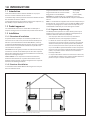
1.1 Introduction
The #HTK-EXT Exterior Heat Transfer Kit is designed to remove
unwanted heat from your home.
The following model(s) allow a maximum installation of two heat
transfer kits: #CLW-72
The maximum of two heat transfer kits can consist of up to (2) #HTK-
INT, (2) #HTK-EXT, or one of each.
1.2 Approvals
The exible ducts used with the #HTK-EXT feature are manufactured
and marked to the requirements of UL-181, Class 1 air duct.
1.3 Installation
1.3.1 Installation Precautions
This device must be installed by a qualied installer in accordance
with these instructions and in accordance with local codes, if any, and
with National Electrical Code ANSI/NFPA 70, current edition.
The #HTK-EXT fan will generate sound during operation. The eects
of the increased sound level can be minimized with careful planning
during installation of the system.
CAUTION: Wear protective gloves and safety glasses during
installation. Sheet metal edges are sharp.
Disconnect electrical power supply before performing any
maintenance, repair, or electrical wiring.
WARNING: Failure to install, operate, and maintain the heat transfer
system - exterior in accordance with manufacturer's instructions will
result in conditions which may produce bodily injury and/or property
damage.
1.3.2 Installation Guidelines
The discharge outlet of the #HTK-EXT must be directed down to
prevent water inltration.
Minimum Duct Run Length: 3 ft (914mm)
Maximum Duct Run Length: 25 ft (7.8m)
Clearance to exible duct: 0 in
IMPORTANT: The insulated exible pipe is zero clearance to combustibles
but CANNOT be compressed into a smaller diameter.
NOTE: Support duct at intervals of no greater than 4 feet, with no
more than 1/2" sag between supports as required by local code. Do
not substitute any other duct work as a replacement for the provided
insulated exible duct.
1.3.3 Painting Requirements
The #HTK-EXT may be painted to a desired color, as long as the paint
selected has sucient temperature and environmental ratings.
• Thoroughly sand the existing coating prior to painting with
sandpaper or steel wool.
• The front of the cap cover may be eld-painted and cured up to
400 degrees Fahrenheit (204° C). All remaining parts of the cap
may be painted but they may not be cured beyond 190°F (88°C)
due to gaskets and components overheating.
• Certain areas of the cap surface may reach up to 600° F (316°C).
Paints selected should have sucient temperature ratings.
• Cap contains silicone sealant which could aect adherence of
paint. Please advise local painter of silicone content.
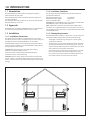
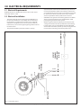
1.0 INTRODUCTION
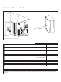
Figure 1.1, Possible Air Duct Locations/Terminations

4 Hussong Mfg. Co., Inc. • Kozy Heat Fireplaces Heat Transfer Kit - Exterior #HTK-EXT
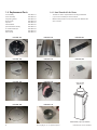
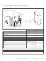
1.4 Replacement Parts
Fan Assembly HTK-EXT-101
Cover Assembly HTK-EXT-102
Vinyl Siding Shield HTK-EXT-103
Electrical Box HTK-EXT-104
Capacitor HTK-EXT-105
Terminal Block HTK-EXT-106
Speed Control Assembly HTK-EXT-107
6" Insulated Flex Pipe HTK-EXT-108
Band Clamp HTK-EXT-109
HTK 6" Collar HTK-EXT-110
HTK-EXT-109
HTK-EXT-108
HTK-EXT-105
HTK-EXT-102
HTK-EXT-104
HTK-EXT-101
HTK-EXT-107
HTK-EXT-106
HTK-EXT-103
HTK-EXT-110
HTK 6” COLLAR
#HTK-EXT-110
HTK AIR CHUTE (required for #HTK-EXT)
1.4.1 Heat Transfer Kit Air Chute
• The HTK air chute is required when installing a #HTK-EXT.
• (1) air chute is needed per heat transfer kit.
• Order model specic air chute. Yours may look dierent than
what is shown.

Heat Transfer Kit - Exterior #HTK-EXT R.1 Hussong Mfg. Co., Inc. • Kozy Heat Fireplaces 5
2.0 INSTALLATION
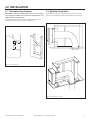
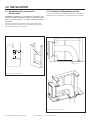
2.1 Termination Cap Framing
IMPORTANT: Termination framing MUST be level so the termination
cap is level upon installation. This is required so precipitation does not
build up inside the termination cap.
Find desired location of exterior heat transfer kit termination. For
horizontal termination cap clearances, see Figure 2.3.
2.2 Rooftop Termination
If the #HTK-EXT is going to terminate on a at roof, an enclosure
similar to the one shown in Figure 2.2 will need to be constructed.
10”
(254mm)
13
½”
(343mm)
Figure 2.1, Framing Dimensions
12”
(305mm)
Figure 2.2, Rooftop Enclosure Framing

6 Hussong Mfg. Co., Inc. • Kozy Heat Fireplaces Heat Transfer Kit - Exterior #HTK-EXT R.1
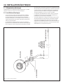
A
F
L
B
B
J
D
E
H
I
C
G
K
Figure 2.3, Minimum Termination Cap Clearances
2.3 Horizontal Termination Cap Clearances
36”
(914mm)
Canadian installations US installations
A Clearance above grade, veranda, porch, deck, or balcony 12 in (30 cm) 12 in (30 cm)
B Clearance to window or door that may be opened 12 in (30 cm) 9 in (23 cm)
C Clearance to permanently closed window (recommended to prevent condensation on
window)
12 in (30 cm)* 12 in (30 cm)*
D Vertical clearance to ventilated sot located above the terminal within a horizontal
distance of 2 feet (61 cm) from the center line of the terminal
0 in (0 cm)* 0 in (0 cm)*
E Clearance to unventilated sot 0 in (0 cm)* 0 in (0 cm)*
F Clearance to outside corner 0 in (0 cm)* 0 in (0 cm)*
G Clearance to inside corner 12 in (30 cm)* 12 in (30 cm)
H Clearance to each side of center line extended above meter/regulator assembly 3 ft (91 cm) within a height
15 ft (4.5 m) above the meter/
regulator assembly
*
I Clearance to service regulator vent outlet 3 ft (91 cm) *
J Clearance above paved sidewalk or paved driveway located on public property 7 ft (2.13 m)† *
K Clearance under veranda, porch deck, or balcony 0 in (0cm)‡ 0 in (0 cm)
L Clearance between two horizontal terminations 12 in (30 cm) 12 in (30 cm)
* Clearance in accordance with local installation codes and the requirements of the gas supplier.
† A vent shall not terminate directly above a sidewalk or paved driveway that is located between two single family dwellings and serves both dwellings.
‡ Permitted only if veranda, porch, deck, or balcony is fully open on a minimum of two sides beneath the oor.
VINYL SOFFIT, VINYL CEILING, AND VINYL OVERHANG DISCLAIMER: Clearances to heat resistant material (i.e. wood, metal). This does not include vinyl. Hussong
Manufacturing Co., Inc. will not be held responsible for heat damage caused from terminating under vinyl overhangs, vinyl ceilings, or vinyl ventilated/unventi-
lated sots.

Heat Transfer Kit - Exterior #HTK-EXT R.1 Hussong Mfg. Co., Inc. • Kozy Heat Fireplaces 7
2.4 Installation Instructions
NOTE: A #HTK-FEK Finishing Extension Kit will be needed for
installations with exterior nishing materials greater than 1" thick.
Order with the appliance and venting system. It will be used to ensure
that the nishing is done to appropriate size for the #HTK-FEK to be
installed properly.
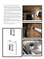
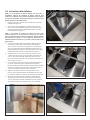
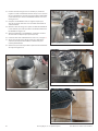
1. Remove the cover assembly (6) screws for installation of the
#HTK-EXT base. See Figure 2.4.
2. Remove the shipping bracket by removing (2) screws on the
backside of the assembly (Figure 2.5). Remove the two screws
that attach the bracket to the inside of the HTK-EXT assembly
(Figure 2.6). Discard shipping bracket (Figure 2.7).
NOTE: If you are using exterior nishing material thicker than 1"
(such as stone) then you will need to use #HTK-EXT-FEK Heat Transfer
Finishing Extension Kit. Start with Step 3. If installing the #HTK-EXT
with 1" or less nishing material, proceed to Step 8 on the next page.
3. Place FEK box over the framed opening in the wall. Ensure the
FEK is level to ensure precipitation does not build up in the HTK-
EXT termination cap when it is installed. Attach it to the building.
Verify the box remains square so the HTK-EXT can be installed
correctly. See Figure 2.8.
4. Seal all corners, joints, and bend lines with silicone (with a
minimum 300°F continuous exposure rating) caulk. Ensure all
gaps and holes are lled so a sealed envelope is formed. See
Figure 2.9 and Figure 2.10.
5. The wall is now ready to be nished. Finishing materials such as
stone, marble, or brick can then be applied up to the anges of
the #HTK-FEK that protrude perpendicular to the wall. This will
ensure that the cap will t into the opening after nishing has
been completed.
6. NOTE: Outside anges of the#HTK-FEK must not have any
pressure on them from the nishing materials. This could cause
the opening left after nishing to be too small.
7. After the #HTK-FEK has been installed and the nishing of the
wall is completed, apply a bead of silicone (with a minimum of
300°F continuous exposure rating) to the #HTK-FEK around the
entire metal ange where it would make contact with the #HTK-
EXT.
Figure 2.4, Remove Cover Assembly
Figure 2.5, Remove (2) Screws on Backside of Assembly
Figure 2.6, Remove (2) Screws Securing Bracket on the Inside
Figure 2.7, Discard Shipping Bracket

8 Hussong Mfg. Co., Inc. • Kozy Heat Fireplaces Heat Transfer Kit - Exterior #HTK-EXT R.1
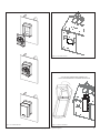
Figure 2.8, FEK Installed on Wall
Figure 2.9, Silicone Corners
Figure 2.10, Silicone Perimeter
8. —If you are using a FEK, align the #HTK-EXT base with FEK
ensuring the cap is level. Apply a bead of silicone (with a
minimum 300°F continuous exposure rating) around the entire
metal ange of the #HTK-EXT. See Figure 2.11 and Figure 2.12.
—If you are securing the HTK-EXT base directly to the wall, place
a bead of silicone (with a minimum 300°F continuous exposure
rating) on the backside of the mounting ange for the HTK-EXT.
See Figure 2.11 and Figure 2.12. Attach the HTK-EXT base to the
wall with the screws provided.
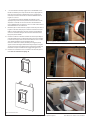
9. Remove (4) sheet metal screws securing the HTK cover plate.
Figure 2.13 is an example of a HTK cover plate on the CLW-72.
The location of the HTK cover plate might vary depending on the
model. Refer to your replace manual for this information.
10. Install the unit specic heat transfer kit air chute. Use the metal
screws provided in the kit to install the air chute to the replace.
Reference the included instructions in the unit specic HTK air
chute for your model.
When the air chute is installed, make sure the damper lays
against the outer shell of the replace when in resting position.
Ensure the damper will move freely when the fan is engaged. See
Figure 2.14.
11. Install the collar provided with the air chute using (4) sheet metal
screws. Instructions continue on page 10.
Figure 2.11, Silicone Rear

Heat Transfer Kit - Exterior #HTK-EXT R.1 Hussong Mfg. Co., Inc. • Kozy Heat Fireplaces 9
Figure 2.12, HTK-EXT FEK Install
CLW-72 AIR CHUTE & DAMPER SHOWN FOR REFERENCE ONLY.
YOUR AIR CHUTE AND DAMPER MAY LOOK DIFFERENT THAN ONE SHOWN.
Figure 2.13, Cover Plate Removal
Figure 2.14, Air Chute Installation

10 Hussong Mfg. Co., Inc. • Kozy Heat Fireplaces Heat Transfer Kit - Exterior #HTK-EXT R.1
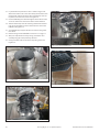
Figure 2.15, Band Clamp
Figure 2.16, Screws in Inner Liner
Figure 2.17, Liner Installed with Band Clamp
Figure 2.18, Vinyl Siding Installed
12. Lay the band clamp over the 6" collar as shown in Figure 2.15.
Attach the inside 6" liner to the collar with (3) sheet metal screws.
Use the band clamp to attach the outer insulated liner over the
top of the inner liner to the collar. See Figure 2.16.
13. Cut insulated ex pipe to desired length to reach from the collar
on the air chute to the collar on the exterior heat transfer kit.
14. Slide the band clamp over the remaining unattached insulated
liner. Use (3) sheet metal screws to attach the inner liner to the
HTK-EXT. See Figure 2.17.
15. Secure exible pipe. Support the duct at intervals of no greater
than 4 feet.
16. Run the wiring into the #HTK-EXT. See Section 3.0 on page 11.
17. After you complete the necessary wiring, reinstall the cover
assembly using (6) screws previously removed.
18. Use (3) provided screws to attach the vinyl siding shield. See
Figure 2.18.

Heat Transfer Kit - Exterior #HTK-EXT R.1 Hussong Mfg. Co., Inc. • Kozy Heat Fireplaces 11
3.0 ELECTRICAL REQUIREMENTS
3.1 Electrical Requirements
#HTK-EXT operates on 120VAC, 60hz electrical service. The current
draw of this device is 1.72A.
3.2 Electrical Installation
• The point of entry for electrical wiring into the #HTK-EXT is on
the rear of the termination cap assembly. If you are mounting
the termination cap before electrical work can be completed,
verify there is enough space for access to the back side of the
termination cap to run the wiring through the grommet and into
the electrical box.
• The provided on/o fan speed control switch is the only
approved speed control switch for this device. If you choose to
not use the provided fan speed control switch, you may wire in
an on/o switch of your choice, but you cannot wire in any other
fan speed control. Ensure any other chosen switch meets the
electrical requirements of the system listed in Section 3.1.
• #HTK-EXT fan will generate sound during operation. The eects
of the increased sound level can be minimized with careful
planning during installation of the system.
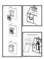
• When wiring the provided on/o fan speed control, the leads
coming out the switch will intercept with the hot wire leading
from the power source to the #HTK-EXT. Inside the #HTK-EXT
electrical box there will be (1) black, (1) white, and (1) green wire
leads to attach to the wiring ran from the power source.
WIRE NUTS
BLACK
WHITE
GROUND
BLUE
BLACK
BROWN
GREEN/BLUE
POWER SOURCE
ON/OFF-
FAN SPEED
CONTROL
SWITCH
CAPACITOR
TERMINAL
BLOCK
FAN
Figure 3.1, HTK-EXT Wiring Diagram


HUSSONG MANUFACTURING CO., INC.
LISEZ TOUTES CES ÉTAPES
AVANT DE COMMENCER L’INSTALLATION.
LAISSEZ CE MANUEL AVEC L’APPAREIL.
Ce kit doit être installé par un centre de service
ou un installateur qualié, ou par le fournisseur
de gaz, au moment d’installer l’appareil de
chauffage. Ces instructions doivent être utilisées
conjointement avec le manuel d’installation
et d’utilisation fourni avec l’appareil. Veuillez
lire complètement le manuel d’installation de
l’appareil avant de commencer les procédures
de ce manuel d’instructions.
INSTALLATEUR : Laissez ce manuel avec l’appareil.
PROPRIÉTAIRE : Conservez ce manuel pour le consulter.
1.0 INTRODUCTION .......................................................................3
1.1 Introduction ......................................................................................... 3
1.2 Produit approuvé ............................................................................... 3
1.3 Installation ............................................................................................ 3
1.4 Pièces de rechange............................................................................4
2.0 INSTALLATION .........................................................................5
2.1 Encadrement de terminaison d'évacuation .............................5
2.2 Terminaison d'évacuation au toit .................................................5
2.3 Dégagements du chapeau d'évacuation horizontal .............6
2.4 Instructions d'installation ............................................................... 7
3.0 INSTALLATION ÉLECTRIQUE ................................................ 11
3.1 Alimentation électrique ...............................................................11
3.2 Installation électrique ....................................................................11
English and French installation manuals are available through your
local dealer. Visit our website www.kozyheat.com.
Les manuels d’installation en français et en anglais sont disponibles
chez votre détaillant local. Visitez
www.kozyheat.com
.
KIT DE TRANSFERT DE
CHALEUR EXTÉRIEUR
nº HTK-EXT
Hussong Manufacturing Co., Inc.
P.O. Box 577, 204 Industrial Park Drive
Lakeeld, MN 56150-0577, USA
Kit de transfert de chaleur - Extérieur nº HTK-EXT
Rév. 2, 9/19
Pour utilisation avec modèles CLW-40 et CLW-72


Kit de transfert de chaleur extérieur HTK-EXT Hussong Mfg. Co., Inc. • Kozy Heat Fireplaces 3
1.1 Introduction
Le Kit de transfert de chaleur extérieur HTK-EXT est conçu pour
évacuer la chaleur indésirable de votre maison.
Le modèle de foyer suivant permet une installation maximale de deux
kits de transfert de chaleur : CLW-72
Le maximum de deux kits de transfert de chaleur peut comporter : (2)
kits HTK-INT, ou (2) kits HTK-EXT, ou un de chaque.
1.2 Produit approuvé
Les conduits exibles utilisés avec le HTK-EXT sont fabriqués et
marqués aux exigences de la norme UL-181, Conduits d’air de Classe 1.
1.3 Installation
1.3.1 Précautions d'installation
Ce système doit être installé par un installateur qualié selon ces
instructions et les codes locaux, et le Code canadien de l’électricité
CSA C22.1 (ou le National Electrical Code ANSI/NFPA 70, aux É.-U.).
Le ventilateur du HTK-EXT fera du bruit, une fois en marche. Les eets
du niveau sonore accru peuvent être minimisés en planiant avec
soin l’installation du système.
ATTENTION: Porter des gants protecteurs et lunettes de sécurité pour
l’installation. Les bords en tôle métallique ont des arêtes coupantes.
Débranchez l’alimentation électrique avant d’eectuer tout entretien,
réparation ou câblage électrique.
AVERTISSEMENT: Le non-respect des instructions d’installation,
d’utilisation et d’entretien de ce système de transfert de chaleur
extérieur pourrait créer des conditions dangereuses avec risques de
blessures et de dommages matériels.
1.3.2 Directives d'installation
La sortie d'évacuation du HTK-EXT doit être dirigée vers le bas pour
éviter une infiltration d'eau..
Longueur minimale de course du conduit: 3 pi (914mm)
Longueur maximale de course du conduit: 25 pi (7,8m)
Dégagement au conduit exible: 0 pouces (0mm)
IMPORTANT: Le conduit exible isolé est à dégagement zéro aux
matériaux combustibles mais NE PEUT PAS être comprimé à un diamètre
inférieur.
NOTE: Le conduit doit être supporté à des intervlles ne dépassant pas
4 pieds (122 cm), avec pas plus de 1/2 po (13 mm) de déexion entre
les supports, tel qu’exigé par les codes locaux. Ne remplacez pas le
conduit exible isolé fourni par aucun autre type de conduit.
1.3.3 Exigences de peinturage
Le HTK-EXT peut être peinturé à la couleur désirée, pourvu que la
peinture choisie ait une résistance susante aux températures et
conditions ambiantes extérieures (intempéries).
• Avec du papier sablé ou de la laine d’acier, sablez bien le
revêtement existant, avant d’appliquer la peinture.
• Le devant du couvercle du chapeau d’évacuation peut être
peinturé sur place en faisant sécher la peinture à 400°F (204°C).
Toutes les autres pièces du chapeau peuvent être peinturées,
mais on ne doit pas les faire sécher à plus de 190°F (88°C) pour
ne pas surchauer les joints d’étanchéité et autres composants.
• Certaines surfaces du chapeau peuvent atteindre jusqu’à 600°F
(316C°). Les peintures choisies doivent avoir une résistance
thermique susante.
• Le chapeau d’évacuation contient un scellant à base de silicone,
qui peut aecter l’adhérence de la peinture. Veuillez informer le
peintre local que ce scellant contient du silicone..
1.0 INTRODUCTION
Figure 1.1, Emplacements possibles des conduits d'air et des chapeaux d'évacuation

4 Hussong Mfg. Co., Inc. • Kozy Heat Fireplaces Kit de transfert de chaleur extérieur HTK-EXT
1.4 Pièces de rechange
Ensemble de ventilateur HTK-EXT-101
Couvercle HTK-EXT-102
Protecteur de revêtement de vinyle HTK-EXT-103
Boîte électrique HTK-EXT-104
Condensateur HTK-EXT-105
Bornier de connexion HTK-EXT-106
Contrôle de vitesse HTK-EXT-107
Conduit exible isolé 6 po HTK-EXT-108
Collier de serrage HTK-EXT-109
Raccord 6 po du HTK HTK-EXT-110
HTK-EXT-109
HTK-EXT-108
HTK-EXT-105
HTK-EXT-102
HTK-EXT-104
HTK-EXT-101
HTK-EXT-107
HTK-EXT-106
HTK-EXT-103
HTK-EXT-110
RACCORD 6 po HTK
#HTK-EXT-110
CHUTE D’AIR DU HTK
(requise pour HTK-EXT)
1.4.1 Heat Transfer Kit Air Chute
• The HTK air chute is required when installing a #HTK-EXT.
• (1) air chute is needed per heat transfer kit.
• Order model specic air chute. Yours may look dierent than
what is shown.

Kit de transfert de chaleur extérieur HTK-EXT Hussong Mfg. Co., Inc. • Kozy Heat Fireplaces 5
2.0 INSTALLATION
2.1 Encadrement de terminaison
d'évacuation
IMPORTANT: L'encadrement de la terminaison d'évacuation DOIT
être de niveau pour que le chapeau installé soit de niveau. Ceci pour
éviter que de l'eau de pluie ne s'accumule à l'intétieur du hapeau
d'évacuation.
Déterminez l’emplacement désiré du chapeau d’évacuation du kit
de transfert de chaleur extérieur. Pour les dégagements du chapeau
d’évacuation horizontal, voir la Figure 2.3.
2.2 Terminaison d'évacuation au toit
Si le chapeau d’évacuation du HTK-EXT sera situé sur un toit plat, une
enceinte similaire à celle illustrée à la Figure 2.2 devra être construite.
10”
(254mm)
13
½”
(343mm)
Figure 2.1, Dimensions d'encadrement
12”
(305mm)
Figure 2.2, Encadrement de l'enceinte au toit

6 Hussong Mfg. Co., Inc. • Kozy Heat Fireplaces Kit de transfert de chaleur extérieur HTK-EXT
A
F
L
B
B
J
D
E
H
I
C
G
K
Figure 2.3, Dégagements minimums du chapeau d'évacuation
2.3 Dégagements du chapeau d'évacuation horizontal
36”
(914mm)
Installations au Canada Installations aux É.-U.
A Dégagement au-dessus d'un terrain, véranda, galerie, terrasse ou balcon 12 po (30 cm) 12 po (30 cm)
B Dégagement à une porte ou fenêtre ouvrante 12 po (30 cm) 9 po (23 cm)
C Dégagement à une porte ou fenêtre fermée en permanence (pour éviter de la conden-
sation sur la fenêtre)
12 po (30 cm)* 12 po (30 cm)*
D Dégagement vertical à un sote ventilé situé au-dessus du chapeau d'évacuation en-
deçà d'une distance horizontale de 2 pieds (61 cm) du centre du chapeau d'évacuation
0 po (0 cm)* 0 po (0 cm)*
E Dégagement à un sote non ventilé 0 po (0 cm)* 0 po (0 cm)*
F Dégagement à un coin extétieur 0 po (0 cm)* 0 po (0 cm)*
G Dégagement à un coin intérieur 12 po (30 cm)* 12 po (30 cm)
H Dégagements de chaque côté du centre projeté au-dessus d'un compteur/régulateur
de gaz
3 pieds(91 cm) du centre à une
hauteur de 15 pieds (4,5m) au-
dessus du compteur/rég.
*
I Dégagement à la sortie d'évent du régulateur de gaz 3 pi (91 cm) *
J Dégagement au-dessus d'un trottoir pavé ou entrée d'auto pavée, situés sur un terrain
public
7 pi (2.13 m)† *
K Dégagement sous un(e) véranda, galerie, terrasse ou balcon 12 po (30 cm)‡ 12 po (30 cm)
L Dégagement entre deux terminaisons d'évacuation horizontales 12 po (30 cm) 12 po (30 cm)
* Les dégagements doivent être conformes aux codes d'installation locaux et aux exigences du fournisseur de gaz.
† L'évacuation ne peut pas se terminer au-dessus d'un trottoir ou entrée d'auto pavée situés entre (2) havitations familiales imples et desservant les 2 habitations
‡ Permis seulement si la véranda, la galerie, la terrasse ou le balcon sont complètement ouverts au moins aux deux côtés sous le plancher
AVIS DE NON-RESPONSABILITÉ - SOFFITES EN VINYLE, PLAFONDS EN VINYLES ET AVANT-TOITS EN VINYLE : Dégagements aux matériaux résistant à la chaleur (ex.
bois, métal). Ceci n'inclut pas le vinyle. Hussong Manufacturing Co., Inc. pas responsable des dommages dus à la chaleur si la terminaison (conduit) d'évacuation
aboutit sous un avant-toit (ex. corniche) en vinyle, un plafond en vinyle ou un sote (ventilé ou non ventilé) en vinyle

Kit de transfert de chaleur extérieur HTK-EXT Hussong Mfg. Co., Inc. • Kozy Heat Fireplaces 7
2.4 Instructions d'installation
NOTE: Un kit d'extensin de nition HTK-FEK sera nécessaire si
l'installation comporte des matériaux de nition extérieure dont
l'épaisseur est supérieure à 1 po (25mm). Commandez-le avec le kit HTK
et le système d'évacuation. Cela permettra d'assurer les dimensions de
nition adéquates pour installer le HTK.
1. Retirez les (6) vis du couvercle pour l’installation de la base du
HTK-EXT. Voir Figure 2.4.
2. Pour retirer la bride d’expédition, commencez par retirer les
(2) vis à l’arrière du HTK-EXT (Figure 2.5). Puis, retirez les (2) vis
retenant la bride à l’intérieur du HTK-EXT (Figure 2.6). Jetez la
bride d’expédition (Figure 2.7).
NOTE: Si vous utilisez un matériau de nition extérieure d'une
épaisseur supérieure à 1 po (25 mm) (p.ex. de la pierre), vous devrez
utiliser let Kit d'extension de nition de transfert de chaleur HTK-EXT-
FEK. Commencez à l'étape 3. Si vous installez le HTK-EXT avec un
matériau de nition de moins de 1 po (25mm), sautez à l'étape 8 (à la
page suivante)
3. Placez la boîte du kit d’extension de nition (FEK) par-dessus
l’ouverture encadrée dans le mur. Vériez que le kit FEK est
de niveau pour s’assurer que l’eau de pluie ne s’accumule pas
dans le chapeau d’évacuation du HTK-EXT installé. Fixez-la au
bâtiment. Vériez que la boîte reste perpendiculaire pour que le
HTK-EXT puisse être installé correctement. Voir Figure 2.8.
4. Calfeutrez tous les coins, joints et lignes de contour avec du
scellant à base de silicone (ayant une résistance minimale de
300°F en exposition continue). Vériez que tous les trous et
fentes sont remplis pour former une enveloppe scellée étanche.
Voir les Figure 2.9 et 2.10.
5. Le mur est maintenant prêt à recevoir les matériaux de nition
(ex. pierre, marbre ou brique), qui peuvent être appliqués
jusqu’aux brides du HTK-FEK qui dépassent perpendiculairement
du mur. Ceci permet de s’assurer que le chapeau d’évacuation
s’insérera bien dans l’ouverture, une fois le mur ni.
6. NOTE: Les matériaux de nition ne doivent exercer aucun
pression sur les brides extérieures du HTK-FEK, pour éviter que
les matériaux de nition installés ne rétrécissent trop l’ouverture.
7. Après avoir installé le HTK-FEK et terminé la nition du mur,
appliquez un joint de silicone (d’une résistance minimale de
300°F en exposition continue) au HTK-FEK sur tout le pourtour
de la bride en métal, aux points de contact avec le HTK-EXT.
Figure 2.4, Retirez le couvercle
Figure 2.5, Retirez les (2) vis à l'arrière du couvercle (du chapeau)
Figure 2.6, Retirez les (2) vis retenant la bride à l'intérieur
Figure 2.7, Jetez la bride d'expédition

8 Hussong Mfg. Co., Inc. • Kozy Heat Fireplaces Kit de transfert de chaleur extérieur HTK-EXT
Figure 2.8, FEK installé au mur
Figure 2.9, Appliquez le scellant silicone aux coins
Figure 2.10, Appliquez le scellant silicone tout autour (en périphérie)
8. —Si vous utilisez un kit FEK, alignez la base du HTK-EXT avec le
kit FEK en vériant que le chapeau est de niveau. Appliquez un
joint de silicone (résistance minimale de 300°F en exposition
continue) tout autour de la bride en métal du HTK-EXT. Voir les
Figures 2.11 et 2.12.
—Si vous xez la base du kit HTK-EXT directement au mur,
appliquez un joint de silicone (résistance minimale de 300°F en
exposition continue) sur la face arrière de la bride de xation
pour le HTK-EXT. Voir les Figures 2.11 et 2.12. Fixez au mur la base
du kit HTK-EXT avec les vis fournies.
9. Retirez les (4) vis à tôle retenant la plaque-couvercle pour HTK. La
Figure 2.13 montre cette plaque-couvercle installée sur le foyer
CLW-72. L’emplacement de la plaque-couvercle pour HTK peut
varier avec le modèle de foyer. Voir le manuel d’installation du
foyer pour plus de détails.
10. Installez la chute d’air du kit de transfert de chaleur spécique à
votre foyer. Utilisez les vis à tôle fournies dans le kit pour installer
la chute d’air au foyer. Voir les instructions fournies avec la chute
d’air du HTK spécique à votre modèle de foyer.
Une fois la chute d’air installée, vériez que le registre (volet)
appuie contre l’enveloppe extérieure du foyer lorsque le registre
est en position de repos. Vériez que le registre peut se déplacer
librement lorsque le ventilateur est engagé. Voir Figure 2.14.
11. Installez le raccord fourni avec la chute d’air en utilisant (4) vis à
tôle. Suite des instructions à la page 10.
Figure 2.11, Appliquez le scellant silicone sur la face arrière
La page est en cours de chargement...
La page est en cours de chargement...
La page est en cours de chargement...
La page est en cours de chargement...
-
 1
1
-
 2
2
-
 3
3
-
 4
4
-
 5
5
-
 6
6
-
 7
7
-
 8
8
-
 9
9
-
 10
10
-
 11
11
-
 12
12
-
 13
13
-
 14
14
-
 15
15
-
 16
16
-
 17
17
-
 18
18
-
 19
19
-
 20
20
-
 21
21
-
 22
22
-
 23
23
-
 24
24


Kozyheat Callaway 40 Le manuel du propriétaire
- Catégorie
- Cheminées
- Taper
- Le manuel du propriétaire
dans d''autres langues
- English: Kozyheat Callaway 40 Owner's manual
Documents connexes
-
Kozyheat Callaway See-Thru Le manuel du propriétaire
-
-
-
-
-
-
-
-