Fujitsu RCA18URTA-S Guide d'installation
- Catégorie
- Climatiseurs split-system
- Taper
- Guide d'installation

INDOOR UNIT (Cassette Type)
INSTALLATION MANUAL
For authorized service personnel only.
AIR CONDITIONER
English
PART No. 9381798025
Refer to the rating label with the serial number.
MADE IN THAILAND

En-1
1. SAFETY PRECAUTIONS
Be sure to read this manual thoroughly before installation.
The warnings and precautions indicated in this Manual contain important information
pertaining to your safety. Be sure to observe them.
Hand this Manual, together with the operating manual, to the customer. Request the
customer to keep them on hand for future use, such as for relocating or repairing the unit.
WARNING
Indicates a potentially or imminently hazardous situation which,
if not avoided, could result in death or serious injury.
Installation of this product must be done by experienced service technicians or profes-
sional installers only in accordance with this manual. Installation by nonprofessional or
improper installation of the product may cause serious accidents such as injury, water
leakage, electric shock, or ¿re. If the product is installed in disregard of the instructions
in this manual, it will void the manufacturer’s warranty.
Do not turn on the power until all work has been completed. Turning on the power be-
fore the work is completed can cause serious accidents such as electric shock or ¿re.
If refrigerant leaks when you are working, ventilate the area. If the leaking refrigerant
is exposed to a direct Àame it may produce a toxic gas.
Do not use this equipment with air or any other unspeci¿ed refrigerant in the refriger-
ant lines. Excess pressure can cause a rupture.
Installation must be performed in accordance with regulations, codes, or standards for
electrical wiring and equipment in each country, region, or the installation place.
This appliance is not intended for use by persons (including children) with reduced
physical, sensory or mental capabilities, or lack of experience and knowledge, unless
they have been given supervision or instruction concerning use of the appliance by a
person responsible for their safety. Children should be supervised to ensure that they
do not play with the appliance.
CAUTION
Indicates a potentially hazardous situation that may result in
minor or moderate injury or damage to property.
Read carefully all safety information written in this manual before you install or use the
air conditioner.
Install the product by following local codes and regulations in force at the place of instal-
lation, and the instructions provided by the manufacturer.
This product is part of a set constituting an air conditioner. The product must not be
installed alone or be installed with non-authorized device by the manufacturer.
Always use a separate power supply line protected by a circuit breaker operating on all
wires with a distance between contact of 3 mm for this product.
To protect the persons, earth (ground) the product correctly, and use the power cable
combined with an Earth Leakage Circuit Breaker (ELCB).
This product is not explosion proof, and therefore should not be installed in explosive
atmosphere.
Do not touch the ¿ns of the heat exchanger. Touching the heat exchanger ¿ns could
result in damage to the ¿ns or personal injury such as skin rupture.
To avoid getting an electric shock, never touch the electrical components soon after the
power supply has been turned off. After turning off the power, always wait 5 minutes or
more before you touch the electrical components.
This product contains no user-serviceable parts. Always consult experienced service
technicians for repairing.
When moving or relocating the air conditioner, consult experienced service technicians
for disconnection and reinstallation of the product.
Do not place any other electrical products or household belongings under the product.
Condensation dripping from the product might get them wet, and may cause damage or
malfunction to the property.
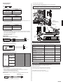
2. ABOUT THIS PRODUCT
2. 1. Special tools for R410A
Tool name Change from R22 to R410A
Gauge manifold
Pressure is high and cannot be measured with a R22
gauge. To prevent erroneous mixing of other refrigerants,
the diameter of each port has been changed.
It is recommended to use gauge with seals -0.1 to 5.3 MPa
(-1 to 53 bar) for high pressure.
-0.1 to 3.8 MPa (-1 to 38 bar) for low pressure.
Charge hose
To increase pressure resistance, the hose material and base
size were changed. (R410A)
Vacuum pump
A conventional vacuum pump can be used by installing a
vacuum pump adapter.
(Use of a vacuum pump with a series motor is prohibited.)
Gas leakage detector Special gas leakage detector for HFC refrigerant R410A.
Copper pipes
It is necessary to use seamless copper pipes and it is desirable that the amount of residual
oil is less than 40 mg/10 m. Do not use copper pipes having a collapsed, deformed or
discolored portion (especially on the interior surface). Otherwise, the expansion value or
capillary tube may become blocked with contaminants.
As an air conditioner using R410A incurs pressure higher than when using R22, it is neces-
sary to choose adequate materials.
WARNING
Use speci¿ed R410A piping only. For indoor units, use R410A Àare less joint nut assy
only. For outdoor units, use R410A Àare nuts only.
Use of pipes, Àare less nuts or Àare nuts other than speci¿ed, may cause product
malfunction, burst piping, or injury due to high internal pressure of the refrigerant cycle
caused by any inÀow air.
Use (re¿ll or replace with) speci¿ed refrigerant (R410A) only. Use of unspeci¿ed refrig-
erant can cause product malfunction, burst, or injury.
Do not mix any gas or impurities except speci¿ed refrigerant (R410A). InÀow of air or
application of unspeci¿ed material makes the internal pressure of the refrigerant cycle
too high, and may cause product malfunction, burst of piping, or injury.
2. 2. Accessories
WARNING
For installation purposes, be sure to use the parts supplied by the manufacturer or
other prescribed parts.
The use of non-prescribed parts can cause serious accidents such as the unit falling,
water leakage, electric shock, or ¿re.
The following installation parts are furnished. Use them as required.
Keep the installation manual in a safe place and do not discard any other accessories
until the installation work has been completed.
1. SAFETY PRECAUTIONS ……………………………………………………………… 1
2. ABOUT THIS PRODUCT ………………………………………………………………… 1
2.1. Special tools for R410A …………………………………………………………… 1
2.2. Accessories ………………………………………………………………………… 1
2.3. Optional parts ……………………………………………………………………… 2
3. GENERAL SPECIFICATION …………………………………………………………… 2
3.1. Selecting the pipe material ………………………………………………………… 2
3.2. Pipe requirement …………………………………………………………………… 2
3.3. Electrical requirement ……………………………………………………………… 3
4. INSTALLATION WORK ………………………………………………………………… 3
4.1. Selecting an installation location ………………………………………………… 3
4.2. Installation dimension ……………………………………………………………… 3
4.3. Installing the unit …………………………………………………………………… 3
4.4. Installing the drain pipe …………………………………………………………… 4
5. PIPE INSTALLATION …………………………………………………………………… 5
5.1. Flare connection (pipe connection) ……………………………………………… 5
5.2. Installing heat insulation …………………………………………………………… 6
6. ELECTRICAL WIRING …………………………………………………………………… 6
6.1. Wiring method ……………………………………………………………………… 7
7. CASSETTE GRILLE INSTALLATION …………………………………………………… 9
8. REMOTE CONTROLLER INSTALLATION …………………………………………… 9
9. FUNCTION SETTING …………………………………………………………………… 9
9.1. Turning on the power ……………………………………………………………… 9
9.2. Setting method ……………………………………………………………………… 9
9.3. RC Sensor setting ………………………………………………………………… 9
9.4. Function Details …………………………………………………………………… 9
10. SPECIAL INSTALLATION METHODS ……………………………………………… 10
10.1. Setting the address ……………………………………………………………… 10
10.2. Setting the DIP switch …………………………………………………………… 11
10.3. Group control …………………………………………………………………… 11
11. OPTION AND OTHER CONNECTABLE DEVICES ………………………………… 11
11.1. Optional parts …………………………………………………………………… 11
11.2. External input and output ……………………………………………………… 11
12. CHECK LIST …………………………………………………………………………… 12
13. TEST RUN ……………………………………………………………………………… 12
14. CUSTOMER GUIDANCE ……………………………………………………………… 13
15. ERROR CODES ……………………………………………………………………… 13
AIR CONDITIONER
INSTALLATION MANUAL
PART No. 9381798025
Indoor Unit (Cassette Type)
Contents
Note: This manual describes how to install the air conditioner described above. Handling
and installation shall only be done by professionals as outlined in this manual.

En-2
Name and Shape Q’ty Description
Installation manual
1
(This book)
Template
(Carton top)
1
For installing indoor unit
Washer
8
For installing indoor unit
Coupler heat insulation (Large)
1
For indoor side pipe joint (Gas pipe)
Coupler heat insulation (Small)
1
For indoor side pipe joint
(Liquid pipe)
Insulation
1
For installing drain pipe
Drain hose
1
For installing drain pipe
VP25 (O.D.32, I.D.25)
Hose Band
1
For installing drain hose
Drain hose heat insulation
1
For installing drain pipe
Cable tie (Large)
4
For connection pipe ¿xing.
Cable tie (Small)
2
Only one is used for this model.
Remote controller cable
1
For connecting the remote controller
2. 3. Optional parts
Parts name Model No. Summary
Wired Remote Controller UTY-RNR*Z1
For air conditioner operation
(2-wire type)
IR receiver unit UTY-LBT*C* For air conditioner operation
Wide panel UTG-AKXA-W
Wide panel hides the gap
between the ceiling hole and
the Cassette grille.
Panel spacer UTG-BKXA-W
Installation in a space of 56
mm or greater is possible by
using panel spacer when the
height behind the ceiling is low.
Air outlet shutter plate UTR-YDZK
Install the plate at outlet when
carrying out 3-way direction
operation
Insulation kit for High
humidity
UTZ-KXRA
External input and output
PCB
UTY-XCSX
For connecting external
devices
External input and output
PCB box
UTZ-GXRA
For installing the External input
and output PCB
External connect kit UTY-XWZXZG For control output port
Communication kit UTY-TWRXZ1
For wired remote controller
(2-wire type)
3. GENERAL SPECIFICATION
3. 1. Selecting the pipe material
CAUTION
Do not use existing pipes.
Use pipes that have clean external and internal sides without any contamination which
may cause trouble during use, such as sulfur, oxide, dust, cutting waste, oil, or water.
It is necessary to use seamless copper pipes.
Material : Phosphor deoxidized seamless copper pipes
It is desirable that the amount of residual oil is less than 40 mg/10 m.
Do not use copper pipes that have a collapsed, deformed, or discolored portion (es-
pecially on the interior surface). Otherwise, the expansion valve or capillary tube may
become blocked with contaminants.
Improper pipe selection will degrade performance. As an air conditioner using R410A in-
curs pressure higher than when using conventional refrigerant, it is necessary to choose
adequate materials.
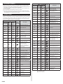
Thicknesses of copper pipes used with R410A are as shown in the table.
Never use copper pipes thinner than those indicated in the table even if they are available
on the market.
Pipe outside diameter [mm (in.)] Thickness [mm]
6.35 (1/4) 0.8
9.52 (3/8) 0.8
12.70 (1/2) 0.8
15.88 (5/8) 1.0
19.05 (3/4) 1.2
3. 2. Pipe requirement
CAUTION
Refer to the installation manual of the outdoor unit for description of the length of con-
necting pipe or for difference of its elevation.
Type
Diameter [mm (in.)]
Liquid Gas
18/25 6.35 (1/4) 15.88 (5/8)
40/50 9.52 (3/8) 19.05 (3/4)
Use pipe with water-resistant heat insulation.
CAUTION
Install heat insulation around both the gas and liquid pipes. Failure to do so may
cause water leaks.
Use heat insulation with heat resistance above 120 °C. (Reverse cycle model only)
In addition, if the humidity level at the installation location of the refrigerant piping is
expected to exceed 70 %, install heat insulation around the refrigerant piping.
If the expected humidity level is 70-80 %, use heat insulation that is 15 mm or thicker
and if the expected humidity exceeds 80 %, use heat insulation that is 20 mm or
thicker. If heat insulation is used that is not as thick as speci¿ed, condensation may
form on the surface of the insulation.
In addition, use heat insulation with heat conductivity of 0.045 W/(m·K) or less (at 20 °C).

En-3
(1) Locate where the air can be distributed evenly throughout the room by the unit.
(2) The inlet and outlet ports should not be obstructed; the air should be able to blow all
over the room.
(3) Leave the space required to service the air conditioner.
(4) Install the unit where connection to the outdoor unit is easy.
(5) Install the unit where the connection pipe can be easily installed.
(6) Install the unit where the drain pipe can be easily installed.
(7) Install the unit where noise and vibrations are not ampli¿ed.
(8) Take servicing, etc., into consideration and leave the spaces. Also install the unit where
the ¿lter can be removed.
(9) Do not install the unit where it will be exposed to direct sunlight.
Correct initial installation location is important because it is dif¿cult to move unit after it is
installed.
4. 2. Installation dimension
The ceiling rear height as shown in the ¿gure.
Strong and durable ceiling
3 or more
Floor
Obstruction
Unit: m
1.5 or
more
1.8 or more
1 or more
This product can be installed at a height of up to 4.2 m. However, if the heights of the
ceiling is higher than 3.2 m or lower than 2.7 m, it is necessary to set the position from
remote controller. (See 9. FUNCTION SETTING)
Discharge direction setting
Unit : mm
The discharge direction can be selected as shown below.
100 or more*
(4 directions) (3 directions)
* Please ensure suf¿-
cient service access
during installation.
For a 3-way outlet, make sure to perform the function setting on the remote control.
Also, make sure to use the optional shutter plate to block the outlet.
The ceiling height cannot be set in the 3-way outlet mode. Therefore, do not change the
setting in the setting the ceiling height. (See 9. FUNCTION SETTING)
When the outlet is shut, be sure to install the optional Air outlet shutter plate kit. For the
details of installation, please refer to installation manual of the kit.
4. 3. Installing the unit
WARNING
Carrying and installation of the unit should be performed by a suf¿cient number of
people and with suf¿cient equipment that is adequate for the weight of the unit. Per-
forming such work with an insuf¿cient number of people or with inadequate equipment
could result in dropping of the unit or personal injury.
If the job is done with the panel frame only, there is a risk that the unit will come loose.
Please take care.
When fastening the hangers, make the bolt positions uniform.
3. 3. Electrical requirement
The indoor unit is powered from the outdoor unit. Do not power indoor unit from separate
power source.
WARNING
Standard for electrical wiring and equipment differs in each country or region. Before you
start electrical working, con¿rm related regulations, codes, or standards.
Cable
Conductor size
(mm
2
)
Type
Remarks
Connection cable 1.5 (MIN.) Type 60245 IEC57 3Wire+Earth (Ground)
Max. Cable Length: Limit voltage drop to less than 2%. Increase cable gauge if voltage
drop is 2% or more.
Cable
Conductor size
(mm
2
)
Type
Remarks
Remote controller
cable
(3-wire type)
0.33
Sheathed PVC
cable
Polar 3 wire
Remote controller
cable
(2-wire type)
0.33 to 1.25
Sheathed PVC
cable
Non-polar 2 wire, twisted
pair
4. INSTALLATION WORK
WARNING
Do not turn on the power until all installation work is complete.
Carrying and installation of the unit should be performed by a suf¿cient number of
people and with suf¿cient equipment that is adequate for the weight of the unit.
Performing such work with an insuf¿cient number of people or with inadequate equip-
ment could result in dropping of the unit or personal injury.
CAUTION
For installation details, refer to the technical data.
4. 1. Selecting an installation location
Decide the mounting position together with the customer as follows.
WARNING
Select installation locations that can properly support the weight of the indoor unit
and which will not amplify sound or vibration. If the installation location is not strong
enough, the indoor unit may fall and cause injuries.
Install the units securely so that they do not topple or fall.
CAUTION
Do not install the indoor unit in the following areas:
Area with high salt content, such as at the seaside.
It will deteriorate metal parts, causing the parts to fall or the unit to leak water.
Area ¿lled with mineral oil or containing a large amount of splashed oil or steam,
such as a kitchen.
It will deteriorate plastic parts, causing the parts to fall or the unit to leak water.
Area that generates substances that adversely affect the equipment, such as sulfuric
gas, chlorine gas, acid, or alkali. It will cause the copper pipes and brazed joints to
corrode, which can cause refrigerant leakage.
Area that can cause combustible gas to leak, contains suspended carbon ¿bers or
Àammable dust, or volatile inÀammables such as paint thinner or gasoline. If gas
leaks and settles around the unit, it can cause a ¿re.
Area where animals may urinate on the unit or ammonia may be generated.
Do not use the unit for special purposes, such as storing food, raising animals, growing
plants, or preserving precision devices or art objects. It can degrade the quality of the
preserved or stored objects.
Do not install where there is the danger of combustible gas leakage.
Do not install the unit near a source of heat, steam, or Àammable gas.
Install the unit where drainage does not cause any trouble.
Install the indoor unit, outdoor unit, power supply cable, transmission cable, and remote
control cable at least 1 m away from a television or radio receivers. The purpose of this
is to prevent TV reception interference or radio noise.
(Even if they are installed more than 1 m apart, you could still receive noise under
some signal conditions.)
Install the unit where ambient temperature does not reach 60°C or more.
Take a measure such as ventilation for an environment in which heat is retained.
If children under 10 years old may approach the unit, take preventive measures so that
they cannot reach the unit.
Install the indoor unit on the place where the height from the Àoor is more than 1.8 m.

En-4
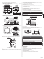
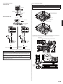
4.3.1. Position the ceiling hole and hanging bolts
(1) Positions of the ceiling opening, hanging bolt pitch, piping and ducts.
Ceiling opening and hanging bolt pitch.
Unit: mm
Type
Dimension (mm)
AB
18/25 246 256
40/50 288 298
950(Panel frame)
860 - 910(Ceiling opening)
768(Hanging bolt pitch)
840(Body frame)
860 - 910(Ceiling opening)
950(Panel frame)
840(Body frame)
796(Hanging bolt pitch)
20 - 45
20 - 45
50
200
20 - 45
20 - 45
130
130
130
130
200 - 205
39
10
A
B
50 - 100
Refrigerant piping and drain piping positions.
Unit: mm
Liquid pipe
293
45
342
200
140
180
80
Gas pipe
Drain pipe
(Connect the
attached drain
hose)
10
Distribution ducts and fresh air inlet positions.
Unit: mm
Distribution duct connecting port
Detailed diagram of distribution duct
connecting port (4 sides)
bolt pitch
Cut out
Cut out
95
232
114
100
100
83
83
352
90
163
163
Fresh air inlet position
10 ×
3.2 hole
4 ×
3.2 hole
Distribution duct
connecting port
Distribution duct connecting port
Distribution duct connecting port
Fresh air inlet
position
Drain pipe
Refrigerant pipe
Note:
Conduct proper insulation when connecting the distribution ducts and fresh air inlet.
Insulation
Fresh air inlet position
Note:
When introducing fresh air into the indoor unit, please remove the insulation af¿xed to the
drain pan.
(2) Setting the positions of hanging bolt and ceiling opening.
Use an installation template (packaging top surface) to set the positions of the hanging
bolt and ceiling opening and drill holes.
(3) Hanging structure.
Select a strong structure for the hanging location.
If necessary, reinforce the hanging bolt with quake proof columnar support material to
prevent shaking.
Use hanging bolts of M8-M10.
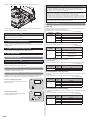
4.3.2. Body installation
(1) Install the attached washer and nut (prepared on site) onto the hanging bolt.
(2) Hook the body onto the hanging bolt.
(3) Adjust the dimensions of the ceiling surface from the body. After installing the Cassette
grille, you can make ¿ne adjustment of the height of the body. For details, refer to the
installation manual of the Cassette grille.
WARNING
Perform ¿nal tightening by tightening the double nut ¿rmly.
Be sure to install the body horizontally and adjust the height below the body and the
ceiling surface properly.
10~15
Hanging bolt (locally purchased)
Nut A (locally purchased)
Washer (Accessories)
After installing the body,
tighten the nuts.
Unit: mm
Washer (Accessories)
Nut B (Double Nut)
(locally purchased)
4.3.3. Leveling
Using a level, or vinyl hose ¿lled with water, ¿ne adjust so that the body is level.
Inclined installation so as the drain pipe side is higher may cause a malfunction of the Àoat
switch, and may cause water leakage.
Vinyl hoses
Drain pipe
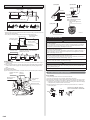
4. 4. Installing the drain pipe
WARNING
Do not insert the drain piping into the sewer where sulfurous gas occurs. (Heat ex-
change erosion may occur.)
Insulate the parts properly so that water will not drip from the connection parts.
Check for proper drainage after the construction by using the visible portion of transpar-
ent drain port and the drain piping ¿nal outlet on the body.
CAUTION
Do not apply adhesive agent on the drain port of the body. (Use the attached drain
hose and connect the drain piping.)
Install the drain pipe:
Install the drain pipe with downward gradient (1/50 to 1/100) and so there are no rises or
traps in the pipe.
Use general hard polyvinyl chloride pipe (VP25) [outside diameter 32 mm] and connect it
with adhesive (polyvinyl chloride) so that there is no leakage.
When the pipe is long, install supporters.
Do not perform air bleeding.
Always heat insulate the indoor side of the drain pipe.
If it is impossible to have suf¿cient gradient of pipe, perform drain lift-up.

En-5
Pipe size
Drain pipe VP25 (O.D. 32 mm)
Hanging ¿ttings
1.5 to 2 m
VP25 (O.D. 32 mm)
Downward gradient 1/100 to 1/50
Rise
PROHIBITED:
Trap
Air bleeding
When lifting up drain:
Height of inclined pipe should be less than 850 mm from the ceiling. A rise dimension over
this range will cause leakage.
Lift up the pipe vertically at the position of 300 mm or less from the unit.
300 mm or less
VP25 (O.D. 32 mm)
local arrangement
850 mm or less
Horizontal or
upward gradient
Downward gradient
1/100 to 1/50
VP30 (O.D. 38 mm) or more Downward
gradient 1/100 to 1/50
850 mm or less
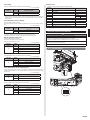
Working procedure
(1) Install the attached drain hose to the drain port of the body. Attach hose band on top of
the drain hose.
(2) Use vinyl adhesive agent to glue the drain piping (PVC pipe VP25) which is prepared
on site or elbow socket. (Apply color adhesive agent evenly until the gauge line and
seal.)
(3) Check the drainage.
(4) Install the heat insulation.
(5) Use the attached heat insulation to insulate the drain port and band parts of the body.
Install the knob faces
upward
Attached drain hose
heat insulation
Attached heat insulation
Attached
hose band
Locally arranged
vinyl pipe
Attached drain hose
(a) Top view
(c) Top view
(b) Side view
VP25
Applying area of
adhesive
35
4 or less
Gauge line
Hose band
5-10
20
Make sure there
are no gaps
Wind the attached heat insulation
around the hose band
(d) Hose opening view
Make sure the alignment is
on top
Unit: mm
5. PIPE INSTALLATION
WARNING
During installation, make sure that the refrigerant pipe is attached ¿rmly before you
run the compressor.
Do not operate the compressor under the condition of refrigerant piping not attached
properly with 2-way or 3-way valve open. This may cause abnormal pressure in the
refrigeration cycle that leads to breakage and even injury.
During the pump-down operation, make sure that the compressor is turned off before
you remove the refrigerant piping.
Do not remove the connection pipe while the compressor is in operation with 2-way or
3-way valve open. This may cause abnormal pressure in the refrigeration cycle that
leads to breakage and even injury.
When installing and relocating the air conditioner, do not mix gases other than the
speci¿ed refrigerant R410A to enter the refrigerant cycle.
If air or other gas enters the refrigerant cycle, the pressure inside the cycle will rise to
an abnormally high value and cause breakage, injury, etc.
If refrigerant leaks while work is being carried out, ventilate the area. If the refrigerant
comes in contact with a Àame, it produces a toxic gas.
CAUTION
Be more careful so that foreign matter (oil, water, etc.) does not enter the piping than
with refrigerant R410A models. Also, when storing the piping, securely seal the open-
ings by pinching, taping, etc.
While brazing the pipes, be sure to purge with dry nitrogen gas.
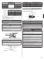
5. 1. Flare connection (pipe connection)
5.1.1. Flaring
Use special pipe cutter and Àare tool exclusive for R410A.
(1) Cut the connection pipe to the necessary length with a pipe cutter.
(2) Hold the pipe downward so that cuttings will not enter the pipe and remove any burrs.
(3) Insert the Àare nut (always use the Àare nut attached to the indoor and outdoor units
respectively) onto the pipe and perform the Àare processing with a Àare tool. Leakage
of refrigerant may result if other Àare nuts are used.
(4) Protect the pipes by pinching them or with tape to prevent dust, dirt, or water from
entering the pipes.
%
$
/
Check if [L] is Àared uniformly
and is not cracked or scratched.
Die
Pipe

En-6
Pipe outside diameter
[mm (in.)]
Dimension A [mm]
Dimension B
-
0
0.4
[mm]
Flare tool for R410A, clutch
type
6.35 (1/4)
0 to 0.5
9.1
9.52 (3/8) 13.2
12.70 (1/2) 16.6
15.88 (5/8) 19.7
19.05 (3/4) 24.0
When using conventional Àare tools to Àare R410A pipes, the dimension A should be ap-
proximately 0.5 mm more than indicated in the table (for Àaring with R410A Àare tools) to
achieve the speci¿ed Àaring. Use a thickness gauge to measure the dimension A.
Width across
Àats
Pipe outside diameter [mm
(in.)]
:LGWKDFURVVÀDWVRI
Flare nut [mm]
6.35 (1/4) 17
9.52 (3/8) 22
12.70 (1/2) 26
15.88 (5/8) 29
19.05 (3/4) 36
5.1.2 Bending pipes
If pipes are shaped by hand, be careful not to collapse them.
Do not bend the pipes at an angle more than 90°.
When pipes are repeatedly bend or stretched, the material will harden, making it dif¿cult
to bend or stretch them any more.
Do not bend or stretch the pipes more than 3 times.
CAUTION
To prevent breaking of the pipe, avoid sharp bends.
If the pipe is bent repeatedly at the same place, it will break.
5.1.3. Pipe connection
CAUTION
Be sure to connect the pipe against the port on the indoor unit and the outdoor unit cor-
rectly. If the centering is improper, the Àare nut cannot tightened smoothly. If the Àare nut
is forced to turn, the threads will be damaged.
Do not remove the Àare nut from the indoor unit pipe until immediately before connecting
the connection pipe.
Do not use mineral oil on Àared part. Prevent mineral oil from getting into the system as
this would reduce the lifetime of the units.
(1) Detach the caps and plugs from the pipes.
(2) Center the pipe against the port on the indoor unit, and then turn the Àare nut by hand.
Connection pipe (Gas)
Connection pipe
(Liquid)
(3) When the Àare nut is tightened properly by your hand, hold the body side coupling with
a separate spanner, then tighten with a torque wrench. (See the table below for the
Àare nut tightening torques.
CAUTION
Hold the torque wrench at its grip, keeping it in the right angle with the pipe, in order to
tighten the Àare nut correctly.
Tighten the Àare nuts with a torque wrench using the speci¿ed tightening method. Oth-
erwise, the Àare nuts could break after a prolonged period, causing refrigerant to leak
and generate a hazardous gas if the refrigerant comes into contact with a Àame.
Tighten with 2 wrenches.
Holding wrench
Connection pipe
Torque wrench
Indoor unit pipe
(Body side)
Flare nut
Flare nut [mm (in.)] Tightening torque [N·m (kgf·cm)]
6.35 (1/4) dia. 16 to 18 (160 to 180)
9.52 (3/8) dia. 32 to 42 (320 to 420)
12.70 (1/2) dia. 49 to 61 (490 to 610)
15.88 (5/8) dia. 63 to 75 (630 to 750)
19.05 (3/4) dia. 90 to 110 (900 to 1,100)
5. 2. Installing heat insulation
Install the heat insulation material after performing a refrigerant leak check (see the
Installation Manual for the outdoor unit for details).
5.2.1 COUPLER HEAT INSULATION
No gaps
Indoor unit side
Cable ties (large)
(Accessory)
Pipes
(Gas and liquid pipes)
Coupler heat insulation
(Accessory)
Be sure to overlap
the insulation.
CAUTION
There should be no gaps between the insulation and the product.
CAUTION
After connecting the piping, check the all joints for gas leakage with gas leak detector.
When inspecting gas leakage, always use the vacuum pump for pressure. Do not use
nitrogen gas.
Install heat insulation around both the large (gas) and small (liquid) pipes. Failure to do
so may cause water leaks.
6. ELECTRICAL WIRING
WARNING
Electrical work must be performed in accordance with this Manual by a person certi¿ed
under the national or regional regulations. Be sure to use a dedicated circuit for the unit.
An insuf¿cient power supply circuit or improperly performed electrical work can cause
serious accidents such as electric shock or ¿re.
Before starting work, check that power is not being supplied to the indoor unit and outdoor unit.
Use the included connection cables and power cables or ones speci¿ed by the manu-
facturer. Improper connections, insuf¿cient insulation, or exceeding the allowable
current can cause electric shock or ¿re.
For wiring, use the prescribed type of cables, connect them securely, making sure that
there are no external forces of the cables applied to the terminal connections. Improp-
erly connected or secured cables can cause serious accidents such as overheating
the terminals, electric shock, or ¿re.
Do not modify the power cables, use extension cables, or use any branches in the wir-
ing. Improper connections, insuf¿cient insulation, or exceeding the allowable current
can cause electric shock or ¿re.
Match the terminal board numbers and connection cable colors with those of the
outdoor unit. Erroneous wiring may cause burning of the electric parts.
Securely connect the connection cables to the terminal board. In addition, secure the
cables with wiring holders. Improper connections, either in the wiring or at the ends of
the wiring, can cause a malfunction, electric shock, or ¿re.
Always fasten the outside covering of the connection cable with the cable clamp. (If
the insulator is chafed, electric leakage may occur.)
Securely install the electrical box cover on the unit. An improperly installed electrical box cover
can cause serious accidents such as electric shock or ¿re through exposure to dust or water.
Install sleeves into any holes made in the walls for wiring. Otherwise, a short circuit could result.

En-7
WARNING
Install a earth (ground) leakage breaker. In addition, install the earth (ground) leakage
breaker so that the entire AC main power supply is cut off at the same time. Other-
wise, electric shock or ¿re could result.
Always connect the earth (ground) cable.
Improper earthing (grounding) work can cause electric shocks.
Install the remote controller cables so as not to be touched directly with your hand.
Perform wiring work in accordance with standards so that the air conditioner can be
operated safely and positively.
Unit shall be earthed (grounded) in compliance with the applicable local and national codes.
CAUTION
If the indoor unit connection cable and power supply are wired incorrectly, the air
conditioner may be damaged or cause malfunction.
Ground the unit.
Do not connect the earth (ground) cable to a gas pipe, water pipe, lightning rod, or a
telephone earth (ground) cable.
Improper earthing (grounding) may cause electric shock.
Do not connect power supply cables to the transmission or remote controller termi-
nals, as this will damage the product.
Never bundle the power supply cable and transmission cable together. Bundling these
cables together will cause miss operation.
When handling PCB, static electricity charged in the body may cause malfunction of
the PCB. Follow the cautions below:
Establish a ground for the indoor and outdoor units and peripheral devices.
Cut power (breaker) off.
Touch metal part of the indoor and outdoor units for more than 10 seconds to
discharge static electricity charged in the body.
Do not touch terminals of parts and patterns implemented on PCB.
Be careful not to generate a spark as follows for using a Àammable refrigerant.
Do not remove the fuse while power is on.
Do not disconnect plug from the wall outlet and the wiring while the power is on.
It is recommended to position the outlet connection in a high position. Place the
cords so that they do not get tangled.
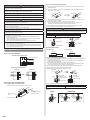
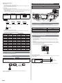
6. 1. Wiring method
6.1.1. Connection diagrams
Connection cable to outdoor unit
Wired remote controller cable
3-wire type
Red
Red
White
White
Black
2-wire type
or
Earth (ground) line
Power line
Control line
6.1.2. Connection cable preparation
Power supply cable or connection cable
Earth (ground)
wire
Keep the earth (ground) wire longer than the other wires.
Use a 4-core wire cable.
Power supply cable or
connection cable
40 mm or more
30 mm
How to connect wiring to the terminals.
(1) Use ring terminals with insulating sleeves as shown in the ¿gure below to connect to
the terminal block.
(2) Securely crimp the ring terminals to the wires using an appropriate tool so that the
wires do not come loose.
Strip 10 mm
Ring terminal
Sleeve
(3) Use the speci¿ed wires, connect them securely, and fasten them so that there is no
stress placed on the terminals.
(4) Use an appropriate screwdriver to tighten the terminal screws.
Do not use a screwdriver that is too small, otherwise, the screw heads may be
damaged and prevent the screws from being properly tightened.
(5) Do not tighten the terminal screws too much, otherwise, the screws may break.
(6) See the table below for the terminal screw tightening torques.
WARNING
Use ring terminals and tighten the terminal screws to the speci¿ed torques, otherwise,
it may cause abnormal overheating and possibly cause serious damage inside the unit.
Tightening torque [N·m (kgf·cm)]
M4 screw 1.2 to 1.8 (12 to 18)
Screw with
special washer
Ring terminal
Terminal blocks
Wire
Wire
Screw with
special
washer
Ring terminal
Remote controller cable
For 3-wire type
For 2 -wire type
30 mm 30 mm
How to connect wiring to the terminals.
(1) To connect the electrical terminal, follow the below diagram and connect after looping it
around the end of the cable.
(2) Use the speci¿ed cables, connect them securely, and fasten them so that there is no
stress placed on the terminals.
(3) Use an appropriate screwdriver to tighten the terminal screws.
Do not use a screwdriver that is too small, otherwise, the screw heads may be dam-
aged and prevent the screws from being properly tightened.
(4) Do not tighten the terminal screws too much, otherwise, the screws may break.
(5) See the table for the terminal screw tightening torques.
(6) Please do not ¿x 2 power supply cables with 1 screw.
Strip 30 mm
Loop
Cable
Cable
Screw with
special washer
Screw with
special washer
Cable end (Loop)
Cable end (Loop)
Terminal block
Do not apply branch wiring. It may cause electric shock or ¿re.
Tightening torque [N·m (kgf·cm)]
M3 screw 0.5 to 0.6 (5 to 6)
For ³Group control´, refer to the following ¿gure on how to connect to the indoor unit
terminal.
GOOD
PROHIBITED
Different diameter
Connect to 1 side

En-8
6.1.3. Wiring procedure
Connection cable
Remote controller cable
Control line
Power line
Connection
cable
Earth
(ground)
Outdoor unit
DIP switch
Control box
Print circuit board
(PCB)
3-wire type 2-wire type
Black
White
White
RedRed
Remote
controller
cable
Remote
controller
cable
Remote
controller
Remote
controller
Factory setting
Connecting the
Optional parts
Set to “3 WIRE”
“2 WIRE”
*Earth (Ground) the remote controller if it has a earth (ground) wire.
CAUTION
Tighten the indoor unit
connection wire and power supply indoor and outdoor unit, ter-
minal board connections ¿rmly with the terminal board screws. Faulty connection may
cause a
¿re.
Connect the indoor unit connection wire by matching the numbers of the outdoor and
indoor units terminal board numbers as shown in terminal label.
Be sure to refer to the connection diagram for the correct ¿eld wiring. Wrong wiring
causes malfunction of the unit.
6.1.4. Connection wiring
CAUTION
Be careful not to mistake the power supply cable and connection wires when installing.
Install so that the wires for the remote controller will not come in contact with other
connection wires.
(1) Remove the control box cover and wiring cover by loosening the screws.
Wiring connecting port
Wiring cover
Control box cover
(2) Thread each cable through the holes or indents of the cabinet and connect the wires.
(3) After wiring is complete, secure the cables with the cable clamps.
1
2
3
Cable clamp
Power supply cable or connection cable
Detail (a)
Y1 Y2 Y3 1 2Y1 Y2 Y3 1 2
Cable tie (small)
(Accessory)
Remote
controller
cable
Detail (b)

En-9
(4) Replace the Control box cover and Wiring cover. Securely tighten the screws.
Cure the wiring connecting port and remote controller connecting port with paste or heat
insulation so that insects or dust will not enter the unit
CAUTION
Do not bundle the remote controller cable, or wire the remote controller cable in paral-
lel, with the indoor unit connection wire (to the outdoor unit) and the power supply
cable. It may cause erroneous operation.
7. CASSETTE GRILLE INSTALLATION
Install according to the installation manual for Cassette grille.
Be sure to con¿rm there is no gap between the panel and main unit after installing the
Cassette grille.
8. REMOTE CONTROLLER INSTALLATION
Install according to the installation manual for Remote controller.
9. FUNCTION SETTING
9. 1. Turning on the power
CAUTION
Recheck the wiring. Incorrect wiring will cause trouble.
When initially starting up this unit, the following setting screen will be displayed. Settings
con¿gured at this stage can be changed afterwards.
9. 2. Setting method
See installation manual of remote controller.
9. 3. RC Sensor setting
The detection location of the room temperature can be selected from the following two
examples. Choose the detection location that is best for the installation location.
A. Indoor unit setting (factory setting)
The room temperature is detected by the indoor unit
temperature sensor.
B. Remote controller setting
The room temperature is detected by the remote
controller temperature sensor.
A
Indoor unit
B
Indoor unit
CAUTION
When selecting the “Remote controller setting”, if the detected temperature value
between the temperature sensor of the indoor unit and the temperature sensor of
the remote controller varies signi¿cantly, it is likely to return to the control status of
temperature sensor of the indoor unit temporarily.
As the temperature sensor of remote controller detects the temperature near the wall,
when there is a certain difference between the room temperature and the wall tempera-
ture, the sensor will not detect the room temperature correctly sometimes.
Especially when the outer side of the wall on which the sensor is positioned is exposed to
the open air, it is recommended to use the temperature sensor of the indoor unit to detect
the room temperature when the indoor and outdoor temperature difference is signi¿cant.
The temperature sensor of the remote controller is not only used when there is a problem
in the detection of the temperature sensor of the indoor unit.
9. 4. Function Details
Filter sign
Select appropriate intervals for displaying the ¿lter sign on the indoor unit according to the
estimated amount of dust in the air of the room.
If the indication is not required, select "No indication" (03).
(Ƈ... Factory setting)
Function
Number
Setting
Value
Setting Description
11
00 Standard (2500 hours)
01 Long interval (4400 hours)
02 Short interval (1250 hours)
03 No indication Ƈ
Ceiling height
Select the appropriate ceiling height according to the place of installation.
(Ƈ... Factory setting)
Function
number
Setting
value
Setting description
20
00
Standard (3.0 m : 18/25 type)
(3.2 m : 40/50 type)
Ƈ
01
High ceiling (3.5 m : 18/25 type)
(4.2 m : 40/50 type)
02 Low ceiling (2.7 m)
The ceiling height values are for the 4-way outlet.
Do not change this setting in the 3-way outlet mode.
Outlet directions
Select the appropriate number of outlet directions according to the installation conditions.
(Ƈ... Factory setting)
Function
number
Setting
value
Setting description
22
00 4-way Ƈ
01 3-way
Room temperature control for cooling
Depending on the installed environment, correction of the room temperature sensor may
be required.
Select the appropriate control setting according to the installed environment.
(Ƈ... Factory setting)
Function
Number
Setting
Value
Setting Description
30
00 Standard Ƈ
01 Lower control
02 Slightly higher control
03 Higher control
Room temperature control for heating
Depending on the installed environment, correction of the room temperature sensor may
be required.
Select the appropriate control setting according to the installed environment.
(Ƈ... Factory setting)
Function
Number
Setting
Value
Setting Description
31
00 Standard Ƈ
01 Lower control
02 Slightly lower control
03 Higher control

En-10
Auto restart
Enable or disable automatic restart after a power interruption.
(Ƈ... Factory setting)
Function
Number
Setting
Value
Setting Description
40
00 Enable Ƈ
01 Disable
* Auto restart is an emergency function such as for power outage etc. Do not attempt to
use this function in normal operation. Be sure to operate the unit by remote controller or
external device.
Room temperature sensor switching
(Only for wireless remote controller)
When using the Wired remote controller temperature sensor, change the setting to "Both"
(01).
(Ƈ... Factory setting)
Function
Number
Setting
Value
Setting Description
42
00 Indoor unit Ƈ
01 Both
00: Sensor on the indoor unit is active.
01: Sensors on both indoor unit and wired remote controller are active.
*
Remote controller sensor must be turned on by using the remote controller
Remote controller custom code
(Only for wireless remote controller)
The indoor unit custom code can be changed.
Select the appropriate custom code.
(Ƈ... Factory setting)
Function
Number
Setting
Value
Setting Description
44
00 A Ƈ
01 B
02 C
03 D
External input control
"Operation/Stop" mode or "Forced stop" mode can be selected.
(Ƈ... Factory setting)
Function
Number
Setting
Value
Setting Description
46
00 Operation/Stop mode 1 Ƈ
01 (Setting prohibited)
02 Forced stop mode
03 Operation/Stop mode 2
Room temperature sensor switching (Aux.)
To use the temperature sensor on the wired remote controller only, change the setting to
"Wired remote controller" (01). This function will only work if the function setting 42 is set
at "Both" (01)
(Ƈ... Factory setting)
Function
Number
Setting
Value
Setting Description
48
00 Both Ƈ
01 Wired remote controller
Switching functions for external output terminal
Functions of the external output terminal can be switched.
(Ƈ... Factory setting)
Function
Number
Setting
Value
Setting description
60
00 Operation status Ƈ
09 Error status
10 Indoor unit fan operation status
11 External heater
Setting record
w
Record any changes to the settings in the following table.
Function
number
Setting Setting Value
11 Filter sign
20 Ceiling height
22 Outlet directions
30
Room temperature control for indoor unit sensor
Cooling
31 Heating
40 Auto restart
42 Room temperature sensor switching
44 Remote controller custom code
46 External input control
48 Room temperature sensor switching (Aux.)
60
Switching function for external outlet terminal
After completing the function setting, be sure to turn off the power and turn it on again.
10. SPECIAL INSTALLATION METHODS
CAUTION
Be sure to turn off the electrical breaker before making settings.
Do not set the DIP switch or rotary switch of this unit except as speci¿ed in this
manual or the operating manual supplied with the air conditioner.
Setting the switches other than speci¿ed will cause an accident or trouble.
Do not touch the circuit board and circuit board parts directly with your hands. Other-
wise, injury or electric shock could result.
Use an insulated screwdriver to set the dip switches.
10. 1. Setting the address
RC AD
Y1 Y2 Y3 1 2
1
2
3
Y1 Y2 Y3 1 2
1234
ON

En-11
Remote controller address
(1) 3-wire type
DIP switch (RC AD SW)...Factory setting “0”
When connecting multiple indoor units to 1 standard wired remote controller, set the
address at RC AD SW in sequence from 0.
(2) 2-wire type
DIP switch (RC AD SW)...Factory setting “0”
Since the remote controller address settings are automatically con¿gured, you do not
need to con¿gure them.
If con¿guring manually, it is necessary to con¿gure both the indoor unit and the remote
controller. For details, please refer to the remote controller manual.
Setting Setting range Type of switch
Remote controller
address
0 to 15
Setting
example 0
1234
ON
RC AD
Example
If 4 indoor units are connected.
RC AD SW
0
RC AD SW
1
RC AD SW
2
RC AD SW
3
Indoor unit
Remote
controller
Indoor unit Indoor unit Indoor unit
Set the R.C. address (DIP switch setting)
Set the R.C. address of each indoor unit using the DIP switches on the indoor unit
circuit board. (See the following table and ¿gure.)
The DIP switches are normally set to make the R.C. address 00.
Indoor unit
R.C. address
DIP SWITCH No.
1234
1 00 OFF OFF OFF OFF
2 01 ON OFF OFF OFF
3 02 OFF ON OFF OFF
4 03 ON ON OFF OFF
5 04 OFF OFF ON OFF
6 05 ON OFF ON OFF
7 06 OFF ON ON OFF
807ONONONOFF
9 08 OFF OFF OFF ON
10 09 ON OFF OFF ON
11 10 OFF ON OFF ON
12 11 ON ON OFF ON
13 12 OFF OFF ON ON
14 13 ON OFF ON ON
15 14 OFF ON ON ON
16 15 ON ON ON ON
10. 2. Setting the DIP switch
See installation manual of remote controller.
10. 3. Group control
CAUTION
Group control is only possible between units with remote controllers of the same type.
To con¿rm the type of remote controller, see the back of the remote controller or
“2.3. Optional parts”.
With a single remote controller, up to 16 units can be simultaneously operated.
A
BCDE
I.U. I.U. I.U. I.U.
Master
A, B, C, D, E : Remote controller cable. (Refer to 3.3. Electrical requirement.)
A+B+C+D+E 500 m.
11. OPTION AND OTHER CONNECTABLE DEVICES
WARNING
Regulation of cable differs from each locality, refer in accordance with local rules.
Y1 Y2 Y3 1 2
1
2
3
Y1 Y2 Y3 1 2
Terminal
(External in)
CN48
(IR receiver)
CN65
(External in/out PCB)
CN47
(External out)
11. 1. Optional parts
This air conditioner can be connected with the following optional kits.
For details on how to install optional parts, refer to the installation manual included in each
item.
Option type Connector No.
UTY-LBT*C* (IR Receiver) CN48
UTY-XWZXZG (Connect wire) CN47*1
UTY-XCSX (External input and output PCB) CN65*2
*1:
For external output terminal setting, refer to Function No.60 in "8. FUNCTION SETTING".
*2: Various settings are available by using the optional External input and output PCB.
11. 2. External input and output
11.2.1. External input
Indoor unit functions such as Operation/Stop or Forced stop can be done by using
indoor unit terminals.
“Operation/Stop” mode or “Forced stop” mode can be selected with function setting of
indoor unit.
A twisted pair cable (22 AWG) should be used. Maximum length of cable is 150 m (492 ft.).
Use an external input and output cable with appropriate external dimension, depending
on the number of cables to be installed.
The wire connection should be separate from the power cable line.
Connected device
Terminal
Ɣ'U\FRQWDFWWHUPLQDO
When a power supply is unnecessary at the input device you want to connect, use the Dry
contact terminal.
*1
PCB
Terminal
(External in)
Connected device
*1: The switch can be used on the following condition: DC 12 V to 24 V, 1 mA to 15 mA.

En-12
Operation behavior
Ɣ,QSXWVLJQDOW\SH
Edge
ON
OFF
Ɣ:KHQIXQFWLRQVHWWLQJLV³2SHUDWLRQ6WRS´PRGH
Input signal Command
OFF ĺ ON Operation
ON ĺ OFF Stop
Ɣ:KHQIXQFWLRQVHWWLQJLV³)RUFHGVWRS´PRGH
Input signal Command
OFF ĺ ON Forced stop
ON ĺ OFF Normal
* When the forced stop is triggered, indoor unit stops and Operation/Stop operation by a
remote controller is restricted.
Ɣ:KHQIXQFWLRQVHWWLQJLV2SHUDWLRQ6WRSPRGH
Input signal Command
OFF ĺ ON Operation
ON ĺ OFF Stop (R.C. disabled)
11.2.2. External output
A twisted pair cable (22AWG) should be used. Maximum length of cable is 25 m (82 ft.).
Use an external input and output cable with appropriate external dimension, depending
on the number of cables to be installed.
Output voltage: Hi DC12V2V, Lo 0V.
Permissible current: 50mA
Output select
ƔWhen interlocking with external device
CN47
PCB
Connected
device
Relay (locally purchased)
or
Ɣ:KHQGLVSOD\LQJ2SHUDWLRQ6WRS
CN47
PCB
Connected device
Resistor
LED
Operation behavior
*If function setting "60" is set to "00"
Function setting
Status Output voltage
60
00
Stop 0V
Operation DC 12 V
09
Normal 0V
Error DC 12 V
10
Indoor unit fan stop 0V
Indoor unit fan operation DC 12 V
11
External heater OFF 0 V
External heater ON DC 12V
11.2.3. Connection methods
:LUHPRGL¿FDWLRQ
Remove insulation from wire attached to wire kit connector.
Remove insulation from locally purchased cable. Use crimp type insulated butt
connector to join ¿eld cable and wire kit wire.
Connect the wire with connecting wire with solder.
IMPORTANT: Be sure to insulate the connection between the wires.
Locally purchased
Option parts
External output wire
Solder and insulate the connected parts.
Connecting wires to the terminals.
Use ring terminals with insulating sleeves to connect to the terminal block.
Connection terminals and wiring arrangement
In following ¿gure, all the possible connections are done for description.
In actual installation, connections will differ according to each installation requirements.
1
2
3
PCB
Clamp
External
input/output PCB
communication wire
External
output wire
Y1 Y2 Y3 1 2Y1 Y2 Y3 1 2
External
input
wire
Clamp
12. CHECK LIST
Pay special attention to the check items below when installing the indoor unit(s). After
installation is complete, be sure to check the following check items again.
CHECK ITEMS If not performed correctly CHECK BOX
Has the indoor unit been installed
correctly?
Vibration, noise, indoor unit may
drop
Has there been a check for gas
leaks (refrigerant pipes)?
No cooling, No heating
Has heat insulation work been
completed?
Water leakage
Does water drain easily from the
indoor units?
Water leakage
Are the wires and pipes all con-
nected completely?
No operation, heat or burn dam-
age
Is the connection cable the speci¿ed
thickness?
No operation, heat or burn dam-
age
Are the inlets and outlets free of any
obstacles?
No cooling, No heating
After installation is completed, has
the proper operation and handling
been explained to the user?
13. TEST RUN
(1) Is operation of each button on the remote controller normal?
(2) Do not air Àow direction louvers operate normally?
(3) Is the drain normal?
(4) Is there any error noise and vibration during operation?
Do not operate the air conditioner test run for a long time.
See installation manual of remote controller
For how to carry out a test run, refer to 9. TEST RUN

En-13
14. CUSTOMER GUIDANCE
Explain the following to the customer in accordance with the operating manual:
(1) Starting and stopping method, operation switching, temperature adjustment, timer, air
Àow switching, and other remote controller unit operations.
(2) Cleaning and maintenance of the product, and other items such as air ¿lters and air
louvers if applicable.
(3) Give the operating and installation manuals to the customer.
(4) If the signal code is changed, explain to the customer how it changed (the system
returns to signal code A when the batteries in the remote controller unit are replaced).
*(4) is applicable to using wireless remote controller.
15. ERROR CODES
If you use a wired type remote controller, error codes will appear on the remote controller
display. For more information, refer to the installation manual of the remote controller. If you
use a wireless remote controller, the lamps on the IR receiver unit will output error codes
by way of blinking patterns. See the lamp blinking patterns and error codes in the table
below. An error display is displayed only during operation.
Error display
Wired
remote
controller
Error code
Description
OPERATION
lamp (green)
TIMER
lamp
(orange)
ECONOMY
lamp
(green)
y
(1)
y
(1)
Serial communication error
y
(1)
y
(2)
Wired remote controller
communication error
y
(1)
y
(5)
Check run un¿nished
y
(1)
y
(6)
Peripheral unit transmission PCB
connection error
y
(1)
y
(8)
External communication error
y
(2)
y
(1)
Unit number or Refrigerant circuit
address setting error
[Simultaneous Multi]
y
(2)
y
(2)
Indoor unit capacity error
y
(2)
y
(3)
Combination error
y
(2)
y
(4)
Connection unit number
error (indoor secondary unit)
[Simultaneous Multi]
Connection unit number error
(indoor unit or branch unit)
[Flexible Multi]
y
(2)
y
(6)
Indoor unit address setting error
y
(2)
y
(7)
Primary unit, secondary unit setup
error [Simultaneous Multi]
y
(2)
y
(9)
Connection unit number error in
wired remote controller system
y
(3)
y
(1)
Power supply interruption error
y
(3)
y
(2)
Indoor unit PCB model
information error
y
(3)
y
(5)
Manual auto switch error
y
(3)
y
(10)
Indoor unit communication circuit
(wired remote controller) error
y
(4)
y
(1)
Room temp. sensor error
y
(4)
y
(2)
Indoor unit Heat Ex. Middle temp.
sensor error
y
(4)
y
(4)
Human sensor error
y
(5)
y
(1)
Indoor unit fan motor error
y
(5)
y
(3)
Drain pump error
y
(5)
y
(7)
Damper error
y
(5)
y
(15)
Indoor unit error
Error display
Wired
remote
controller
Error code
Description
OPERATION
lamp (green)
TIMER
lamp
(orange)
ECONOMY
lamp
(green)
y
(6)
y
(1)
Outdoor unit reverse/missing
phase and wiring error
y
(6)
y
(2)
Outdoor unit main PCB
model information error or
communication error
y
(6)
y
(3)
Inverter error
y
(6)
y
(4)
Active ¿lter error, PFC circuit error
y
(6)
y
(5)
Trip terminal L error
y
(6)
y
(8)
Outdoor unit rush current limiting
resister temp. rise error
y
(6)
y
(10)
Display PCB microcomputers
communication error
y
(7)
y
(1)
Discharge temp. sensor error
y
(7)
y
(2)
Compressor temp. sensor error
y
(7)
y
(3)
Outdoor unit Heat Ex. liquid temp.
sensor error
y
(7)
y
(4)
Outdoor temp. sensor error
y
(7)
y
(5)
Suction Gas temp. sensor error
y
(7)
y
(6)
2-way valve temp. sensor error
3-way valve temp. sensor error
y
(7)
y
(7)
Heat sink temp. sensor error
y
(8)
y
(2)
Sub-cool Heat Ex. gas inlet
temp. sensor error
Sub-cool Heat Ex. gas outlet
temp. sensor error
y
(8)
y
(3)
Liquid pipe temp. sensor error
y
(8)
y
(4)
Current sensor error
y
(8)
y
(6)
Discharge pressure sensor error
Suction pressure sensor error
High pressure switch error
y
(9)
y
(4)
Trip detection
y
(9)
y
(5)
Compressor rotor position
detection error (permanent stop)
y
(9)
y
(7)
Outdoor unit fan motor 1 error
y
(9)
y
(8)
Outdoor unit fan motor 2 error
y
(9)
y
(9)
4-way valve error
y
(9)
y
(10)
Coil (expansion valve) error
y
(10)
y
(1)
Discharge temp. error
y
(10)
y
(3)
Compressor temp. error
y
(10)
y
(4)
High pressure error
y
(10)
y
(5)
Low pressure error
y
(13)
y
(2)
Branch boxes error
[Flexible Multi]
Display mode
y
: 0.5s ON / 0.5s OFF
: 0.1s ON / 0.1s OFF
( ) : Number of Àashing
-
 1
1
-
 2
2
-
 3
3
-
 4
4
-
 5
5
-
 6
6
-
 7
7
-
 8
8
-
 9
9
-
 10
10
-
 11
11
-
 12
12
-
 13
13
-
 14
14


Fujitsu RCA18URTA-S Guide d'installation
- Catégorie
- Climatiseurs split-system
- Taper
- Guide d'installation
dans d''autres langues
Documents connexes
-
Fujitsu ASAG07LMCA Guide d'installation
-
Fujitsu ASU9RLF1 Guide d'installation
-
Fujitsu UOSH30AXJ Guide d'installation
-
Fujitsu AOYA72LALT Guide d'installation
-
Fujitsu ASGA30FUTC-B Guide d'installation
-
-
Fujitsu AOU48RLXFZ1 Guide d'installation
-
-
-
Autres documents
-
Haier 4U30HS1ERA Guide d'installation
-
Friedrich FPHFC36A3B Mode d'emploi
-
Mitsubishi MSZ-HJ35VA Le manuel du propriétaire
-
-
Haier AC60FS1ERA Manuel utilisateur
-
-
Mitsubishi Electric city multi PLFY-P-VCM-E2 Guide d'installation
-
-
Mitsubishi Electric Mr. SLim SEZ-KD15NA Guide d'installation
-
Toshiba MMU-AP0071YH Manuel utilisateur