Eaton Powerware 9125 Guide d'installation
- Catégorie
- Alimentations sans interruption (UPS)
- Taper
- Guide d'installation

Powerware 9125 (9910-P10, P11, P15, P16) UPS
Installation Guide for IBM Applications
Guide d’Installation Onduleur pour Applications IBM
USV Installationsanleitung für IBM-Anwendungen
Guida all’Installazione dell’UPS per le Applicazioni IBM
Guía de Instalación del SIE para Aplicaciones de IBM
®
®

Powerware and X-Slot are registered trademarks of Eaton Electrical Inc.
Powerware et X-Slot sont des marques déposées de Eaton Electrical Inc.
Powerware und X-Slot sind ein eingetragene Warenzeichen der Eaton Electrical Inc.
Powerware e X-Slot sono marchi di fabbrica depositato della Eaton Electrical Inc.
Powerware y X-Slot son marcas comerical registradas de Eaton Electrical Inc.
ECopyright 2006 Eaton Corporation, Raleigh, NC, USA. All rights reserved. No part of this document may be
reproduced in any way without the express written approval of Eaton Corporation.
ECopyright 2006 Eaton Corporation, Raleigh, NC, USA. Tous droits réservés. Aucune partie de ce document ne
peut être reproduite d’une quelconque manière sans l’accord écrit explicite de Eaton Corporation.
ECopyright 2006 Eaton Corporation, Raleigh, NC, USA. Alle Rechte vorbehalten. Kein Teil dieser Druckschrift darf
ohne ausdrückliche schriftliche Genehmigung von Eaton Corporation auf irgendeine Weise vervielfältigt werden.
ECopyright 2006 Eaton Corporation, Raleigh, NC, USA. Tutti i diritti riservati. Nessuna parte del presente
documento può essere riprodotta in alcun modo senza l’esplicita autorizzazione scritta di Eaton Corporation.
ECopyright 2006 Eaton Corporation, Raleigh, NC, USA. Todos los derechos reservados. Queda prohibida la
reproducción total o parcial de este documento sin el expreso consentimiento por escrito de Eaton Corporation.

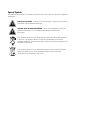
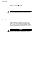
Special Symbols
The following are examples of symbols used on the UPS or accessories to alert you to important
information:
RISK OF ELECTRIC SHOCK - Indicates that a risk of electric shock is present and the
associated warning should be observed.
CAUTION: REFER TO OPERATOR’S MANUAL - Refer to your operator’s manual for
additional information, such as important operating and maintenance
instructions.
This symbol indicates that you should not discard the UPS or the UPS batteries
in the trash. This product contains sealed, lead -acid batteries and must be
disposed of properly. For more information, contact your local recycling/reuse or
hazardous waste center.
This symbol indicates that you should not discard waste electrical or electronic
equipment (WEEE) in the trash. For proper disposal, contact your local
recycling/reuse or hazardous waste center.

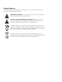
Symboles Spéciaux
Voici des exemples de symboles utilisés sur l’onduleur ou ses accessoires pour vous alerter
concernant des informations importantes :
RISQUE DE CHOC ELECTRIQUE - Indique la présence d’un risque de choc électrique
et l’avertissement associé devant être observé.
ATTENTION : SE REPORTER AU MANUEL DE L’OPERATEUR - Reportez-vous à votre
manuel de l’opérateur pour des informations supplémentaires telles que les
instructions importantes de fonctionnement et de maintenance.
Ce symbole indique que vous ne devez pas jeter l’onduleur ou les batteries de
l’onduleur à la poubelle. Ce produit contient des batteries au plomb étanches et
doit être mis au rebut en conséquence. Pour plus d’informations, contactez votre
centre local de recyclage ou de dépôt de déchets dangereux.
Ce symbole indique que vous ne devez pas jeter de déchets électriques ou
électroniques (WEEE) à la poubelle. Pour une mise au rebut adéquate, contactez
votre centre local de recyclage ou de dépôt de déchets dangereux.

Besondere Symbole
Im Folgenden werden die Symbole aufgeführt, die an USV-Geräten bzw. deren Zubehör
verwendet werden, und die Sie auf wichtige Informationen aufmerksam machen:
STROMSCHLAGGEFAHR - Gibt an, dass eine Stromschlaggefahr besteht und die
entsprechende Warnung beachtet werden muss.
VORSICHT! SIEHE BEDIENUNGSANLEITUNG - Weitere Angaben, wie etwa wichtige
Bedienungs- und Wartungsanweisungen, sind der Bedienungsanleitung zu
entnehmen.
Dieses Symbol bedeutet, dass die USV oder die Akkus der USV nicht in den Müll
gegeben werden dürfen. Dieses Produkt enthält versiegelte Bleibatterien, die
vorschriftsmäßig zu entsorgen sind. Nähere Informationen erhalten Sie bei Ihrem
örtlichen Recyclinghof/Sondermüllentsorger.
Dieses Symbol gibt an, dass Abfälle von Elektro- und Elektronikgeräten (engl.
Abk.: WEEE) nicht über den normalen Müll entsorgt werden dürfen. Nähere
Informationen erhalten Sie bei Ihrem örtlichen
Recyclinghof/Sondermüllentsorger.

Simboli Speciali
La sezione che segue riporta esempi dei simboli utilizzati sull’UPS o sugli accessori per mettere in
evidenza informazioni importanti:
RISCHIO DI SCOSSE ELETTRICHE - Indica il rischio di scosse elettriche e la necessità
di osservare le avvertenze descritte.
ATTENZIONE: CONSULTARE IL MANUALE DELL’UTENTE - Indica che è necessario
consultare il manuale dell’utente per ulteriori informazioni, ad esempio per
istruzioni importanti sull’uso e la manutenzione dell’unità.
Questo simbolo indica che non è possibile smaltire l’UPS o le batterie come
normali rifiuti. Il presente prodotto contiene batterie al piombo-acido sigillate e
deve essere smaltito correttamente. Per ulteriori informazioni contattare il locale
centro di riciclaggio/recupero e smaltimento rifiuti pericolosi.
Questo simbolo indica che non è possibile smaltire dispositivi elettrici o
elettronici (WEEE) come normali rifiuti. Per un corretto smaltimento contattare il
locale centro di riciclaggio/recupero e smaltimento rifiuti pericolosi.

Símbolos Especiales
Los siguientes son ejemplos de los símbolos que se utilizan en el SIE o en los accesorios para
alertarlo sobre información importante:
RIESGO DE DESCARGA ELÉCTRICA - Indica un riesgo de descarga eléctrica y debe
tomar las advertencias relacionadas.
PRECAUCIÓN: CONSULTE EL MANUAL DEL OPERADOR - Consulte el manual del
operador para obtener información adicional como importantes instrucciones
sobre funcionamiento y mantenimiento.
Este símbolo indica que no debe desechar el SIE o las baterías del SIE en la
basura. Este producto contiene baterías selladas de ácido de plomo y se deben
desechar de manera apropiada. Para obtener más información, comuníquese con
el centro local de reciclado o reutilización de desechos peligrosos.
Este símbolo indica que no debe desechar equipo electrónico o eléctrico (WEEE
por sus siglas en inglés) en la basura. Para la eliminación correcta, comuníquese
con el centro local de reciclado o reutilización de desechos peligrosos.

This page intentionally left blank.

EATON Powerware
®
9125 (9910-P10, P11, P15, P16) UPS Installation Guide for IBM
®
Applications S 164201633 Rev A
i
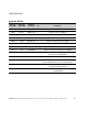
Table of Contents
Installation 1.........................................................
Parts List 1..........................................................................
UPS Internal Battery Connection 2..........................................................
Setup and Installation 3.................................................................
Rack-Mount Setup 3.................................................................
Tower Setup 4.....................................................................
Installing the UPS 7.................................................................
UPS Monitoring 9......................................................................
UPS Rear Panels 10.....................................................................
Service and Support 11..................................................................
Table des Matières
Installation 13.........................................................
Liste des Pièces 13.....................................................................
Connexion à la Batterie Interne de l’Onduleur 14................................................
Configuration et Installation 15.............................................................
Configuration en baie 15...............................................................
Configuration en tour 17...............................................................
Installation de l’onduleur 20............................................................
Surveillance de l’onduleur 22..............................................................
Panneaux arrières de l’onduleur 23..........................................................
Service après-vente et assistance technique 24.................................................

TABLE OF CONTENTS
EATON Powerware
®
9125 (9910-P10, P11, P15, P16) UPS Installation Guide for IBM
®
Applications S 164201633 Rev A
ii
Inhaltsverzeichnis
Einbau 25............................................................
Teileliste 25..........................................................................
Interner USV-Batterieanschluss 26..........................................................
Montage und Installation 27...............................................................
Montage im Gestell 27................................................................
Montage im Tower 29.................................................................
Installieren der USV 31................................................................
USV-Überwachung 34...................................................................
Rückwände der USV 35..................................................................
Kundendienst und Unterstützung 36.........................................................
Sommario
Installazione 37.......................................................
Elenco Parti 37........................................................................
Collegamento Batteria Interna UPS 38........................................................
Approntamento e Installazione 39...........................................................
Allestimento montaggio su rastrelliera 39...................................................
Approntamento tower 40..............................................................
Installazione della UPS 43..............................................................
Monitoraggio UPS 45....................................................................
Pannelli posteriori UPS 46................................................................
Assistenza e supporto 47.................................................................

TABLE OF CONTENTS
EATON Powerware
®
9125 (9910-P10, P11, P15, P16) UPS Installation Guide for IBM
®
Applications S 164201633 Rev A
iii
Contenido
Instalación 49.........................................................
Lista de Partes 49......................................................................
Conexión de la Batería Interna del SIE 50......................................................
Configuración e Instalación 51.............................................................
Configuración de montaje de bastidor 51...................................................
Configuración de la torre 52............................................................
Instalación del SIE 56.................................................................
Control del SIE 58......................................................................
Paneles posteriores del SIE 59.............................................................
Servicio y soporte 60....................................................................

TABLE OF CONTENTS
EATON Powerware
®
9125 (9910-P10, P11, P15, P16) UPS Installation Guide for IBM
®
Applications S 164201633 Rev A
iv
This page intentionally left blank.

EATON Powerware
®
9125 (9910-P10, P11, P15, P16) UPS Installation Guide for IBM
®
Applications S 164201633 Rev A
1
Installation
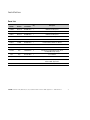
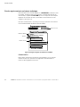
Parts List
IBM Part
Number
IBM Model
Number
Eaton
Part Number
Qty. Description
39J4806 9910-P10 05146002-3991 1 1000 VA Low Voltage UPS
39J4807 9910-P11 05146011-3991 1 1000 VA High Voltage UPS
39J4811 9910-P15 05146005-3991 1 1500 VA Low Voltage UPS
39J4812 9910-P16 05146006-3991 1 1500 VA High Voltage UPS
39J4808 FC 6604 05146502-3991 1 Extended Battery Module for 1000 VA
39J4813 FC 6605 05146074-3991 1 Extended Battery Module for 1500 VA
N/A N/A 152601975-001 1 UPS to AS/400 Communication Cable
N/A N/A 124102044-001 1 UPS to RS/6000 Communication Cable
21H1576 N/A 152601942-001 6 IEC 320-C13 to C14 Equipment Power Cords
for 1000/1500 VA High Voltage
N/A N/A 05141562-0091 1 4-Post Rail Kit
N/A N/A 103004870 1 Power Management Software Suite with Communication Cable
N/A N/A 164201633 1 Powerware 9125 (9910-P10, P11, P15, P16) UPS Installation
Guide for IBM Applications
N/A N/A 164201514 1 Powerware 9125 Two-in-One UPS (700–2000 VA) User’s Guide

INSTALLATION
EATON Powerware
®
9125 (9910-P10, P11, P15, P16) UPS Installation Guide for IBM
®
Applications S 164201633 Rev A
2
UPS Internal Battery Connection
NOTE Check the battery recharge date on the shipping carton label. If the date has expired
and the batteries were never recharged, do not use the UPS. Contact your service
representative.
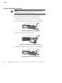
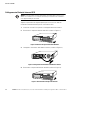
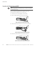
To ensure proper battery operation before installing the UPS:
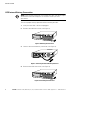
1. Verify that the UPS is off and unplugged.
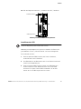
2. Remove the UPS front cover (see Figure 1).
Figure 1. Removing the Front Cover
3. Connect the internal battery connector (see Figure 2).
Figure 2. Connecting the Internal Battery Connector
4. Reinstall the UPS front cover (see Figure 3).
Figure 3. Reinstalling the Front Cover

INSTALLATION
EATON Powerware
®
9125 (9910-P10, P11, P15, P16) UPS Installation Guide for IBM
®
Applications S 164201633 Rev A
3
Setup and Installation
The Powerware 9125 UPS is designed for flexible configurations and can
be installed in a rack or as a standalone cabinet.
If you are installing the UPS in a rack, continue to the following section
“Rack-Mount Setup;” otherwise, continue to “Tower Setup” on
page 4.
Rack-Mount Setup
The UPS can be installed in 19- or 23-inch r acks and needs only 2U of
valuable rack space.
NOTE Fixed mounting r ails are required for each UPS and EBM cabinet. If fixed rails are
not already installed in your rack, contact your local IBM representative to order a rail kit(s). If
you are installing the UPS in a non-IBM rack, contact your Powerware representative.
To install the UPS in a rack:
1. Place the UPS on a flat, stable surface with the front of the UPS
facing toward you.
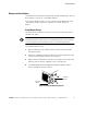
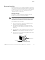
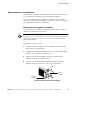
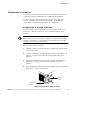
2. Attach the supplied mounting handles to the mounting brackets and
secure with the supplied screws (see Figure 4).
3. Align the mounting brackets with the screw holes on the side of the
UPS and secure with the supplied screws (see Figure 4).
4. If installing optional Extended Battery Modules (EBMs), repeat
Steps 1 through 3 for each cabinet.
Mounting
Handle
Mounting
Bracket
Figure 4. Installing the Mounting Brackets

INSTALLATION
EATON Powerware
®
9125 (9910-P10, P11, P15, P16) UPS Installation Guide for IBM
®
Applications S 164201633 Rev A
4
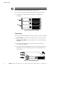
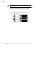
NOTE The EBMs must be installed below the UPS as shown in Figure 5.
5. Slide the UPS and any optional EBMs into the rack.
6. Secure the units to the rack according to the rail kit instructions.
7. Continue to “Installing the UPS” on page 7 to complete the
installation.
UPS
Optional
EBMs
Figure 5. Rack-Mount UPS with EBMs
Tower Setup
The setup varies depending on the number of cabinets you are installing:
1. For one cabinet, the pedestals must be installed. Continue to Step 2.
For two or more cabinets, the joining brackets must be installed. Skip
to Step 6.
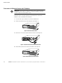
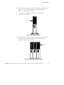
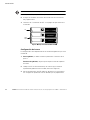
2. Place the UPS horizontally so that the left end of the cabinet is
accessible (see Figure 6).
3. Slide and align the UPS pedestals with the screw holes on the end
of the UPS. Secure the pedestals with the screws provided in the
accessory kit.
Figure 6. Installing the UPS Pedestals

INSTALLATION
EATON Powerware
®
9125 (9910-P10, P11, P15, P16) UPS Installation Guide for IBM
®
Applications S 164201633 Rev A
5
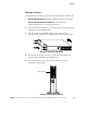
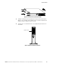
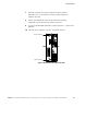
4. Carefully position the cabinet upright with the air vents at the top
(see Figure 7).
5. Continue to the following section, “Installing the UPS,” on page 7
to complete the installation.
Air Vents
Figure 7. UPS with Pedestals
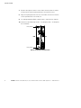
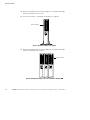
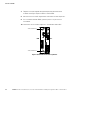
6. Carefully position the cabinets upright with the air vents at the top
(see Figure 8).
Air Vents
Figure 8. Tower UPS with EBMs

INSTALLATION
EATON Powerware
®
9125 (9910-P10, P11, P15, P16) UPS Installation Guide for IBM
®
Applications S 164201633 Rev A
6
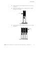
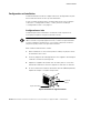
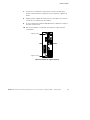
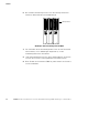
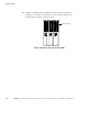
7. Remove the adjacent corner screws from the rear panels as shown
in Figure 9 to install the joining brackets. Discard the screws.
8. Align each joining bracket with the screw holes and secure with the
screws provided in the accessory kit.
9. If installing additional EBMs, repeat Steps 7 and 8 for each cabinet.
10. Continue to the following section, “Installing the UPS,” to complete
the installation.
Joining Bracket
Joining Bracket
EBM UPS
Figure 9. Installing the Joining Brackets

INSTALLATION
EATON Powerware
®
9125 (9910-P10, P11, P15, P16) UPS Installation Guide for IBM
®
Applications S 164201633 Rev A
7
Installing the UPS
NOTE Do not make unauthorized changes to the UPS; otherwise, damage may occur to
your equipment and void your warranty.
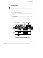
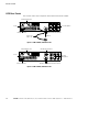
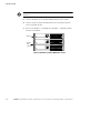
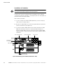
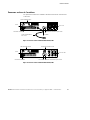
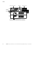
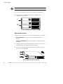
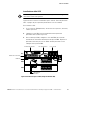
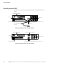
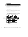
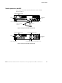
Figure 10 shows a typical installation only. See “UPS Rear Panels” on
page 10 for the rear panel of each model.
To install the UPS and optional EBMs:
1. If installing an optional EBM, continue to Step 2; otherwise, skip to
Step 4.
2. Plug the EBM cable of the first EBM into the UPS battery connector
(see Figure 10).
3. If additional EBMs are to be installed, plug the EBM cable of the
second cabinet into the battery connector on the first EBM. Repeat
for each additional EBM. Up to four EBMs may be connected to the
UPS.
UPS Battery
Connector
Power Cord
EBM Cable
Output Receptacles
Relay Interface Card
UPS
EBM
EBM
EBM Battery
Connectors
Figure 10. Typical Installation (120V UPS Model Shown)

INSTALLATION
EATON Powerware
®
9125 (9910-P10, P11, P15, P16) UPS Installation Guide for IBM
®
Applications S 164201633 Rev A
8
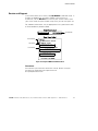
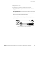
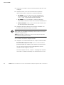
4. Verify that the AS/400 and other equipment to be protected by the
UPS is powered off.
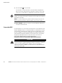
5. Connect one of the supplied communication cables to the UPS
communication port according to your computer system:
S For the AS/400. Use the supplied AS/400 communication cable.
The “AS/400” end of the cable connects to the port marked
“J14” or “UPS”on the AS/400 rear panel.
S For the RS/6000. If you are installing power management software,
use the supplied RS/6000 communication cable.
S For PCs and workstations. Use the communication cable supplied
with the power management software CD.
6. Plug your equipment into the appropriate UPS output receptacles
using the equipment power cords supplied with the UPS.
NOTE If you are using the Load Segment feature, see the Powerware 9125 Two-in-One
UPS (700–2000 VA) User’s Guide for more information on controlling and assigning the load
segments.
NOTE DO NOT p rotect laser printers with the UPS because of the exceptionally high power
requirements of the heating elements.
7. Turn on the equipment that is connected to the UPS.
8. Plug the power cord from the UPS into a power outlet.
For 230V models (including P11 and P16). Use the AS/400 or RS/6000
power cord to connect the UPS to the power outlet.
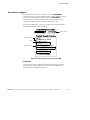
All front panel indicators flash briefly and the UPS conducts a
self-test.
When the self-test is complete, the
μ
indicator flashes, indicating
the UPS is in Standby mode with the equipment offline.
La page est en cours de chargement...
La page est en cours de chargement...
La page est en cours de chargement...
La page est en cours de chargement...
La page est en cours de chargement...
La page est en cours de chargement...
La page est en cours de chargement...
La page est en cours de chargement...
La page est en cours de chargement...
La page est en cours de chargement...
La page est en cours de chargement...
La page est en cours de chargement...
La page est en cours de chargement...
La page est en cours de chargement...
La page est en cours de chargement...
La page est en cours de chargement...
La page est en cours de chargement...
La page est en cours de chargement...
La page est en cours de chargement...
La page est en cours de chargement...
La page est en cours de chargement...
La page est en cours de chargement...
La page est en cours de chargement...
La page est en cours de chargement...
La page est en cours de chargement...
La page est en cours de chargement...
La page est en cours de chargement...
La page est en cours de chargement...
La page est en cours de chargement...
La page est en cours de chargement...
La page est en cours de chargement...
La page est en cours de chargement...
La page est en cours de chargement...
La page est en cours de chargement...
La page est en cours de chargement...
La page est en cours de chargement...
La page est en cours de chargement...
La page est en cours de chargement...
La page est en cours de chargement...
La page est en cours de chargement...
La page est en cours de chargement...
La page est en cours de chargement...
La page est en cours de chargement...
La page est en cours de chargement...
La page est en cours de chargement...
La page est en cours de chargement...
La page est en cours de chargement...
La page est en cours de chargement...
La page est en cours de chargement...
La page est en cours de chargement...
La page est en cours de chargement...
La page est en cours de chargement...
La page est en cours de chargement...
La page est en cours de chargement...
-
 1
1
-
 2
2
-
 3
3
-
 4
4
-
 5
5
-
 6
6
-
 7
7
-
 8
8
-
 9
9
-
 10
10
-
 11
11
-
 12
12
-
 13
13
-
 14
14
-
 15
15
-
 16
16
-
 17
17
-
 18
18
-
 19
19
-
 20
20
-
 21
21
-
 22
22
-
 23
23
-
 24
24
-
 25
25
-
 26
26
-
 27
27
-
 28
28
-
 29
29
-
 30
30
-
 31
31
-
 32
32
-
 33
33
-
 34
34
-
 35
35
-
 36
36
-
 37
37
-
 38
38
-
 39
39
-
 40
40
-
 41
41
-
 42
42
-
 43
43
-
 44
44
-
 45
45
-
 46
46
-
 47
47
-
 48
48
-
 49
49
-
 50
50
-
 51
51
-
 52
52
-
 53
53
-
 54
54
-
 55
55
-
 56
56
-
 57
57
-
 58
58
-
 59
59
-
 60
60
-
 61
61
-
 62
62
-
 63
63
-
 64
64
-
 65
65
-
 66
66
-
 67
67
-
 68
68
-
 69
69
-
 70
70
-
 71
71
-
 72
72
-
 73
73
-
 74
74


Eaton Powerware 9125 Guide d'installation
- Catégorie
- Alimentations sans interruption (UPS)
- Taper
- Guide d'installation
dans d''autres langues
Documents connexes
-
Eaton Powerware 9910-P30 Guide d'installation
-
Eaton Powerware 5125 Guide d'installation
-
-
-
-
-
-
Autres documents
-
Powerware 9125 Guide d'installation
-
-
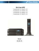 PowerWalker VFI 1500RT Manuel utilisateur
-
-
-
-
-
Bradley 2904-280000 Guide d'installation
