La page est en cours de chargement...

Reset
Ethernet
5 V
4 3 2 1
LED
HF
Reset
Ethernet
5 V
4 3 2 1
LED
HF
12.8000.2004
12.8000.2004
ROTRONIC AG, CH-8303 Bassersdorf
Tel. +41 44 838 11 44, www.rotronic.com
ROTRONIC Messgeräte GmbH, D-76275 Ettlingen
Tel. +49 7243 383 250, www.rotronic.de
ROTRONIC SARL, 56, F - 77183 Croissy Beaubourg
Tél. +33 1 60 95 07 10, www.rotronic.fr
ROTRONIC Italia srl, I- 20157 Milano
Tel. +39 2 39 00 71 90, www.rotronic.it
ROTRONIC Instruments (UK) Ltd, West Sussex RH10 9EE
Phone +44 1293 571000, www.rotronic.co.uk
ROTRONIC Instrument Corp, NY 11788, USA
Phone +1 631 427-3898, www.rotronic-usa.com
ROTRONIC Canada Inc.,Canada L8W 3P7
Phone + 1 905 754 51 64, www.rotronic.ca
ROTRONIC Instruments Pte. Ltd., Singapore 159836
Phone +65 6376 2107, www.rotronic.sg
ROTRONIC Shanghai Rep. Offi ce, Shanghai 200233, China
Phone +86 40 08162018, www.rotronic.cn
Herzlichen Glückwunsch zum Kauf Ihres neuen LAN-Interfaces. Sie haben damit ein dem neuesten
Stand der Technik entsprechendes Gerät erworben. Bitte lesen Sie diese Kurzanleitung genau
durch, bevor Sie das Gerät installieren.
Best.-Nr. Gerätetyp
LAN-INTERFACE LAN-Interface 433,92 MHz
LAN-INTERFACE-US LAN-Interface 915 MHz (USA)
Allgemeine Beschreibung
Das LAN-Interface ermöglicht unter Verwendung einer Ethernet-Infrastruktur die Kommunikation
mit drahtlosen Geräten über eine grössere Entfernung hinweg. Die Platzierung mehrer Interfaces
an unterschiedlichen Standorten ermöglicht den Zugriff auf räumlich verteilte Endgeräte von
einem zentralen Ort aus. Diese Kurzanleitung behandelt die Standortwahl, Aufstellung und den
Anschluss des Interfaces.
Hinweise zur Nutzung
Zur Nutzung des LAN-Interfaces wird eine konfi gurierte Ethernet-Infrastruktur mit 100 MBit/s
Übertragungsrate benötigt. Das Gerät ermöglicht im Zusammenspiel mit der HW4-Software die
Kommunikation mit geeigneten Funkgeräten. Zur Konfi guration der Ethernet-Parameter des LAN-
Interface wird ein PC mit HW4 oder einem gängigen Webbrowser (z.B. Firefox, InternetExplorer)
benötigt, welcher in die gleiche Ethernet-Infrastruktur eingebunden ist. Das LAN-Interface und
das mitgelieferte Steckernetzteil sind ausschliesslich für die Verwendung im Innenraumbereich
ausgelegt.
Geräteansicht und Standardkonfi guration
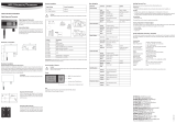
Anschlüsse und LEDs:
5V Netzteilanschluss
Ethernet RJ45-Netzwerkanschluss
Reset Drucktaster zum Zurücksetzen der Netzwerkkonfi guration in den
Auslieferungszustand.
HF Antennenanschluss
LED1 Spannungsversorgung
LED2 Funkdaten werden gesendet (blitzend)
LED3 Empfangene Funkdaten werden verarbeitet (blitzend)
LED4 Status, blinkend in folgenden variablen Intervallen (s.u.)
Das LAN-Interface ist bei Auslieferung mit folgenden Netzwerkeinstellungen konfi guriert:
IP 192.168.1.120
Netmask 255.255.255.0
Gateway 192.168.1.1
DNS 192.168.1.1
Netzwerkname rotroniclan
DHCP an
KURZBEDIENUNGSANLEITUNG
Standortwahl
Für eine optimale Sende- und Empfangsreichweite ist der Standort in trockenen Innenräumen
nach folgenden Kriterien zu wählen:
• Waagerecht, frei zugänglich (nicht durch Gegenstände verstellt)
• Keine metallischen Gegenstände (Wasserleitungen, Stahlschränke, o.ä.)
• Idealerweise besteht eine «Sichtverbindung» zwischen Antenne und anzusprechendem Gerät
• Sonneneinstrahlung, Feuchtigkeit und Temperaturwechsel vermeiden
Anschluss
Überwurfmutter des Antennensteckers auf den goldfarbenen HF-Anschluss handfest aufschrauben.
Das Gerät mit einem geeigneten Patchkabel über die Ethernet-Buchse mit der Netzwerkinfrastruktur
verbinden. Den Hohlstecker des Netzteils in die 5V-Buchse des Gerätes einstecken.
Hinweis: Bei Änderungen am Antennen- oder Netzwerkanschluss ist das Gerät vorher vom
Stromnetz zu trennen!
Reset: Drucktaster zum Zurücksetzen der Netzwerkkonfi guration in den Auslieferungszustand.
Erste Inbetriebnahme:
Nachdem das Gerät zum ersten Mal mit dem Stromnetz verbunden wurde, leuchtet LED1 auf
und das LAN-Interface durchläuft die folgende Startphase, deren Status durch LED4 gezeigt wird:
25ms: Netzwerkkonfi guration wird per DHCP abgefragt.
100ms: DHCP-Anfrage Fehlgeschlagen, keine benutzerdefi nierten Einstellungen vorhanden.
Die Netzwerkschnittstelle wurde automatisch mit den Werten bei Auslieferungs-
zustand konfi guriert
1s: Netzwerkkonfi guration wurde erfolgreich vom DHCP-Server bezogen.
2s: Benutzerdefi nierte Netzwerkkonfi guration (DHCP-Nutzung deaktiviert).
Die Netzwerkkonfi guration sollte nun über das Webinterface oder die HW4-Software (siehe auch
Dokumentation der HW4) angepasst und individualisiert werden.
Verwendete Ports
Beim Betrieb des LAN-Interfaces in einem Firmennetzwerk müssen folgende Ports auf der Firewall
offen sein:
– TCP 6767 (Kommunikation mit HW4 und LAN-Interface)
– TCP 3384 (Suche des LAN-Interface)
– UDP 67, 68, 69, 9 (Firmware update LAN-Interface)
Technische Daten:
Gehäuse Aluminium, Schutzart IP20
Antennenanschluss SMA-Stecker (50 Ω)
Einsatzbereich -20 bis +85 °C, max. 90 %rF
Netzwerkanschluss Fast Ethernet (10/100MBit) via RJ45-Stecker
Stromversorgung 5 VDC / <200 mA (5mm-Hohlstecker)
LAN-INTERFACE
Congratulations on your purchase of the new state-of-the-art LAN-Interfae. Please read these short
instructions carefully before installing the device.
Order Code Device type
LAN-INTERFACE LAN Interface 433,92 MHz Version
LAN-INTERFACE-US LAN Interface 915 MHz USA Version
General description
The LAN interface communicates with wireless devices over a greater distance by using an Ether-
net infrastructure. The placement of multiple interfaces in different locations provides access to
spatially distributed devices from a central location. This quick reference guide is limited to the
description of the main features and the installation of the device.
Handling
The LAN interface requires a confi gured Ethernet infrastructure with a transfer rate of 100MBit.
The device enables the interaction with the HW4 software to communicate with appropriate
radio equipment. To confi gure the Ethernet parameters of the LAN interface, a PC with HW4 or a
standard Web browser (eg Firefox, Internet Explorer) which is integrated into the same Ethernet
infrastructure is required. The LAN interface and the included AC adapter designed exclusively
for use in interior areas.
Device View and Standard Confi guration
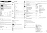
Connectors and LEDs
5V Power supply connector
Ethernet RJ45- Network Connection
Reset Push button to reset the network confi guration to factory default.
HF Antenna connection
LED1 Power supply
LED2 Radio data is sent (blinking)
LED3 Received radio data is processed (blinking)
LED4 Status, blinking in the following variable intervals (see below)
The LAN interface is confi gured upon delivery with the following network settings
IP 192.168.1.120
Netmask 255.255.255.0
Gateway 192.168.1.1
DNS 192.168.1.1
Network name rotroniclan
DHCP on
SHORT INSTRUCTION MANUAL
Choice of location:
For optimal transmission and reception range the interior site of placement has to meet the fol-
lowing criteria:
• Horizontal, freely accessible (not blocked by objects).
• Do not place close to metallic objects (water pipes, steel cabinets, etc.).
• Ideally, there is a “visual connection” between the antenna and the device.
• Avoid direct sunlight, moisture and temperature changes.
Connection
Screw the antenna clockwise to the gold colored RF connector. Mount he antenna only by turning the
nut. Connect the device via the Ethernet port to the network infrastructure by using an appropriate
patch cable. Connect the AC adapter to the mains and the 5V jack of the device.
Note: Prior to changes of the antenna or network connection, the device has to be separated
from the mains!
Reset: Push button to reset the network confi guration to its factory defaults.
Initial Setup
After the device is connected for the fi rst time the mains LED1 starts fl ashing. The LAN-Interface
now follows the below start-up-sequence, shown by LED4:
25ms: Network confi guration is queried via DHCP.
100ms: DHCP request failed, no custom settings available. The network interface is
automatically confi gured with factory settings
1s: Network confi guration was successfully obtained from the DHCP server.
2s: Custom network confi guration (DHCP disabled).
Now the network confi guration should be customized by using HW4 software
Ports used
During operation of the LAN interfaces in a corporate network, the following ports must be open
on the fi rewall:
– TCP 6767 (communication with HW4 and LAN-INTERFACE)
– TCP 3384 (search of the LAN-INTERFACE)
– UDP 67, 68, 69, 9 (fi rmware update LAN-INTERFACE)
Technical Specifi cations:
Housing Alu, protection class IP20
Antenna connector SMA connector (50 Ω)
Range of use -20 to +85 °C, max. 90 %RH
Network Connection Fast Ethernet (10/100MBit) via RJ45 connector
Power Supply 5 VDC / <200 mA (5mm jack connector)
LAN-INTERFACE

Reset
Ethernet
5 V
4 3 2 1
LED
HF
Reset
Ethernet
5 V
4 3 2 1
LED
HF
12.8000.2004
12.8000.2004
ROTRONIC AG, CH-8303 Bassersdorf
Tel. +41 44 838 11 44, www.rotronic.com
ROTRONIC Messgeräte GmbH, D-76275 Ettlingen
Tel. +49 7243 383 250, www.rotronic.de
ROTRONIC SARL, 56, F - 77183 Croissy Beaubourg
Tél. +33 1 60 95 07 10, www.rotronic.fr
ROTRONIC Italia srl, I- 20157 Milano
Tel. +39 2 39 00 71 90, www.rotronic.it
ROTRONIC Instruments (UK) Ltd, West Sussex RH10 9EE
Phone +44 1293 571000, www.rotronic.co.uk
ROTRONIC Instrument Corp, NY 11788, USA
Phone +1 631 427-3898, www.rotronic-usa.com
ROTRONIC Canada Inc.,Canada L8W 3P7
Phone + 1 905 754 51 64, www.rotronic.ca
ROTRONIC Instruments Pte. Ltd., Singapore 159836
Phone +65 6376 2107, www.rotronic.sg
ROTRONIC Shanghai Rep. Offi ce, Shanghai 200233, China
Phone +86 40 08162018, www.rotronic.cn
Tous nos remerciements pour l’achat d’une des nouvelles interfaces LAN. Vous avez fait l’acquisition
d’un appareil qui intègre les derniers développements de la technique. Veuillez lire attentivement
ce manuel abrégé avant d’installer l’appareil.
N
o
de commande Type d’appareil
LAN-INTERFACE Interface LAN version 433,92 MHz
LAN-INTERFACE-US Interface LAN version USA 915 MHz
Description générale
En combinaison avec une infrastructure Ethernet, l’interface LAN permet la communication avec
des appareils sans fi ls situés à une grande distance. Le positionnement de plusieurs interfaces
à différents endroits autorise l’accès depuis un poste central, à des appareils terminaux dissé-
minés dans des locaux. Ce manuel abrégé traite du choix du positionnement, du montage et du
raccordement de l’interface.
Indications pour l’utilisation
Une infrastructure Ethernet capable d’un taux de transfert de 100 MBit est nécessaire pour
l’utilisation de l’interface LAN. En liaison avec le logiciel HW4, l’appareil permet de communiquer
avec des appareils radio adéquats. Un PC relié au même réseau et équipé du logiciel HW4 ou d’un
navigateur Internet commun (p.ex. Firefox, Internet Explorer) est nécessaire pour la confi guration
des paramètres de l’interface LAN. L’interface LAN et l’adaptateur secteur fourni sont conçus
exclusivement pour une utilisation en intérieur.
Vue de l’appareil et confi guration standard
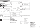
Raccordements et LEDs:
5V Raccordement à l’alimentation
Ethernet Raccordement au réseau RJ45
Reset Touche-pression pour la réinitialisation de la confi guration du réseau
sur les paramètres de sortie d’usine
HF Raccordement à une antenne
LED1 Tension d’alimentation
LED2 Les données radio sont envoyées (éclairs)
LED3 Les données radios reçues sont traitées (éclairs)
LED4 État, clignotant à intervalle variable (voir ci-contre)
L’interface LAN est confi gurée à sa livraison avec les paramètres suivants:
IP 192.168.1.120
Masque Net 255.255.255.0
Gateway 192.168.1.1
DNS 192.168.1.1
Nom du réseau rotroniclan
DHCP an
MODE D'EMPLOI ABRÉGÉ
Choix du lieu d’installation
Pour une portée optimale d’émission et une bonne réception, il est indispensable de choisir un
endroit sec, en intérieur et disposant des critères suivants:
• Plan horizontal, libre d’accès (éviter l’encombrement par des objets)
• Éviter la proximité d’objets métalliques (conduites d’eau, armoires métalliques, etc.)
• Le positionnement idéal devrait assurer une « liaison visuelle directe » entre l’antenne et les
appareils à relier. Éviter le rayonnement solaire, l’humidité et les variations de température.
Raccordement
Visser l’antenne tige dans le sens des aiguilles d’une montre sur le raccordement HF doré. Le
montage de l’antenne doit uniquement être effectué avec la collerette de fi xation. Relier l’appareil
à l’infrastructure Ethernet avec un câble de brassage adapté à la prise femelle Ethernet. Relier la
fi che mâle de l’adaptateur secteur à la prise femelle 5V de l’appareil.
Remarque: déconnecter l’appareil du secteur avant d’effectuer une quelconque modifi cation sur
l’antenne ou le raccordement au secteur!
Reset: Touche-pression pour la réinitialisation de la confi guration du réseau sur les paramètres
de sortie d’usine.
Première mise en service:
La LED1 s’illumine après la première connexion de l’appareil au réseau électrique et l’interface
LAN effectue les phases de démarrage suivantes dont le statut est indiqué par la LED4:
25ms: la confi guration du réseau est en cours de consultation par DHCP.
100ms: la consultation par DHCP a échoué, aucun réglage d’utilisateur n’est défi ni.
L’interface du réseau a été confi gurée automatiquement avec les valeurs de sortie
d’usine.
1s: La confi guration du réseau a été transférée avec succès du serveur DHCP.
2s: Confi guration du réseau défi nie par l’utilisateur (usage de DHCP désactivé).
La confi guration du réseau devrait être adaptée et individualisée par l’interface Web ou le logiciel
HW4 (voir également la documentation du logiciel HW4).
Ports utilisés
Pendant le fonctionnement des interfaces LAN dans un réseau d'entreprise, les ports suivants
doivent être ouverts sur le pare-feu:
– TCP 6767 (communication avec HW4 ou interface LAN)
– TCP 3384 (recherche de l'interface LAN)
– UDP 67, 68, 69, 9 (Mise à jour Firmware Interface LAN)
Caractéristiques techniques:
Boîtier Aluminium, type de protection IP20
Raccordement de l’antenne Connecteur SMA (50 Ω)
Gamme d’utilisation -20 à +85 °C, humidité maximale de l’air 90%
Raccordement réseau Fast Ethernet (10/100MBit) par connecteur RJ45
Alimentation électrique 5 VCC / <200 mA (Fiche jack)
INTERFACE LAN
MANUALE D'ISTRUZIONI BREVE
LAN-INTERFACE
Ci congratuliamo per l'acquisto della vostra nuova interfaccia LAN. Avete acquistato uno strumento
al passo con le tecnologie più moderne. Prima di installare lo strumento, si prega di leggere la
presente guida rapida.
Codice Tipo strumento
LAN-INTERFACE Interfaccia LAN versione a 433.92 MHz
LAN-INTERFACE-US Interfaccia LAN versione USA a 915 MHz
Descrizione generale
L'interfaccia LAN consente la comunicazione con apparecchi wireless anche a grande distanza,
ricorrendo ad un'infrastruttura Ethernet. Il posizionamento di diverse interfacce in punti di
installazione differenti permette l'accesso da un punto centrale a terminali spazialmente distri-
buiti. La presente guida rapida tratta della scelta del punto di installazione, del montaggio e del
collegamento dell'interfaccia.
Avvertenze per l'uso
Per utilizzare un'interfaccia LAN serve un'infrastruttura Ethernet confi gurata con una velocità di
trasmissione a 100 MBit. Associato al software HW4, l'apparecchio consente la comunicazione
con apparecchi wireless idonei. Per la confi gurazione dei parametri Ethernet dell'interfaccia LAN
è necessario un PC con l'HW4 o un web-browser di uso corrente (per esempio Firefox, Internet
Explorer), integrato nella stessa infrastruttura Ethernet. L'interfaccia LAN e l'alimentatore a spina
fornito in dotazione sono progettati esclusivamente per l'uso indoor.
Immagine degli apparecchi e confi gurazione standard
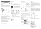
Collegamenti e LED:
5V Collegamento alimentatore
Ethernet Collegamento di rete RJ45
Reset Pulsante per il ripristino della confi gurazione di rete allo
stato di default
HF Collegamento dell'antenna
LED1 Alimentazione della tensione
LED2 Trasmissione dei dati wireless (lampeggiante)
LED3 Dati wireless ricevuti in elaborazione (lampeggiante)
LED4 Stato, lampeggiante con i seguenti intervalli variabili (si veda di seguito)
L'interfaccia LAN presenta una confi gurazione di default con le seguenti impostazioni di rete:
IP 192.168.1.120
Netmask 255.255.255.0
Gateway 192.168.1.1
DNS 192.168.1.1
Nome della rete rotroniclan
DHCP ON
Scelta del punto di installazione
Onde ottenere portate di trasmissione e ricezione ottimali, si dovrà scegliere il punto di installazione
in locali asciutti e sulla base dei criteri seguenti:
• Orizzontale, liberamente accessibile (non ostruito da oggetti)
• Nessun oggetto metallico (condotte idriche, armadietti di acciaio, o similari)
• L'ideale sarebbe il "collegamento visivo" fra l'antenna e l'apparecchio pertinente
• Evitare esposizione ai raggi solari, umidità e sbalzi di temperatura
Connessione
Avvitare in senso orario l'antenna ad asta sul collegamento HF color oro. Il montaggio dell'antenna si
effettua esclusivamente con il dado. Collegare l'apparecchio all'infrastruttura di rete tramite un cavo
patch idoneo attraverso il connettore femmina Ethernet. Collegare la spina jack dell'alimentatore
al connettore femmina da 5 V dell'apparecchio.
Avvertenza: in caso di modifi che al collegamento dell'antenna o di rete, per prima cosa staccare
l'apparecchio dall'alimentazione di corrente!
Reset: pulsante per il ripristino della confi gurazione di rete allo stato di default.
Prima messa in servizio:
Successivamente al primo collegamento tra l'apparecchio e l'alimentazione di rete, il LED1 si
illuminerà e l'interfaccia LAN attraverserà la fase di avviamento seguente, il cui stato sarà evi-
denziato dal LED4:
25ms: La confi gurazione di rete viene richiesta attraverso il protocollo DHCP.
100ms: Richiesta DHCP fallita, indisponibilità di impostazioni "user defi ned".
L'interfaccia di rete è stata automaticamente confi gurata con i valori di
default.
1s: La confi gurazione di rete è stata ricevuta con successo dal server DHCP.
2s: Confi gurazione di rete "user defi ned" (disattivato l'utilizzo del DHCP).
Ora la confi gurazione di rete dovrebbe essere adeguata e personalizzata mediante l'interfaccia
web o il software HW4 - si veda anche la documentazione dell'HW4.
Porte usate
Durante il funzionamento delle interfacce LAN in una rete aziendale, le seguenti porte devono
essere aperte sul fi rewall:
– TCP 6767 (la comunicazione con HW4 e interfaccia LAN)
– TCP 3384 (ricerca dell'interfaccia LAN)
– UDP 67, 68, 69, 9 (aggiornamento fi rmware interfaccia LAN)
Dati tecnici:
Alloggiamento Alluminio, classe di protezione IP20
Collegamento antenna Spina SMA (50 Ω)
Range operativo Da -20 a +85 °C, max. 90%ur
Collegamento di rete Ethernet veloce (10/100 MBit)
mediante connettore maschio RJ45
Alimentazione di corrente 5 VDC / <200 mA (Spina jack)
1/2