Faber CAPR36SS600 Guide d'installation
- Catégorie
- Hottes
- Taper
- Guide d'installation
Ce manuel convient également à

Installation Instructions
Use and Care Information
Instructions d'installation
Utilisez et d'entretien
Instrucciones de instalación
Información de uso y cuidado
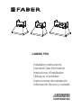
CAMINO PRO
CAPR36SS600
CAPR36SS1200
CAPR48SS1200

2
READ AND SAVE THESE INSTRUCTIONS BEFORE YOU START
INSTALLING THIS RANGEHOOD
WARNING: - TO REDUCE THE RISK OF A RANGE TOP GREASE FIRE:
a) Never leave surface units unattended at high settings. Boilovers cause smoking and
greasy spillovers that may ignite. Heat oils slowly on low or medium setting.
A KV@XRSTQMGNNC.-VGDMBNNJHMF@SGHFGGD@SNQVGDMl@LADHMFENNCHD"QDODR
Suzette, Cherries Jubilee, Peppercorn Beef Flambé).
c) Clean ventilating fans frequently. Grease should not be allowed to accumulate on fan
NQkKSDQ
d) Use proper pan size. Always use cookware appropriate for the size of the surface element.
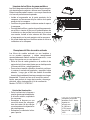
WARNING: - TO REDUCE THE RISK OF INJURY TO PERSONS IN THE EVENT OF A
RANGE TOP GREASE FIRE, OBSERVE THE FOLLOWING*:
@2,.3'$1%+ ,$2VHSG@BKNRDkSSHMFKHCBNNJHDRGDDSNQLDS@KSQ@XSGDMSTQMNEESGDATQMDQ
!$" 1$%4+3./1$5$-3!41-2(ESGDl@LDRCNMNSFNNTSHLLDCH@SDKX$5 "4 3$
AND CALL THE FIRE DEPARTMENT.
b) NEVER PICK UP A FLAMING PAN - You may be burned.
c) DO NOT USE WATER, including wet dishcloths or towels - a violent steam explosion will
result.
d) Use an extinguisher ONLY if:
1. You know you have a Class ABC extinguisher, and you already know how to operate it.
3GDkQDHRRL@KK@MCBNMS@HMDCHMSGD@QD@VGDQDHSRS@QSDC
3GDkQDCDO@QSLDMSHRADHMFB@KKDC
8NTB@MkFGSSGDkQDVHSGXNTQA@BJSN@MDWHS
* Based on "Kitchen Firesafety Tips" published by NFPA
WARNING - TO REDUCE THE RISK OF FIRE OR ELECTRIC SHOCK, do not use this
fan with any solid-state speed control device.
WARNING - TO REDUCE THE RISK OF FIRE, ELECTRICAL SHOCK, OR INJURY TO
PERSONS, OBSERVE THE FOLLOWING:
1. Use this unit only in the manner intended by the manufacturer. If you have any
questions, contact the manufacturer.
2. Before servicing or cleaning unit, switch power off at service panel and lock the
service disconnecting means to prevent power from being switched on acciden-
tally. When the service disconnecting means cannot be locked, securely fasten a
prominent warning device, such as a tag, to the service panel.
CAUTION: For General Ventilating Use Only. Do Not Use To Exhaust Hazardous or
Explosive Materials and Vapors.
WARNING - TO REDUCE THE RISK OF FIRE, ELECTRICAL SHOCK, OR INJURY TO
PERSONS, OBSERVE THE FOLLOWING:
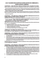
1. (MRS@KK@SHNM6NQJ MC$KDBSQHB@K6HQHMF,TRS!D#NMD!X0T@KHkDC/DQRNMR(M BBNQ-
dance With All Applicable Codes And Standards, Including Fire-Rated Construction.
2. 2TEkBHDMS@HQHRMDDCDCENQOQNODQBNLATRSHNM@MCDWG@TRSHMFNEF@RDRSGQNTFG
SGDlTDBGHLMDXNEETDKATQMHMFDPTHOLDMSSNOQDUDMSA@BJCQ@ESHMF%NKKNVSGD
heating equipment manufacturer's guideline and safety standards such as those
OTAKHRGDCAXSGD-@SHNM@K%HQD/QNSDBSHNM RRNBH@SHNM-%/ @MCSGD LDQHB@M
2NBHDSXENQ'D@SHMF1DEQHFDQ@SHNM@MC HQ"NMCHSHNMHMF$MFHMDDQR 2'1 $@MC
the local code authorities.

3
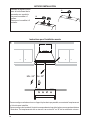
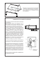
ALL WALL AND FLOOR OPENINGS WHERE THE RANGEHOOD IS INSTALLED MUST
BE SEALED.
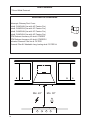
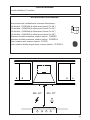
This rangehood requires at least 24" of clearance between the bottom of the rangehood
and the cooking surface or countertop. This hood has been approved by UL at this distance
from the cooktop.
This minimum clearance may be higher depending on local building codes. For gas cooktops
and combination ranges, a minimum of 30" is recommended and may be required.
Overhead cabinets on both sides of this unit must be a minimum of 18" above the cooking surface
or countertop. Consult the cooktop or range installation instructions given by the manufacturer
before making any cutouts.
MOBILE HOME INSTALLATION The installation of this rangehood must conform to the
Manufactured Home Construction and Safety Standards, Title 24 CFR, Part 3280 (formerly
Federal Standard for Mobile Home Construction and Safety, Title 24, HUD, Part 280). See
Electrical Requirements.
• Venting system MUST terminate outside the home.
• DO NOT terminate the ductwork in an attic or other enclosed space.
• DO NOT use 4" laundry-type wall caps.
• Flexible-type ductwork is not recommended.
• DO NOTNARSQTBSSGDkNVNEBNLATRSHNM@MCUDMSHK@SHNM@HQ
q%@HKTQDSNENKKNVUDMSHMFQDPTHQDLDMSRL@XQDRTKSHM@jQD
WARNING
!
VENTING REQUIREMENTS
Determine which venting method is best for your application. Ductwork can extend either through the
wall or the roof.
3GDKDMFSGNESGDCTBSVNQJ@MCSGDMTLADQNEDKANVRRGNTKCADJDOSSN@LHMHLTLSNOQNUHCDDEjBHDMS
performance. The size of the ductwork should be uniform. Do not install two elbows together. Use
CTBSS@ODSNRD@K@KKINHMSRHMSGDCTBSVNQJRXRSDL4RDB@TKJHMFSNRD@KDWSDQHNQV@KKNQkNNQNODMHMF
around the cap.
Flexible ductwork is not recommended. Flexible ductwork creates back pressure and air turbulence
that greatly reduces performance.
,@JDRTQDSGDQDHROQNODQBKD@Q@MBDVHSGHMSGDV@KKNQkNNQENQDWG@TRSCTBSADENQDL@JHMFBTSNTSR
Do not cut a joist or stud unless absolutely necessary. If a joist or stud must be cut, then a supporting
frame must be constructed.
WARNING - To Reduce The Risk Of Fire, Use Only Metal Ductwork.
" 43(.-3NQDCTBDQHRJNEkQD@MCSNOQNODQKXDWG@TRS@HQADRTQDSNCTBS@HQNTSRHCDm#N
not vent exhaust air into spaces within walls or ceilings or into attics, crawl spaces, or garages.
3. When cutting or drilling into wall or ceiling, do not damage electrical wiring and
other hidden utilities.
4. Ducted fans must always be vented to the outdoors.

4
• Electrical ground is required on this rangehood.
• If cold water pipe is interrupted by plastic, nonmetallic gaskets or other materials, DO
NOT use for grounding.
• DO NOT ground to a gas pipe.
• DO NOT have a fuse in the neutral or grounding circuit. A fuse in the neutral or
grounding circuit could result in electrical shock.
q"GDBJVHSG@PT@KHjDCDKDBSQHBH@MHEXNT@QDHMCNTAS@RSNVGDSGDQSGDQ@MFDGNNCHR
properly grounded.
q%@HKTQDSNENKKNVDKDBSQHB@KQDPTHQDLDMSRL@XQDRTKSHM@jQD
WARNING
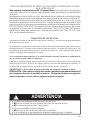
2S@SDNE"@KHENQMH@/QNONRHSHNM6@QMHMF42NMKX
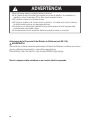
WARNING
This product contains chemicals known to the State of California to cause cancer and birth
defects or other reproductive harm.
For more information go to www.P65Warnings.ca.gov
Note: The hood needs to be installed on a separate electrical circuit.

5
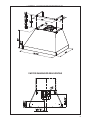
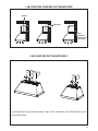
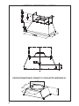
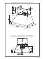
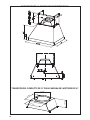
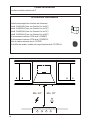
1 MOTOR - RANGEHOOD DIMENSIONS 36"
1 MOTOR RANGEHOOD REAR VENTING

6
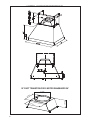
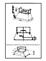
2 MOTOR - RANGEHOOD DIMENSIONS 36"
9 13/16”
11 7/16”
11 1/16”
4 15/16”
10" DUCT TRANSITION FOR 2 MOTOR RANGEHOOD 36"

7
2 MOTOR - RANGEHOOD DIMENSIONS 48"
9 13/16”
11 7/16”
11 1/16”
4 15/16”
10" DUCT TRANSITION FOR 2 MOTOR RANGEHOOD 48"

8
7
6
9e
8
8
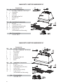
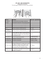
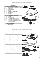
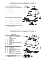
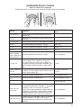
MAIN PARTS 1 MOTOR RANGEHOOD 36"
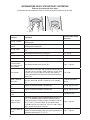
Components
Ref. Qty. Product Components
*UHDVH¿OWHUV
Ref. Qty. Installation Components
*UHDVH¿OWHUVVFUHZV[
H 0RWRU¿[VFUHZV[
IRU5HFLUFXODWLRQ9HQW*ULOOPRXQWLQJ
Qty. Documentation
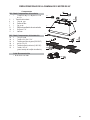
MAIN PARTS 2 MOTOR RANGEHOOD 36"
Components
Ref. Qty. Product Components
*UHDVH¿OWHUV
Ref. Qty. Installation Components
*UHDVH¿OWHUVVFUHZV[
H 0RWRU¿[VFUHZV[
IRU5HFLUFXODWLRQ9HQW*ULOOPRXQWLQJ
Qty. Documentation
1
12a
12b
7
6
9e
12a
12b
10
10
1
2
12c
12c
12d
12e
12e
9
12f
9
12f
11
11

9
8
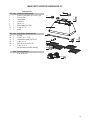
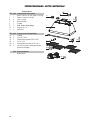
MAIN PARTS 2 MOTOR RANGEHOOD 48"
Components
Ref. Qty. Product Components
*UHDVH¿OWHUV
Ref. Qty. Installation Components
*UHDVH¿OWHUVVFUHZV[
H 0RWRU¿[VFUHZV[
IRU5HFLUFXODWLRQ9HQW*ULOOPRXQWLQJ
Qty. Documentation
7
6
9e
12a
12b
10
1
2
12c
12d
12e
9
12f
11

10
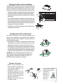
AVAILABLE ACCESSORIES
PARTS NEEDED
6" Round Metal Ductwork
Telescopic Chimney Duct Cover:
- sku#: CHIM3448 (Use with 48" Camino Pro)
- sku#: CHIM2224 (Use with 36" Camino Pro)
- sku#: CHIM2248 (Use with 36" Camino Pro)
- sku#: CHIM3424 (Use with 48" Camino Pro)
CFM Reducer Accessory Kit sku#: CFMRED
CFM Reducer Accessory Kit sku#: CFMRED-2
Activated Charcoal Filter sku #: FILTER1
Charcoal Filter Kit Washable Long Lasting sku#: FILTER1LL
Min. 24" Min. 30"

11
6"
Rear
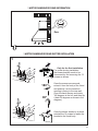
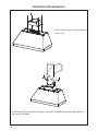
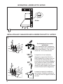
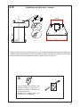
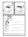
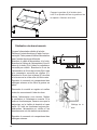
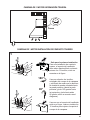
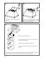
1 MOTOR RANGEHOOD REAR INFORMATION
2QO\IRUWKH¿UVWLQVWDOODWLRQ
For a rear ducting installation
the blower bracket needs to be
XQVHFXUHGE\¿UVWUHPRYLQJWKH
screws as shown.
Once the screws are removed,
extract it from the body of the Hood
and position it so the transition
opening is facing to the rear wall
(from the back remove and rotate
GHJUHHVWRWKHOHIWDQGWKHQÀLS
it back 90 degrees as shown in the
diagram).
Once the blower bracket is in place
reinstall the 12 screws to fasten the
bracket to the Hood body.
1
1 MOTOR RANGEHOOD REAR DUCTED INSTALLATION
180°
90°

12
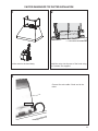
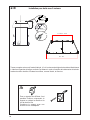
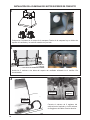
Install the motor into the upper of the hood using
the 2 screws 12e supplied.
Put the motor in the hood body.
2 3
4
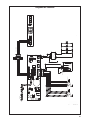
9 hole end
Connect the wire cable 9 hole end to the
motor.

13
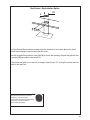
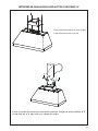
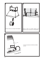
1 MOTOR RANGEHOOD TOP DUCTED INSTALLATION
1 2
Install the motor into the rear of the hood using
the 2 screws 12e supplied.
Put the motor in the hood body.
3
9 hole end
Connect the wire cable 9 hole end to the
motor.

14
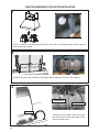
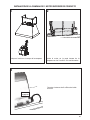
Install the 2 motors into the sides of the blower bracket using the 4 screws 12e supplied.
Put the 2 motors in the hood body. Inside the hood there is a blower bracket divider and the
motors will be one a side.
1
2
FIGURE 16
3
9 hole end
Connect the wire cable 9 hole end to the
left motor and the other wire cable 9 hole
end to the right motor.
9 hole end
9 hole end
2 MOTOR RANGEHOOD TOP DUCTED INSTALLATION

15
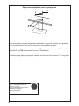
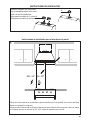
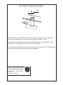
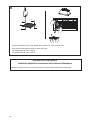
Install Damper that is included with the
Hood before connecting to the ductwork.
One for 1 motor model.
Two for 2 motor model.
H
I
H
I
H
I
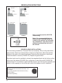
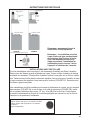
INSTALLATION INSTRUCTIONS
==
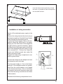
Installation Instruction for Mounting on the Wall
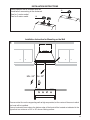
Draw a vertical line on the supporting wall as high as practical, at the center of the area in which
the hood will be installed.
Draw a horizontal line at where the bottom edge of the hood will be located as indicated in the
¿JXUHWKDWLVDPLQLPXPRIRUDERYHFRRNLQJVXUIDFH
1
Min. 24" Min. 30"

16
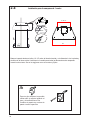
Ø 1/2”
x2
x2
24”
L
16 1/2”
30”
L = 19 11/16”
36”
2.a
Mark the wall where indicated, 16 1/2" above the horizontal line and at L distance on the left and right
of vertical line. The distance L changes for all dimension of Hood.
,QVHUWWKHWZRZDOOSOXJVDLQWKHKROHVDVVKRZQDQG¿[WKHP
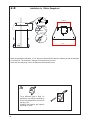
Installation for 1 Motor Rangehood
For a different type of Wall, it's
possible to use only the bracket by
remove the plug and the screw from
the plug 12a.
&RPELQH WKH EUDFNHW ZLWK VSHFL¿F
wall plug or screw.

17
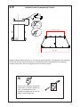
Ø 1/2”
x2
x2
24”
L
16 1/2”
30”
L = 19 11/16” - 31 1/8”
36” - 48”
2.b
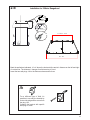
Installation for 2 Motor Rangehood
Mark the wall where indicated, 16 1/2" above the horizontal line and at L distance on the left and right
of vertical line. The distance L changes for all dimension of Hood.
,QVHUWWKHWZRZDOOSOXJVDLQWKHKROHVDVVKRZQDQG¿[WKHP
For a different type of Wall, it's
possible to use only the bracket by
remove the plug and the screw from
the plug 12a.
&RPELQH WKH EUDFNHW ZLWK VSHFL¿F
wall plug or screw.

18
Ø 5/16”
x4
x4
x4
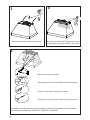
Hook the hood body onto the wall plugs 12a. Use a level to insure that Fixing Bracket is level
by adjusting the screws as shown in the picture.
Mark the wall where indicated.
Drill directly into ø 5/16" holes at all the center points marked.
Insert the purchased wall plugs in the holes.
Using thhe remaining screws to anchor the hood in holes.
If installation uses the telescopic chimney extension, refer to the installation manual included in
the Chimney Kit (CHIM3448 - CHIM2224 - CHIM2248 - CHIM3424)
11b
3
4
5

19
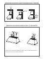
1 AND 2 MOTORS DUCTING METHODS 6"
1 AND 2 MOTORS STANDARD DUCTING METHODS
Vertical
Horizontal
Rear
5@KHCENQ
motor range-
hood only)

20
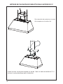
2 MOTORS DUCTING METHODS 10"
Fix the Duct transition in the hood body with
4 screws 12d.
La page est en cours de chargement...
La page est en cours de chargement...
La page est en cours de chargement...
La page est en cours de chargement...
La page est en cours de chargement...
La page est en cours de chargement...
La page est en cours de chargement...
La page est en cours de chargement...
La page est en cours de chargement...
La page est en cours de chargement...
La page est en cours de chargement...
La page est en cours de chargement...
La page est en cours de chargement...
La page est en cours de chargement...
La page est en cours de chargement...
La page est en cours de chargement...
La page est en cours de chargement...
La page est en cours de chargement...
La page est en cours de chargement...
La page est en cours de chargement...
La page est en cours de chargement...
La page est en cours de chargement...
La page est en cours de chargement...
La page est en cours de chargement...
La page est en cours de chargement...
La page est en cours de chargement...
La page est en cours de chargement...
La page est en cours de chargement...
La page est en cours de chargement...
La page est en cours de chargement...
La page est en cours de chargement...
La page est en cours de chargement...
La page est en cours de chargement...
La page est en cours de chargement...
La page est en cours de chargement...
La page est en cours de chargement...
La page est en cours de chargement...
La page est en cours de chargement...
La page est en cours de chargement...
La page est en cours de chargement...
La page est en cours de chargement...
La page est en cours de chargement...
La page est en cours de chargement...
La page est en cours de chargement...
La page est en cours de chargement...
La page est en cours de chargement...
La page est en cours de chargement...
La page est en cours de chargement...
La page est en cours de chargement...
La page est en cours de chargement...
La page est en cours de chargement...
La page est en cours de chargement...
La page est en cours de chargement...
La page est en cours de chargement...
La page est en cours de chargement...
La page est en cours de chargement...
La page est en cours de chargement...
La page est en cours de chargement...
La page est en cours de chargement...
La page est en cours de chargement...
La page est en cours de chargement...
La page est en cours de chargement...
La page est en cours de chargement...
La page est en cours de chargement...
-
 1
1
-
 2
2
-
 3
3
-
 4
4
-
 5
5
-
 6
6
-
 7
7
-
 8
8
-
 9
9
-
 10
10
-
 11
11
-
 12
12
-
 13
13
-
 14
14
-
 15
15
-
 16
16
-
 17
17
-
 18
18
-
 19
19
-
 20
20
-
 21
21
-
 22
22
-
 23
23
-
 24
24
-
 25
25
-
 26
26
-
 27
27
-
 28
28
-
 29
29
-
 30
30
-
 31
31
-
 32
32
-
 33
33
-
 34
34
-
 35
35
-
 36
36
-
 37
37
-
 38
38
-
 39
39
-
 40
40
-
 41
41
-
 42
42
-
 43
43
-
 44
44
-
 45
45
-
 46
46
-
 47
47
-
 48
48
-
 49
49
-
 50
50
-
 51
51
-
 52
52
-
 53
53
-
 54
54
-
 55
55
-
 56
56
-
 57
57
-
 58
58
-
 59
59
-
 60
60
-
 61
61
-
 62
62
-
 63
63
-
 64
64
-
 65
65
-
 66
66
-
 67
67
-
 68
68
-
 69
69
-
 70
70
-
 71
71
-
 72
72
-
 73
73
-
 74
74
-
 75
75
-
 76
76
-
 77
77
-
 78
78
-
 79
79
-
 80
80
-
 81
81
-
 82
82
-
 83
83
-
 84
84


Faber CAPR36SS600 Guide d'installation
- Catégorie
- Hottes
- Taper
- Guide d'installation
- Ce manuel convient également à
dans d''autres langues
- English: Faber CAPR36SS600 Installation guide
- español: Faber CAPR36SS600 Guía de instalación
Documents connexes
-
Faber CAPR36SS600 Guide d'installation
-
-
-
-
-
-
Faber TRAT30SS600B Guide d'installation
-
-
Faber CLAS30SS300B Guide d'installation
-

