Johnson Controls FX-WRZRMT10K-0 Guide d'installation
- Taper
- Guide d'installation

FX-WRZRMT10K-0 Wireless Remote Temperature Transmitter Installation Guide 1
Refer to the QuickLIT website for the most up-to-date version of this document.
Application
The FX-WRZRMT10K-0 Wireless Remote
Temperature Transmitter is designed to operate with a
TE-6300 Series 10k ohm Johnson Controls® Type II
Thermistor Sensor (order separately) to sense the
temperature in warmer applications up to 158°F
(70°C), and transmit wireless temperature data to a
receiver or controller. Ideal applications include data
server racks, food warming ovens, warming baths,
warm food storage units, and hospital neonatal
incubators.
In an FX-ZFR1800 Series Wireless Field Bus System
(mesh network) application, the transmitter
communicates with FX-PCG16 Series,
FX-PCG26 Series, and FX-PCV16 Series Controllers
by means of the FX-ZFR1811 Router.
An FX-WRZRMT10K-0 Wireless Remote Temperature
Transmitter can also be used in a One-to-One
application (non-mesh network) to communicate with
an FX-WRZ7850-0 Wireless Receiver. The
FX-WRZ7850-0 Receiver transfers data to the
controller by means of the Sensor Actuator (SA) Bus.
In a typical application, one FX-WRZRMT10K-0
Transmitter reports to one FX-WRZ7850-0 Receiver,
but up to five FX-WRZRMT10K-0 Transmitters can be
associated with a single FX-WRZ7850-0 Receiver in
averaging applications.
The FX-WRZRMT10K-0 Wireless Remote
Temperature Transmitter can transmit sensed
temperature and low battery conditions to an
associated router or receiver. The FX-WRZRMT10K-0
Transmitter and associated TE-6300 Series
Temperature Sensor are designed for indoor,
intra-building applications only.
IMPORTANT: The FX-WRZRMT10K-0 Wireless
Remote Temperature Transmitter is intended to
provide an input to equipment under normal
operating conditions. Where failure or malfunction of
the transmitter could lead to personal injury or
property damage to the controlled equipment or
other property, additional precautions must be
designed into the control system. Incorporate and
maintain other devices, such as supervisory or
alarm systems or safety or limit controls, intended to
warn of or protect against failure or malfunction of
the transmitter.
IMPORTANT : Le FX-WRZRMT10K-0 Wireless
Remote Temperature Transmitter est destiné à
transmettre des données entrantes à un équipement
dans des conditions normales de fonctionnement.
Lorsqu'une défaillance ou un dysfonctionnement du
transmitter risque de provoquer des blessures ou
d'endommager l'équipement contrôlé ou un autre
équipement, la conception du système de contrôle
doit intégrer des dispositifs de protection
supplémentaires. Veiller dans ce cas à intégrer de
façon permanente d'autres dispositifs, tels que des
systèmes de supervision ou d'alarme, ou des
dispositifs de sécurité ou de limitation, ayant une
fonction d'avertissement ou de protection en cas de
défaillance ou de dysfonctionnement du transmitter.
FX-WRZRMT10K-0 Wireless Remote Temperature
Transmitter
Installation Guide
FX-WRZRMT10K-0, TE-6361A-1, TE-6361V-2,
TE-636GV-2, TE-636S-1
Part No. 24-10332-88, Rev. G
Issued March 2019
*241033288G*
24-10332-88, Rev. G
(barcode for factory use only)

FX-WRZRMT10K-0 Wireless Remote Temperature Transmitter Installation Guide2
North American Emissions Compliance
United States
Canada
Installation
Follow these guidelines when installing the
FX-WRZRMT10K-0 Wireless Remote Temperature
Transmitter and the associated TE-6300 Series
Temperature Sensor:
• Transport the transmitter and sensor in their
original containers to minimize vibration and shock
damage.
• Verify that all the parts shipped with the transmitter
and sensor.
• Do not drop the transmitter or sensor, or subject
either component to physical shock.
• Do not attempt to remove or repair the circuit board
from the transmitter housing. Other than battery
replacement, the transmitter and sensor are not
user serviceable.
Parts Included
• FX-WRZRMT10K-0 Wireless Remote Temperature
Transmitter (includes one transmitter, one
mounting base, and strips of double-sided
adhesive foam tape; all factory assembled)
• one strain relief bushing
• one DIP switch overlay for a mesh network
application using an FX-ZFR1811 Router
• one DIP switch overlay for a non-mesh network,
One-to-One application using an FX-WRZ7850-0
Receiver
• one installation instructions sheet
• two AA alkaline batteries
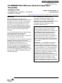
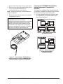
Dimensions
See Figure 1 for dimensions and physical features of
the FX-WRZRMT10K-0 Wireless Remote Temperature
Transmitter and the associated TE-6300 Series
Temperature Sensor.
Special Tools Needed
• 1/16 in. (1.6 mm) Allen-head adjustment tool
(Johnson Controls T-4000-119; order separately)
for the tamper-resistant set screw that secures the
transmitter to the mounting base
• 1/8 in. (3 mm) blade screwdriver for making wiring
connections to the terminal block on the transmitter
Compliance Statement (Part 15.19)
This device complies with Part 15 of the FCC Rules.
Operation is subject to the following two conditions:
1. This device may not cause harmful interference,
and
2. This device must accept any interference
received, including interference that may cause
undesired operation.
Warning (Part 15.21)
Changes or modifications not expressly approved by
the party responsible for compliance could void the
user’s authority to operate the equipment.
Industry Canada Statement
The term IC before the certification/registration
number only signifies that the Industry Canada
technical specifications were met.
Le terme « IC » précédant le numéro d'accréditation/
inscription signifie simplement que le produit est
conforme aux spécifications techniques d'Industry
Canada.
Figure 1: FX-WRZRMT10K-0 and TE-6300
Dimensions and Physical Features, in./mm
Signal
Test Button
Tamper Resistant
Set Screw
4-23/32
120
1-1/2
38
°F/°C
Button
FIG:dmnsns
3-5/32
80
10 ft (3 m)
Plenum-Rated Cable
3
76
1/4 in. (6 mm)
Outside Diameter
Back of Base
to Front of
Protrusion

FX-WRZRMT10K-0 Wireless Remote Temperature Transmitter Installation Guide 3
• coin for unlocking the transmitter housing from the
mounting base locking tab
Mounting
The FX-WRZRMT10K-0 Wireless Remote
Temperature Transmitter can be surface mounted
using the adhesive tape pieces affixed to the back of
the transmitter. The transmitter can also be mounted
on metal surfaces using a Johnson Controls
MAGNET-BASE-PLW Magnetic Backplate (order
separately).
To mount the TE-6300 Series Temperature Sensor,
refer to the installation instructions included with the
device.
Note: If another manufacturer’s 10k ohm thermistor
sensor is used with the FX-WRZRMT10K-0 Wireless
Remote Temperature Transmitter, the sensor must be
mounted within 10 ft (3 m) of the transmitter.
Location Considerations
When locating the temperature transmitter:
• Mount the transmitter vertically, for ease of reading
the Liquid Crystal Display (LCD) on the face of the
unit.
• Locate the transmitter on the same building level
as the nearest FX-ZFR1811 Router or
FX-WRZ7850-0 Receiver.
• For best signal transmission, locate the transmitter
at least 2 in. (51 mm) away from any metal
obstructions.
• Wherever possible, locate the transmitter in the
direct line of sight to the FX-ZFR1811 Router or
FX-WRZ7850-0 Receiver. Signal transmission is
best if the path between the transmitter and the
router or receiver is as direct as possible. Line of
sight is desirable but not required, as long as the
path is not blocked by large metal objects.
• Avoid metal obstructions (including equipment
rooms and elevator shafts) and concrete or
brick walls between the transmitter and the
FX-ZFR1811 Router or FX-WRZ7850-0 Receiver.
• Do not mount the transmitter closer than
2 ft (0.61 m) or farther than 100 ft (30 m) from the
FX-ZFR1811 Router, or 150 ft (45 m) from the
FX-WRZ7850-0 Receiver.
• The recommended indoor line-of-sight
transmission range between the transmitter and
the FX-ZFR1811 Router is 50 ft (15 m).
• Run the temperature sensor wire lead to the
transmitter, supporting the wire lead along the way
as necessary. This wire lead should not exceed
10 ft (3 m) in length.
Installing the FX-WRZRMT10K-0 Wireless
Remote Temperature Transmitter
The FX-WRZRMT10K-0 Wireless Remote
Temperature Transmitter can be surface mounted
using the double-sided adhesive foam tape
factory-installed on the back of the device. To mount
the transmitter base with adhesive foam tape:
1. Clean the desired mounting surface to ensure that
the adhesive foam tape sticks to the surface.
Note: The mounting surface, mounting base, and
ambient temperature must be at least 50°F (10°C)
when mounting the transmitter base with adhesive
foam tape.
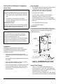
2. Remove the transmitter housing from its mounting
base (Figure 2).
Figure 2: Removing the Transmitter Housing
from its Mounting Base
(Reverse the Steps to Reinstall the Housing)
Tabs
1. Loosen (but do not remove)
the tamper-resistant set screw
on the locking tab of the
mounting base.
2. Insert a coin into the slot
on the top of the transmitter
housing, and depress the
locking tab on the mounting
base to release the housing.
FIG:trnsmttr_rmvl
4. Pull the bottom of the transmitter housing
down and off the tabs on the mounting base.
3. Swing the
transmitter
housing off
the mounting
base.
Mounting
Base
Transmitter
Housing

FX-WRZRMT10K-0 Wireless Remote Temperature Transmitter Installation Guide4
3. Peel off the protective paper from one side of the
factory-installed strips of adhesive foam tape on
the back of the mounting base.
4. When positioned correctly, the arrow between the
terminal slots on the inside of the mounting base
should point up. Ensure that the mounting base is
upright (tamper-resistant set screw on top) and
press the base firmly onto the clean mounting
surface.
5. See Connecting the TE-6300 Series Temperature
Sensor to the FX-WRZRMT10K-0 Wireless
Remote Temperature Transmitter.
Removing a Mounting Base Installed with
Double-Sided Adhesive Foam Tape
To remove or relocate a transmitter mounted with
double-sided adhesive foam tape:
1. Remove the transmitter housing from its mounting
base (Figure 2).
2. Remove the mounting base from the mounting
surface by carefully twisting the base off of the
surface.
3. Remove the adhesive foam tape from the mounting
base and clean the mounting base to remove any
leftover adhesive.
Note: New double-sided adhesive foam tape is
required to remount the base on the surface; use
Can-Do National Tape (Code No. 99116) adhesive
foam tape or its equivalent.
Connecting the TE-6300 Series Temperature
Sensor to the FX-WRZRMT10K-0 Wireless
Remote Temperature Transmitter
To connect the TE-6300 Series Temperature Sensor to
the FX-WRZRMT10K-0 Wireless Remote Temperature
Transmitter:
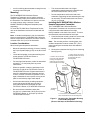
1. Feed the wire lead through the hole on the bottom
edge of the transmitter housing.
2. Loop the wire lead through the strain relief bushing
(included with the transmitter) as shown in
Figure 3, just inside the bottom edge of the
transmitter housing.
Note: The strain relief bushing is designed to
accommodate wire sizes ranging from 1/16 to 3/16 in.
(2 to 5 mm) in diameter.
Figure 3: Looping the Wire Lead through the
Strain Relief Bushing
1
2
3
4
FIG:strn_rlf_bshng

FX-WRZRMT10K-0 Wireless Remote Temperature Transmitter Installation Guide 5
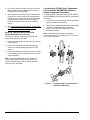
3. Remove the terminal block from the circuit board.
4. Secure the wire ends to the terminal block using a
1/8 in. (3 mm) blade screwdriver. The
recommended torque is 3 lb ft (4 N·m).
Note: The wiring connections on the terminal block
are interchangeable.
5. Reinstall the terminal block onto the circuit board
as illustrated in Figure 4.
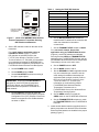
Preparing the FX-WRZRMT10K-0 Wireless
Remote Temperature Transmitter for
Operation
To prepare the FX-WRZRMT10K-0 Wireless Remote
Temperature Transmitter for operation, and to reinstall
the transmitter housing on its mounting base:
1. Place the appropriate DIP switch overlay (based
on the application) over the DIP switches. See
Figure 5 through Figure 7.
IMPORTANT: Do not power up the
FX-WRZRMT10K-0 Wireless Remote
Temperature Transmitter until a receiver or controller
is installed and operating within the same Radio
Frequency (RF) range. If this condition is not met,
the transmitter uses a higher-than-normal battery
current as it attempts to find a receiver or controller
within range, resulting in reduced battery life.
Figure 4: Connecting the TE-6300 Series
Temperature Sensor to the FX-WRZRMT10K-0
Wireless Remote Temperature Transmitter
FIG:prb_wrng
Figure 5: Mesh Network Application
DIP Switch Overlay
FIG:zfr1811_msh
Figure 6: Non-mesh Network,
One-to-One Application
DIP Switch Overlay
FIG:wrz78xx_non_msh

FX-WRZRMT10K-0 Wireless Remote Temperature Transmitter Installation Guide6
2. Set the DIP switches located on the back of the
transmitter.
For a mesh network application using an
FX-ZFR1811 Router (Figure 5), set the
DIP switches as indicated. Refer to the
FX-ZFR Series Wireless Field Bus System
Technical Bulletin (LIT-12011660) for information
on commissioning multiple FX-WRZRMT10K-0
Wireless Remote Temperature Transmitters in an
FX-ZFR1800 Series Wireless Field Bus System.
a. Set the POWER switch to OFF.
b. Set the MODE switch to Mesh.
c. Set the PAN OFFSET switches according to
the job or system plans.
d. Set the ZONE DIP switches to match the
Zone Number in the Facility Explorer Controller
Configuration Tool (CCT) software. Each Zone
Number corresponds to the SA Bus Address
as shown in Table 1.
e. Set the MSTP ADDRESS DIP switches to
match the MS/TP address of the controller with
which the transmitter is intended to
communicate.
f. Set the TRANSMIT LEVEL switch to 10mW.
For a non-mesh network, One-to-One
application using an FX-WRZ7850-0 Receiver
(Figure 6), set the DIP switches as indicated,
ensuring that the AREA and TRANSMITTER ID
switches on the FX-WRZ7850-0 Receiver and the
FX-WRZRMT10K-0 Wireless Remote Temperature
Transmitter(s) are set to the same value.
a. Set the POWER switch to OFF.
b. Set the MODE switch to 1 to 1.
c. Set the SENSOR # to 199 for applications with
only one transmitter per controller. Use the
other settings for additional transmitters in
applications with a single controller. Refer to
the One-to-One Wireless Sensing System
Technical Bulletin (LIT-12011663) for
information on commissioning multiple
FX-WRZRMT10K-0 Wireless Remote
Temperature Transmitters in an
FX-WRZ7850-0 One-to-One Wireless Room
Temperature Sensing System.
d. Set the AREA switches to match the
AREA switch on the FX-WRZ7850-0 Receiver.
e. Set the TRANSMITTER ID switches to match
the TRANSMITTER ID on the FX-WRZ7850-0
Receiver.
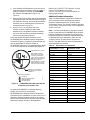
3. Install two AA alkaline batteries (supplied) into the
battery compartment on the back of the transmitter.
Ensure that the batteries are installed in the proper
polarity (Figure 7).
IMPORTANT: Ensure that the PAN OFFSET is
the same for each FX-ZFR1810 Coordinator,
FX-FR1811 Router, and FX-WRZRMT10K-0
Wireless Remote Temperature Transmitter in a
mesh network.
Figure 7: Back of FX-WRZRMT10K-0 Wireless
Remote Temperature Transmitter Showing
DIP Switches and Batteries
AA Alkaline Battery
A
A
A
l
k
a
l
i
n
e
B
a
t
t
e
r
y
Insert two AA alkaline
batteries in battery
compartment.
FIG:bck_wrz_str0000_0
Place
DIP switch
overlay
here.
Table 1: Setting the ZONE DIP Switches
Zone Number SA Bus Address
0 199
1 200
2 201
3 202
4 203
5 204
6 205
7 206
8 207

FX-WRZRMT10K-0 Wireless Remote Temperature Transmitter Installation Guide 7
4. If the address DIP switches are set to the correct
positions and the temperature sensing system is
ready for operation or testing, set the POWER
DIP switch to the ON position (Figure 5 or
Figure 6).
5. Align the tabs on the bottom edge of the transmitter
mounting base with the slots on the bottom edge of
the transmitter housing, and rotate the transmitter
assembly onto its mounting base. (Reverse the
procedure shown in Figure 2.)
6. Use a 1/16 in. (1.6 mm) Allen wrench or
Johnson Controls T-4000-119 Allen-Head
Adjustment Tool to tighten the tamper-resistant
set screw and secure the transmitter assembly
onto its mounting base (Figure 2).
Press and release the signal test button on the
FX-WRZRMT10K-0 Wireless Remote Temperature
Transmitter (Figure 1) to initiate a signal strength test
with the associated FX-ZFR1811 Router or
FX-WRZ7850-0 Receiver. The signal strength is shown
on the LCD on the face of the transmitter (Figure 8).
An optional FX-WRZSST-110 Wireless Sensing
System Tool can also be used with the
FX-WRZRMT10K-0 Wireless Remote Temperature
Transmitter prior to installation as a site survey tool, to
determine potential installation locations for system
devices and to determine the wireless signal strength
between the system devices in the application.
Refer to the FX-WRZSST-110 Wireless Sensing
System Tool Installation Instructions
(Part No. 24-10563-20) for more information on
testing signal strength.
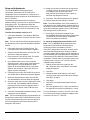
Additional Product Information
Table 2 includes Negative Temperature Coefficient
(NTC) thermistor sensor temperature/resistance
response characteristics for the TE-6300 Series
Temperature Sensor. The values included in this table
can be used to verify the accuracy of the temperature
sensor in the field.
Note: If another manufacturer’s 10k ohm thermistor
sensor is used with the FX-WRZRMT10K-0 Wireless
Remote Temperature Transmitter, the values for the
temperature/resistance response characteristics may
be different than those indicated in Table 2 for the
Johnson Controls TE-6300 Series Temperature
Sensor. This difference may cause the transmitter to
read temperatures incorrectly.
Figure 8: FX-WRZRMT10K-0 Wireless Remote
Temperature Transmitter LCD
FIG:lcd_dsply
Digital Readout for 104°F
Note: Digital readouts
above 99.9°F are whole
numbers (no decimals),
where the first and second
digits are full size and the
third digit is half size.
Digital readouts for Celsius
temperatures are normal
size and include decimals.
= No Signal
= Weak or Marginal Signal
= Adequate Signal
= Excellent Signal
Signal Strength Graph:
Indicates Loss of Network
Connection When Symbol
Flashes On
°F
Table 2: Temperature vs. Resistance
Temperature, °F (°C) Resistance, ohms
-50 (-46) 489,981
-40 (-40) 366,185
-30 (-34) 233,990
-20 (-29) 165,085
-10 (-23) 117,978
0 (-18) 85,349
10 (-12) 62,464
20 (-7) 46,221
30 (-1) 34,562
40 (4) 26,103
50 (10) 19,903
60 (16) 15,313
70 (21) 11,883
80 (27) 9,298
90 (32) 7,333
100 (38) 5,827
110 (43) 4,663
120 (49) 3,757
130 (54) 3,048
140 (60) 2,488
150 (66) 2,043
160 (71) 1,687
170 (77) 1,401

FX-WRZRMT10K-0 Wireless Remote Temperature Transmitter Installation Guide8
Setup and Adjustments
The FX-WRZRMT10K-0 Wireless Remote
Temperature Transmitter and TE-6300 Series
Temperature Sensor combination is configured as a
NetZoneSensor (also identified as Zone NetSensor) in
the CCT software.
The following steps describe how to define the
hardware setting, as well as how to adjust the default
temperature limits. This adjustment allows the
FX-WRZRMT10K-0 Wireless Remote Temperature
Transmitter to properly report the temperature to the
controller.
To define the hardware setting in CCT:
1. Click Define Hardware. The Hardware Definition
Wizard opens with the Controller Selection screen
active.
Note: You can also use the Define Hardware option of
the Operations menu to open the Hardware Definition
Wizard.
2. Click Select next to the Field Device box. The
Controller Device Selection dialog box appears.
3. Select the desired field device and click OK. The
Add Device dialog box appears.
4. Enter the device name and click OK. The device
name appears in the Field Device box.
5. In the SA Bus Devices box of the Controller
Selection screen, verify that the Zone NetSensor
option appears. The Zone NetSensor option
applies to the FX-WRZRMT10K-0. If this option
appears, skip to Step 9. If this option does not
appear, continue with Step 6.
6. Click Add Device next to the SA Bus Devices box.
The SA Bus Device Selection dialog box appears.
7. Select the NetZoneSensor option and click OK.
The Add NetSensor Devices dialog box appears.
8. Select the check box next to the application (Zone)
and click OK. The Hardware Definition Wizard -
Controller Selection screen re-appears with the
Zone NetSensor device in the SA Bus Devices
box.
9. Click Next. The Hardware Definition Wizard - Point
Assignment screen appears.
Note: CCT automatically assigns the points based on
the selections made in the Controller Selection screen.
The Zone temperature input point does not appear on
the Point Assignment screen because this point is
assigned to the SA Bus.
10. Assign your points if needed. Use the right arrow
to assign a point to an object. Use the left arrow
to unassign a point from an object. Use
drag-and-drop functionality to move a point up
and down the Assigned Points list.
11. Click Next. The Network Settings screen appears.
12. Review and modify the settings, if needed.
Note: The default address of the Zone NetSensor is
199 (appears in the SA Bus Device Settings section of
the screen). Be aware that this address is not the same
as the Device Address (appears in the Field Device &
Bus Settings section of the screen).
13. Click Finish. The hardware settings for the
FX-WRZRMT10K-0 Wireless Remote Temperature
Transmitter and TE-6300 Series Temperature
Sensor combination are defined.
To adjust the default temperature limits in CCT:
Note: The FX-WRZRMT10K-0 Wireless Remote
Temperature Transmitter and TE-6300 Series
Temperature Sensor combination uses the
Zone (ZN-T) temperature input point. All other points
associated with temperature (for example, setpoint,
occupancy mode, and fan status) are not applicable to
the FX-WRZRMT10K-0 Wireless Remote Temperature
Transmitter and TE-6300 Series Temperature Sensor
combination. The Min Value on an engine must be set
to greater than or equal to -9°F (-23°C) to prevent
unreliable status indicators.
1. With the Control tab active, right-click the
ZN-T input and select View Details. The Details
dialog box appears.
2. Click Edit.
3. Change the Max Value setting to 158.0 deg F
(70 deg C) and verify that the Min Value setting is
32.0 deg F (0 deg C).
4. Click Apply.
5. Click Close. The default temperature limits are
adjusted.
6. Save the application (File > Save), and download
the application to the device (Operations > Load).
For more information on how to use CCT, refer to the
User Interface and Defining Hardware chapters of the
Controller Tool Help (LIT-12011147).

FX-WRZRMT10K-0 Wireless Remote Temperature Transmitter Installation Guide 9
Repair Information
If the FX-WRZRMT10K-0 Wireless Remote
Temperature Transmitter fails to operate within its
specifications, replace the unit. For a replacement
transmitter, contact the nearest Johnson Controls
representative.
The two AA alkaline batteries supplied with the
FX-WRZRMT10K-0 Wireless Remote Temperature
Transmitter typically have a life of 5 years or more. The
transmitter reports a low battery condition to the
receiver or controller, which relays the low battery
condition to the Facility Explorer system. The low
battery condition is also shown on the LCD on the face
of the transmitter.
Replace the transmitter batteries with two high-quality
AA alkaline batteries as necessary, ensuring that the
batteries are installed in the proper polarity (Figure 7).
Note: When replacing batteries, both batteries should
be replaced at the same time. Batteries removed from
this device must be recycled or disposed of in
accordance with local, national, and regional
regulations. Only certified technicians or qualified
building maintenance personnel should service
Johnson Controls products. Lithium batteries with a
maximum cell voltage of 1.5 volts can be substituted to
extend the period between replacing the batteries.
Do not mix lithium and alkaline batteries in this device.
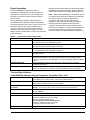
Technical Specifications
Table 3: Accessories Ordering Information
Code Number Description
TE-6361A-1 Johnson Controls 10k ohm Type II Thermistor Sensor;
8 in. (203 mm) Duct Probe, Adjustable Enclosure
TE-6361V-2 Johnson Controls 10k ohm Type II Thermistor Sensor;
8 in. (203 mm) Duct Probe, Flange Mount Enclosure
TE-636GV-2 Johnson Controls 10k ohm Type II Thermistor Sensor;
4 in. (102 mm) Duct Probe, Flange Mount Enclosure
TE-636S-1 Johnson Controls 10k ohm Type II Thermistor Sensor;
Strap-Mount Probe
FX-WRZSST-110 Wireless Sensing System Tool: For Use with an FX-WRZRMT10K-0 Wireless Remote
Temperature Transmitter, to Function as a Site Survey Tool for the FX-WRZ Series
One-to-One Wireless Room Sensing System, or for the FX-ZFR1800 Wireless Field Bus
System
MAGNET-BASE-PLW Magnetic Backplate for Mounting the Transmitter on Metal Surfaces; 5 Magnetic
Backplates per Package
T-4000-119 Allen-Head Adjustment Tool: 1/16 in. (1.6 mm), for the Tamper-Resistant Set Screw That
Secures the Temperature Transmitter to the Mounting Base; 30 Tools per Package
FX-WRZRMT10K-0 Wireless Remote Temperature Transmitter (Part 1 of 2 )
Power Requirements 3 VDC Supplied by Two 1.5 VDC AA Alkaline Batteries (Included with Transmitter);
Typical Battery Life: 5 Years or More; 7 Years Using Lithium Batteries
Addressing DIP Switches, Field Adjustable;
MS/TP Address, Network Number, and Zone Address
Transmitter Ambient
Conditions
Operating: 23°F to 111°F (-5°C to 44°C), 5% RH to 95% RH, Noncondensing
Storage:
-4°F to 140°F (-20°C to 60°C), 5% RH to 95% RH, Noncondensing
RF Band Direct-Sequence, Spread-Spectrum;
2.4 GHz ISM Band
Transmission Power 10 mW Maximum
Transmission Range Mesh Network Application:
100 ft (30 m) Maximum Indoor Line
of Sight;
50 ft (15 m) Practical Average Indoor
Non-mesh Network, One-to-One Application:
150 ft (45 m) Maximum Indoor Line of Sight;
100 ft (30 m) Practical Average Indoor
Transmissions Every 120 Seconds (±20 Seconds)

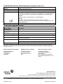
Published in U.S.A. www.johnsoncontrols.com
FX-WRZRMT10K-0 Wireless Remote Temperature Transmitter Installation Guide10
Johnson Controls® is a registered trademark of Johnson Controls.
All other marks herein are the marks of their respective owners. © 2019 Johnson Controls
Building Efficiency
507 E. Michigan Street, Milwaukee, WI 53202
Temperature System Accuracy ±1.8F°/±1.0C° Over the Range of 32°F to 158°F (0°C to 70°C)
Materials NEMA 1 White Plastic Housing
Mounting Surface Mounted Using Factory-Installed, Double-Sided Adhesive Foam Tape
Compliance United States:
Transmission Complies with FCC Part 15.247 Regulations for Low Power Unlicensed
Transmitters; Transmitter FCC Identification: TFB-MATRIXL or OEJ-WRZRADIO
Canada:
Industry Canada IC: 5969A-MATRIXL or 279A-WRZRADIO
Europe:
CE Mark – Johnson Controls declares that this product is in compliance
with the essential requirements and other relevant provisions of the RED, EMC, LVD,
and RoHS Directive.
Shipping Weight 0.55 lb (0.25 kg)
TE-6300 Series Temperature Sensors
Sensor Type 10k ohm Johnson Controls Type II Thermistor Sensor
Sensor Thermal
Characteristics
See Table 2
Sensor Temperature
Coefficient
Nonlinear 10k ohm NTC Thermistor
Electrical Connections 22 AWG (0.6 mm Diameter) x 10 ft (3 m) Long Plenum-Rated Cable (White Leads)
Probe Materials Stainless Steel
Mounting Mount within 10 ft (3 m) of the FX-WRZRMT10K-0 Wireless Remote
Temperature Transmitter
Operating Temperature Limits Cable: -50°F to 140°F (-46°C to 60°C)
Probe: -50°F to 220°F (-46°C to 104°C)
Shipping Weight 0.2 lb (0.09 kg)
The performance specifications are nominal and conform to acceptable industry standard. For application at conditions beyond these
specifications, consult the local Johnson Controls office. Johnson Controls shall not be liable for damages resulting from misapplication or
misuse of its products.
European Single Point of Contact: NA/SA Single Point of Contact: APAC Single Point of Contact:
JOHNSON CONTROLS
WESTENDHOF 3
45143 ESSEN
GERMANY
JOHNSON CONTROLS
507 E MICHIGAN ST
MILWAUKEE WI 53202
USA
JOHNSON CONTROLS
C/O CONTROLS PRODUCT
MANAGEMENT
NO. 22 BLOCK D NEW DISTRICT
WUXI JIANGSU PROVINCE 214142
CHINA
FX-WRZRMT10K-0 Wireless Remote Temperature Transmitter (Part 2 of 2 )
-
 1
1
-
 2
2
-
 3
3
-
 4
4
-
 5
5
-
 6
6
-
 7
7
-
 8
8
-
 9
9
-
 10
10


Johnson Controls FX-WRZRMT10K-0 Guide d'installation
- Taper
- Guide d'installation
dans d''autres langues
Documents connexes
-
Johnson Controls WRZ-7860-0 Installation Instructions Manual
-
-
-
-
-
-
-
-
-