La page est en cours de chargement...

Read all instructions
before assembly and use.
KEEP INSTRUCTIONS FOR
FUTURE USE.
Lisez toutes les instructions avant
l’assemblage et l’utilisation.
CONSERVEZ LES INSTRUCTIONS
POUR UN USAGE ULTERIEUR.
Lea todas las instrucciones
antes de ensamblar y usar.
MANTENGA LAS INSTRUCCIONES
PARA SU USO FUTURO.
When contacting Delta Consumer Experience Center please reference the above information. Before contacting
Delta Consumer Experience Center please ensure that the information above matches the information found on the
label on the Back Panel, please reference the information found on the product when contacting Delta Consumer
Experience Center.
Lorsque vous contactez le Service client de Delta, veuillez faire référence aux informations ci-dessus. Avant de
contacter le Service client de Delta, veuillez vous assurer que les informations ci-dessus correspondent aux
informations indiquées sur l’étiquette qui se trouve sur panneau arrière; veuillez faire référence aux informations
indiquées sur le produit lorsque vous contactez le Service client de Delta.
Al contactar al servicio al cliente de Delta, entregue la información anteriormente mencionada. Antes de
contactar al servicio de atención al cliente de Delta, asegúrese de que la información anteriormente mencionada
calza con la que aparece en la etiqueta en panel trasero; al contactar al centro de atención al cliente de Delta,
mencione la información que aparece en el producto.
CONSUMER EXPERIENCE CENTER
Simmons Juvenile Furniture, A division of Children’s Products LLC |114 West 26th Street New York, NY 10001
(646) 435-8727 | [email protected] | www.DeltaChildren.com
Style #:
Lot:
Date:
___________
___________
___________
A
REV
This product is not intended for institutional or commercial use.
Ce produit ne pas destine a un usage institutionnel ou commercial.
Este producto no esta hecho para uso institucional o comercial.
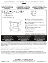
ADULT ASSEMBLY REQUIRED
Due to the presence of small parts during assembly, keep out
of reach of children until assembly is complete.
L’ASSEMBLAGE DOIT ETRE FAIT
PAR UN ADULTE
A cause de la presence de petites pieces, pendant l’assemblage
gardez hors de portee des enfants jusqu'a ce que celui-ci soit
termine.
DEBE SER ENSAMBLADO
POR UN ADULTO
Debido a la presencia de piezas pequeñas durante el
ensamblaje, mantenga fuera del alcance de los niños hasta que
complete el ensamblaje.
NEED EXTRA HELP?
We make assembly easy with
our tips & tricks video
https://www.deltachildren.com/
pages/instructions
BESOIN D'AIDE SUPPLÉMENTAIRE?
Nous facilitons l'assemblage avec
nos trucs et astuces vidéo
https://www.deltachildren.com/
pages/instructions
¿NECESITA AYUDA EXTRA?
Hacemos el montaje fácil con
nuestros consejos y trucos video
https://www.deltachildren.com/
pages/instructions
June 11, 2019, 29330, R2
©2019 DELTA ENTERPRISE CORP.
ASSEMBLY INSTRUCTIONS • INSTRUCTIONS DE MONTAGE • INSTRUCCIONES DE MONTAJE
Dresser
Commode
Cómoda

CONSEILS POUR FAIRE DORMIR
VOTRE BÉBÉ EN TOUTE SÉCURITÉ
Conseils de l’AAP: Placez toujours votre bébé
sur le dos pour dormir. Consultez votre médecin.
Visitez Deltachildren.Com/Pages/Crib-Safety-Tips pour plus d’information
NE déposez aucun objet
dans le Lit de Bébé
Votre bébé doit dormir
sur un matelas ferme.
Des oreillers et
couvertures ont parfois
été responsables
d’étouffements de
nourrissons. N’en utilisez
JAMAIS dans un lit de
bébé.
Les lits d’adultes ne sont
pas un lieu sûr pour les
bébés: NE dormez
JAMAIS ensemble.
NE placez JAMAIS le Lit de
Bébé à proximité d’une
fenêtre ou de tentures.
L’endroit le plus sûr pour
faire dormir votre bébé,
c’est dans un Lit de
Bébé approuvé par
JPMA.
Des pièces manquantes
ou cassées?APPELEZ Delta
Children Consumer Care.
Lisez tous les
avertissements et
respectez toutes les
consignes de sécurité.
ASSEMBLY INSTRUCTIONS • INSTRUCTIONS DE MONTAGE • INSTRUCCIONES DE MONTAJEASSEMBLY INSTRUCTIONS • INSTRUCTIONS DE MONTAGE • INSTRUCCIONES DE MONTAJEASSEMBLY INSTRUCTIONS • INSTRUCTIONS DE MONTAGE • INSTRUCCIONES DE MONTAJE
4

LE RENVERSEMENT DU MEUBLE PEUT ENTRAÎNER DES
BLESSURES GRAVES OU MORTELLES.
NE déposez PAS de
postes de télévision ou
d’autres objets lourds sur
des meubles de
chambre à coucher ou
de chambre d’enfants.
Utilisez TOUJOURS les
dispositifs de
non-renversement
fournis.
NE laissez JAMAIS les
enfants monter sur ou se
suspendre aux tiroirs,
portes et ou tablettes.
Placez les objets les
plus lourds dans les
tiroirs du bas.
N’OUVREZ JAMAIS plus
d’un tiroir en même
temps
NE laissez PAS les tiroirs
ouverts lorsque vous
ne les utilisez pas.
Visitez Deltachildren.Com/Pages/Leaders-In-Safety pour plus d’information
ASSEMBLY INSTRUCTIONS • INSTRUCTIONS DE MONTAGE • INSTRUCCIONES DE MONTAJEASSEMBLY INSTRUCTIONS • INSTRUCTIONS DE MONTAGE • INSTRUCCIONES DE MONTAJE
Lisez tous les
avertissements et
respectez toutes les
consignes de sécurité.
Des pièces manquantes
ou cassées?APPELEZ Delta
Children Consumer Care.
CONSEILS DE SÉCURITÉ RELATIFS
AUX MEUBLES
5

ASSEMBLY INSTRUCTIONS • INSTRUCTIONS DE MONTAGE • INSTRUCCIONES DE MONTAJEASSEMBLY INSTRUCTIONS • INSTRUCTIONS DE MONTAGE • INSTRUCCIONES DE MONTAJEASSEMBLY INSTRUCTIONS • INSTRUCTIONS DE MONTAGE • INSTRUCCIONES DE MONTAJE
DELTA CHILDREN
@deltachildren
SUIVEZ NOUS POUR AVOIR PLUS DE CHANCES DE GAGNER /
SÍGANOS PARA TENER MAS CHANCES DE GANAR
SCANNEZ ICI / ESCANEE AQUÍ
Pour plus d'informations et
pour voir tous nos produits
Para más información y para
ver todos nuestros productos
ÉCONOMISEZ BEAUCOUP AVEC
AHORRE MUCHO CON
Visitez Deltachilren.com Pour Commencer Vos Achats
Visita Deltachilren.com Para Comenzar A Comprar
FAMILLE DELTA
Bienvenue dans la
Voici Notre Cadeau Pour Vous
Votre Prochain Achat Chez
*Subject to Change
*Exclusions Apply
*Des exclusions s’appliquent
*Sujet à changement
Aquí Está Nuestro Regalo Para Usted
FAMILIA DELTA
Bienvenido a la
Su Próxima Compra En
DeltaChildren.com
DELTA10
UTILISEZ LE CODE:
UTILICE EL CÓDIGO:
ECRIVEZ UN COMMENTAIRE CLIENT pour ce produit sur le site web du magasin où il a été acheté
CALIFIQUE EL PRODUCTO en la página web de la tienda donde haya sido comprado
1
FAITES UNE CAPTURE D’ECRAN de votre commentaire client et mettez la en ligne sur www.DeltaChildren.com/Review
HAGA UNA CAPTURA DE PANTALLA de su calificación y cárguela a la pagina www.DeltaChildren.com/Review
2
C’EST AUSSI SIMPLE QUE ÇA! Dès que c’est fait vous serez instantanément INSCRIT POUR GAGNER 2500$
ES ASÍ DE FÁCIL! En cuanto lo envíe ya estará instantáneamente PARTICIPANDO PARA GANAR $2.500
3
REGLEMENT DE PARTICIPATION / REGLAS PARA PARTICIPAR
LAISSEZ UN COMMENTAIRE CLIENT POUR GAGNER $2500
CALIFIQUE EL PRODUCTO PARA GANAR $2500
9

WARNING
Serious or fatal crushing injuries can occur from furniture tip-over. To help
prevent tip-over:
.
Install tipover restraint provided.
.
Place heaviest items in the lowest drawers.
.
Do not set TV's or other heavy objects on top of this product, unless the product
is specifically designed to accommodate them.
.
Never allow children to climb or hang on drawers, doors,or shelves.
.
Never open more than one drawer at a time.
Use of tip-over restraints may only reduce, but not eliminate, the risk of
tip-over.
AVERTISSEMENT
Des blessures sérieuses ou mortelles dues à un écrasement peuvent
survenir lorsqu’un meuble bascule. Pour prévenir ces accidents:
.
Installez le dispositif anti bascule fourni.
.
Placez les articles les plus lourds dans les tiroirs inferieurs.
.
Ne PAS poser une TV ou autres objets lourds sur ce produit à moins que le
produit soit spécifiquement conçu pour les recevoir.
.
Ne jamais permettre à un enfant de grimper ou s’accrocher aux tiroirs, portes
ou étagères.
.
Ne jamais ouvrir plus d’un tiroir a la fois
L’utilisation du système anti-basculement peut seulement diminuer mais
pas complètement éliminer le risque de basculement.
ADVERTENCIA
Pueden producirse lesiones graves o mortales por aplastamiento al
volcarse muebles. Para evitar vuelcos:
.
Instalar el dispositivo anti-vuelcos que viene incluido.
.
Coloque los artículos de mayor peso en los cajones inferiores.
.
No coloque televisores ni ningún otro objeto pesado encima de este producto, a
menos de que el producto esté específicamente diseñado para ese propósito.
.
Nunca permita que los niños trepen sobre cajones, puertas o baldas de
estantería ni que se cuelguen de ellos.
.
Nunca abra más de un cajón al mismo tiempo.
El uso de herramientas de contención de vuelcos tan solo puede reducir,
pero no eliminar, el riesgo de vuelco.
10

L. Top Panel x1
Panneausupérieur
Panel superior
#29314
E. Top Front Rail x1
Barre avant supérieur
Barra frontal superior
#29315
K. Back Weight x2
Poids arrière
Peso trasero
#29321
G. Bottom Front Rail x1
Barre avant inférieur
Barra frontal inferior
#29317
C. Top Center Panel x2
Panneau central supérieur
Panel central superior
#29312
M. Back Panel x1
Panneau arrière
Panel Trasero
#29322
H. Middle Front Rail x1
Barre Central Avant
Barra Frontal Central
#29316
A. Left Side x1
Côté gauche
Lado izquierdo
#29310
B. Right Side x1
Côté droit
Lado derecho
#29311
D. Center Panel x1
Panneau central
Panel central
#29313
J. Top Back Rail x1
Barre arrière supérieur
Barra trasero superior
#29318
11
PARTS: MAKE SURE THAT ALL PRE-ASSEMBLED PARTS ARE TIGHT
PIÈCES : VÉRIFIEZ QUE TOUTES LES PIÈCES PRÉ-MONTÉES SONT BIEN SERRÉES.
PIEZAS: ASEGÚRESE DE QUE TODAS LAS PIEZAS PRE-ENSAMBLADAS ESTÁN BIEN APRETADAS.
ASSEMBLY INSTRUCTIONS • INSTRUCTIONS DE MONTAGE • INSTRUCCIONES DE MONTAJE

N. Middle Back Rail x1
Barre Central Arrière
Barra Trasero Central
#29319
F. Bottom Back Rail x1
Barre arrière inférieur
Barra trasero inferior
#29320
P. Top Drawer Side x6
Barre de tiroir supérieur
Barra de la gaveta superior
#29085
W. Drawer Support x7
Support du Tiroir
Soporte de la Gaveta
#29746
U. Top Drawer Front x3
Avant du Tiroir supérieur
Parte frontal de la Gaveta
superior
#29323
T. Bottom Drawer Front x4
Avant du Tiroir inférieur
Parte frontal de la
Gaveta inferior
#29326
R. Top Drawer Back x3
Arrière du tiroir supérieur
Parte posterior de la
gaveta superior
#29324
Z. Top Drawer Bottom x3
Fond du tiroir supérieur
Parte inferior de la gaveta superior
#29325
S. Bottom Drawer Back x4
Arrière du tiroir inférieur
Parte posterior de la
gaveta inferior
#29327
X. Bottom Drawer Bottom x4
Fond du tiroir inférieur
Parte inferior de la gaveta inferior
#29328
Y. Bottom Drawer Side x8
Barre de tiroir inférieur
Barra de la gaveta inferior
#29087
12
PARTS: MAKE SURE THAT ALL PRE-ASSEMBLED PARTS ARE TIGHT
PIÈCES : VÉRIFIEZ QUE TOUTES LES PIÈCES PRÉ-MONTÉES SONT BIEN SERRÉES.
PIEZAS: ASEGÚRESE DE QUE TODAS LAS PIEZAS PRE-ENSAMBLADAS ESTÁN BIEN APRETADAS.
ASSEMBLY INSTRUCTIONS • INSTRUCTIONS DE MONTAGE • INSTRUCCIONES DE MONTAJE

Parts: Hardware kits part#29329
Pièces: L'ensemble de quincaillerie - pièce n°29329
Piezas: El kit de herramientas - Pieza #29329
KK. Φ6x30mm Dowel x42
Cheville Φ6x30mm
Pasador Φ6x30mm
JJ. 20mm Screw x28
Vis 20mm
Tornillo 20mm
HH. 40mm Screw x35
Vis 40mm
Tornillo 40mm
LL. Plastic Barrel Nut x35
Écrou à portée cylindrique
en plastique
Tuercacilíndricaplástica
CC. 30mm Bolt x18
Boulon 30mm
Perno 30mm
BB. 55mm Bolt x16
Boulon 55mm
Perno 55mm
Phillips Screwdriver – Not included
Tournevis Phillips - non inclus
Destornillidor Phillips – no incluido
CAUTION: Do Not use a power screwdriver they can
cause screws to break or strip.
ATTENTION: Ne Pas utiliser un tournevis électrique
car les vis peuvent casser ou perdre leurs filets.
ATENCIÓN: No use un destornillador eléctrico ya
que puede causar que los tornillos se rompan o
rueden.
M4 Ballend Screwdriver
tournevis M4 à tête sphérique
destornillador M4 con cabeza de bola
M4 Allen Wrench
Clé Allen M4
Llave Allen M4
GG. Back Panel Screw x12
Vis pour Panneau Arrière
Tornillo de Panel Trasero
EE. Crescent Washer x6
Rondelle en croissant
Arandela de media luna
NN.12mm Screw x42
Vis 12mm
Tornillo 12mm
PP. Knob / Bouton / Perilla x7
#27470
PP1. Knob
Bouton
Perilla
PP2. Knob Screw
Vis de Bouton
Tornillo para Perilla
YY. Short Screw x1
Vis Court
Tornillo corto
XX. Long Screw x1
Vis Longue
Tornillo Largo
TT. Washer x2
Rondelle
Arandela
ZZ. (1) Wall Strap/Sangle murale/Abrazadera
13
ASSEMBLY INSTRUCTIONS • INSTRUCTIONS DE MONTAGE • INSTRUCCIONES DE MONTAJEASSEMBLY INSTRUCTIONS • INSTRUCTIONS DE MONTAGE • INSTRUCCIONES DE MONTAJE

1. Insert the Dowels in the Rail into the holes in
the Post.
1. Insérer les chevilles dans le rail dans les orifices
dans le poteau.
1. Inserte los pasadores del Riel en los agujeros
del Poste.
2. Insert the Bolt into the slot. Turn clockwise
with fingers or the Ball End Screwdriver
provided. DO NOT fully tighten, leave 1/2”
(12mm) exposed.
2. Insérez le boulon dans la fente. Tournez dans
le sens des aiguilles d’une montre à l’aide des
doigts ou de la tournevis à tête sphérique. Ne
Pas serrer complètement et laisser 12 mm (1/2
pouces) exposés.
2. Inserte el perno en la ranura. Gírelo en el
sentido de las agujas del reloj con los dedos o
con el destornillador con cabeza de bola. NO
lo apriete del todo, deje 1/2" (12 mm) fuera.
3. Slide the Crescent Washer over the
exposed bolt, behind the head of the bolt.
3. Glissez la rondelle en croissant sur l'écrou
exposé, derrière la tête de l'écrou.
3. Abrace la parte del Perno que quedó
fuera, debajo de la cabeza del mismo, con
la Arandela de media luna.
Hardware System - Review Before Assembly
Quincaillerie – Lire Avant D’effectuer Le Montage
Revise Antes De Armar- Elementos De Fijacion Y Ensamble
EE. Crescent Washer
Rondelle en Croissant
Arandela de Media Luna
BB. 55mm Bolt
Boulon 55mm
Perno 55mm
14
ASSEMBLY INSTRUCTIONS • INSTRUCTIONS DE MONTAGE • INSTRUCCIONES DE MONTAJEASSEMBLY INSTRUCTIONS • INSTRUCTIONS DE MONTAGE • INSTRUCCIONES DE MONTAJE

Install (1) bolt and (1) crescent washer at a time. Tighten until it looks like the picture.
Installez (1) boulon et (1) rondelle en croissant à la fois. Serrez jusqu'à ce que cela ressemble à
l'image.
Instale (1) perno y (1) Arandela de media luna al mismo tiempo. Apriételos hasta que quede
como en la ilustración.
Ensure all bolts are tight with Allen wrench.
Serrez à l’aide de la clé Allen.
Apriételo con la llave Allen.
Tighten the bolt with the ball end
screwdriver.
Serrez à l’aide de la Tournevis à tête
sphérique.
Apriételo con el Destornillador hcon cabeza
de bola.
15
ASSEMBLY INSTRUCTIONS • INSTRUCTIONS DE MONTAGE • INSTRUCCIONES DE MONTAJEASSEMBLY INSTRUCTIONS • INSTRUCTIONS DE MONTAGE • INSTRUCCIONES DE MONTAJE

CC. 30mm Bolt x4
Boulon 30mm
Perno 30mm
M4 Allen Wrench
Clé Allen M4
Llave Allen M4
KK. Φ6x30mm Dowel x8
Cheville Φ6x30mm
Pasador Φ6x30mm
BB. 55mm Bolt x4
Boulon 55mm
Perno 55mm
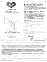
Fije la Barra frontal inferior (Pieza E), Barra trasero superior (Pieza J), Barra Frontal
Central(Pieza H) y Barra Trasero Central (Pieza N) al (2) Panel central superior (Pieza
C) utilizando (8) Pasadors (Pieza KK) (4) Pernos 55mm (Pieza BB) and (4) Pernos
30mm (Pieza CC) utilizando el llave Allen M4.
Attach Top Front Rail (Part E), Top Back Rail (Part J), Middle Front Rail (Part H) and Middle
Back Rail (Part N) to (2) Top Center Panel (Part C) using (8) dowels (Part KK), (4) 55mm
Bolt (Part BB) and (4) 30mm Bolts (Part CC) . Tighten all bolts with the M4 Allen Wrench.
Fixer le Barre avant supérieur (Pièce E), Barre arrière supérieur (Pièce J) , Barre Central
Avant (Pièce H) et le Barre Central Arrière (Pièce N) à (2) panneau central supérieur
(Pièce C) à l’aide de (8) chevilles (Pièce KK), (4) boulons 55 mm (Pièce BB) et (4) Boulons
30mm (Pièce CC). Serrer tous les boulons à l’aide de la clé Allen M4 .
Step 1
Étape 1
Paso 1
Parts and tools required to complete step
Pièces et outils nécessaires au montage
Piezas y herramientas necesarias para completar este paso
16
ASSEMBLY INSTRUCTIONS • INSTRUCTIONS DE MONTAGE • INSTRUCCIONES DE MONTAJEASSEMBLY INSTRUCTIONS • INSTRUCTIONS DE MONTAGE • INSTRUCCIONES DE MONTAJE

KK
H
N
C
C
E
J
J
CC
CC
CC
CC
BB
BB
BB
KK
KK
KK
KK
KK
KK
KK
BB
Label “TOP”
Étiquette « TOP»
Etiqueta " TOP "
17

M4 Allen Wrench
Clé Allen M4
Llave Allen M4
KK. Φ6x30mm Dowel x4
Cheville Φ6x30mm
Pasador Φ6x30mm
CC. 30mm Bolt x2
Boulon 30mm
Perno 30mm
BB. 55mm Bolt x2
Boulon 55mm
Perno 55mm
Parts and tools required to complete step
Pièces et outils nécessaires au montage
Piezas y herramientas necesarias para completar este paso
Fije la Barra Frontal Superior (Pieza G), Barra Posterior Superior (Pieza F) y panel central
(Pieza D) utilizando (4) Pasadors (Pieza KK), (2) Pernos 55mm (Pieza BB) and (2) Pernos
30mm (Pieza CC) utilizando el llave Allen M4.
Attach Bottom Front Rail (Part G), Bottom Back Rail (Part F) and Center Panel (Part D)
using (4) dowels (Part KK), (2) 55mm Bolt (Part BB) and (2) 30mm Bolts (Part CC). Tighten
all bolts with the M4 Allen Wrench.
Fixer le Barre avant inférieur (Pièce G), Barre arrière inférieur (Pièce F) et panneau central
(Pièce D) à l’aide de (4) chevilles (Pièce KK), (2) boulons 55 mm (Pièce BB) et (2) Boulons
30mm (Pièce CC). Serrer tous les boulons à l’aide de la clé Allen M4 .
18
ASSEMBLY INSTRUCTIONS • INSTRUCTIONS DE MONTAGE • INSTRUCCIONES DE MONTAJEASSEMBLY INSTRUCTIONS • INSTRUCTIONS DE MONTAGE • INSTRUCCIONES DE MONTAJE
Step 2
Étape 2
Paso 2

KK. Φ6x30mm Dowel x2
Cheville Φ6x30mm
Pasador Φ6x30mm
Attach (1) Back Weight ( Part K) to the assembly from Step 2 using (2) Dowels (Part KK).
Fije (1) Peso trasero (Pieza K) al ensamblaje del Paso 2 utilizando (2) Pasadors (Pieza KK) .
Fixez (1) Poids arrière (pièce K) au montage réalisé à l’étape 2 à l’aide de (2) Chevilles
(Pièce KK).
Step 3
Étape 3
Paso 3
Parts and tools required to complete step
Pièces et outils nécessaires au montage
Piezas y herramientas necesarias para completar este paso
20
ASSEMBLY INSTRUCTIONS • INSTRUCTIONS DE MONTAGE • INSTRUCCIONES DE MONTAJEASSEMBLY INSTRUCTIONS • INSTRUCTIONS DE MONTAGE • INSTRUCCIONES DE MONTAJE

KK. Φ6x30mm Dowel x12
Cheville Φ6x30mm
Pasador Φ6x30mm
CC. 30mm Bolt x2
Boulon 30mm
Perno 30mm
BB. 55mm Bolt x3
Boulon 55mm
Perno 55mm
M4 Ballend Screwdriver
tournevis M4 à tête sphérique
destornillador M4 con cabeza de bola
M4 Allen Wrench
Clé Allen M4
Llave Allen M4
EE. Crescent Washer x3
Rondelle en croissant
Arandela de media luna
Attach the Left Side (Part A) to the assembly from Step 3 using (2) 30mm Bolts (Part CC),
(3) 55mm bolts (Part BB), (3) Crescent Washer (Part EE) and (12) Dowels (Part KK). Tighten
the Bolts with the M4 Ballend Screwdriver and M4 Allen wrench, following the instructions
on pages 14 and 15.
Fije el Lado izquierdo (Pieza A) al ensamblaje del Paso 3 utilizando (2) Pernos 30mm
(Pieza CC), (3) Pernos 55mm (Pieza BB), (3) Arandela de media luna (Pieza EE) y (12)
Pasadors (Pieza KK) utilizando el destornillador M4 con cabeza de bola y la llave Allen
M4 siguiendo las instrucciones de laspáginas 14 y 15.
Fixez le Côté gauche (pièce A) au montage réalisé à l’étape 3 à l’aide de (2) Boulons
30mm (Pièce CC), (3) boulons de 55 mm (Pièce BB), (3) Rondelle en croissant (Pièce EE)
et (12) Chevilles (Pièce KK) à l’aide de dutournevis M4 à tête sphériqueet la clé Allen M4
ensuivant les instructions pages 14 et 15.
Step 4
Étape 4
Paso 4
Parts and tools required to complete step
Pièces et outils nécessaires au montage
Piezas y herramientas necesarias para completar este paso
22
ASSEMBLY INSTRUCTIONS • INSTRUCTIONS DE MONTAGE • INSTRUCCIONES DE MONTAJEASSEMBLY INSTRUCTIONS • INSTRUCTIONS DE MONTAGE • INSTRUCCIONES DE MONTAJE

KK. Φ6x30mm Dowel x2
Cheville Φ6x30mm
Pasador Φ6x30mm
Attach (1) Back Weight ( Part K) to the assembly from Step 4 using (2) Dowels (Part KK).
Fije (1) Peso trasero (Pieza K) al ensamblaje del Paso 4 utilizando (2) Pasadors (Pieza KK) .
Fixez (1) Poids arrière (pièce K) au montage réalisé à l’étape 4 à l’aide de (2) Chevilles
(Pièce KK).
Step 5
Étape 5
Paso 5
Parts and tools required to complete step
Pièces et outils nécessaires au montage
Piezas y herramientas necesarias para completar este paso
24
ASSEMBLY INSTRUCTIONS • INSTRUCTIONS DE MONTAGE • INSTRUCCIONES DE MONTAJEASSEMBLY INSTRUCTIONS • INSTRUCTIONS DE MONTAGE • INSTRUCCIONES DE MONTAJE

KK. Φ6x30mm Dowel x12
Cheville Φ6x30mm
Pasador Φ6x30mm
CC. 30mm Bolt x2
Boulon 30mm
Perno 30mm
BB. 55mm Bolt x3
Boulon 55mm
Perno 55mm
M4 Ballend Screwdriver
tournevis M4 à tête sphérique
destornillador M4 con cabeza de bola
M4 Allen Wrench
Clé Allen M4
Llave Allen M4
EE. Crescent Washer x3
Rondelle en croissant
Arandela de media luna
Attach the Right Side (Part B) to the assembly from Step 5 using (2) 30mm Bolts (Part
CC), (3) 55mm bolts (Part BB), (3) Crescent Washer (Part EE) and (12) Dowels (Part KK).
Tighten the Bolts with the M4 Ballend Screwdriver and M4 Allen wrench, following the
instructions on pages 14 and 15.
Fije el Lado derecho (Pieza B) al ensamblaje del Paso 5 utilizando (2) Pernos 30mm
(Pieza CC), (3) Pernos 55mm (Pieza BB), (3) Arandela de media luna (Pieza EE) y (12)
Pasadors (Pieza KK) utilizando el destornillador M4 con cabeza de bola y la llave Allen
M4 siguiendo las instrucciones de laspáginas 14 y 15.
Fixez le Côté droit (pièce B) au montage réalisé à l’étape 5 à l’aide de (2) Boulons
30mm (Pièce CC), (3) boulons de 55 mm (Pièce BB), (3) Rondelle en croissant (Pièce EE)
et (12) Chevilles (Pièce KK) à l’aide de dutournevis M4 à tête sphériqueet la clé Allen M4
ensuivant les instructions pages 14 et 15.
Step 6
Étape 6
Paso 6
Parts and tools required to complete step
Pièces et outils nécessaires au montage
Piezas y herramientas necesarias para completar este paso
26
ASSEMBLY INSTRUCTIONS • INSTRUCTIONS DE MONTAGE • INSTRUCCIONES DE MONTAJEASSEMBLY INSTRUCTIONS • INSTRUCTIONS DE MONTAGE • INSTRUCCIONES DE MONTAJE

KK. Φ6x30mm Dowel x2
Cheville Φ6x30mm
Pasador Φ6x30mm
CC. 30mm Bolt x8
Boulon 30mm
Perno 30mm
BB. 55mm Bolt x4
Boulon 55mm
Perno 55mm
M4 Ballend Screwdriver
tournevis M4 à tête sphérique
destornillador M4 con cabeza de bola
M4 Allen Wrench
Clé Allen M4
Llave Allen M4
Attach the Top Panel (Part L) to the assembly from Step 6 using (2) Dowels (Part KK), (8)
30mm Bolts (Part CC) and (4) 55mm Bolts (Part BB). Tighten the Bolts with the M4 Ballend
Screwdriver and M4 Allen wrench.
Fixer le Panneau Avant (Pièce L) au montage assemblé à l’étape 6 à l’aide de (2)
Chevilles (Pièce KK), (8) Boulons 30 mm (Pièce CC) et (4) Boulons 55 mm (Pièce BB) à
l’aide de du tournevis M4 à tête sphériqueet la cléAllen M4.
Fije el Panel Superior(Pieza L) al ensamblaje del Paso 6 utilizando (2) Pasadores (Pieza KK),
(8) Pernos 30 mm (Pieza CC) y (4) Pernos 55 mm (Pieza BB) utilizando el destornillador M4
con cabeza de bola y la llave Allen M4.
Step 7
Étape 7
Paso 7
Parts and tools required to complete step
Pièces et outils nécessaires au montage
Piezas y herramientas necesarias para completar este paso
28
ASSEMBLY INSTRUCTIONS • INSTRUCTIONS DE MONTAGE • INSTRUCCIONES DE MONTAJEASSEMBLY INSTRUCTIONS • INSTRUCTIONS DE MONTAGE • INSTRUCCIONES DE MONTAJE

Phillips Screwdriver – Not included
Tournevis Phillips - non inclus
Destornillidor Phillips – no incluido
Attach Back Panel (Part M) using (12) Screws (Part GG), tighten with a Phillips
screwdriver.
Fixez le panneau arrière (Pièce M) à l’aide de (12) vis (Pièce GG), serrez à l’aide
d’un tournevis cruciforme.
Una el panel posterior (Pieza M) utilizando (12) tornillos (Pieza GG), apriete utilizando
un destornillador Philips.
GG. Back Panel Screw x12
Vis pour Panneau Arrière
Tornillo de Panel Trasero
CAUTION: Do Not use a power screwdriver they can cause screws to break or strip.
ATTENTION: Ne Pas utiliser un tournevis électrique car les vis peuvent casser ou perdre leurs filets.
ATENCIÓN: No use un destornillador eléctrico ya que puede causar que los tornillos se rompan o rueden.
Step 8
Étape 8
Paso 8
Parts and tools required to complete step
Pièces et outils nécessaires au montage
Piezas y herramientas necesarias para completar este paso
30
ASSEMBLY INSTRUCTIONS • INSTRUCTIONS DE MONTAGE • INSTRUCCIONES DE MONTAJEASSEMBLY INSTRUCTIONS • INSTRUCTIONS DE MONTAGE • INSTRUCCIONES DE MONTAJE

32
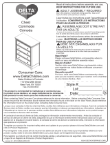
Step 9
Étape 9
Paso 9
1) Choose BOTTOM or TOP attachment.
2) Locate the through holes in the back of the dresser.
3) Align the hole to be used with the wood wall stud (For Open Bottom Installation, use wood wall stud closest to center)
1) Choisissez une fixation SUPÉRIEURE ou INFÉRIEURE.
2) Repérez les trous percés au dos de la commode.
3) Alignez le trou à utiliser sur le poteau mural en bois (Pour une installation à fond ouvert, utilisez le poteau mural le plus
près du milieu)
1) Seleccione el aditamento SUPERIOR o INFERIOR.
2) Ubique los orificios pasantes en la parte posterior del mueble.
3) Alinee el orificio que utilizará con el pilar de la pared (para una instalación con fondo abierto, utilice el pilar de madera
más cercano al centro)
6) Attach the Tip-over restraint strap (ZZ) to the
wall using (1) Long Screw (XX) and (1) washer
(TT) as shown. The screw MUST be installed into
a wood wall stud (See WARNINGS for additional
information).
6) Fixez la sangle du dispositif de
non-renversement (ZZ) au mur à l’aide de (1) vis
longue (XX) et de (1) rondelle (TT) tel qu’illustré.
La vis DOIT être serrez dans un poteau mural en
bois (Pour de plus amples informations, veuillez
vous référer aux AVERTISSEMENTS).
6) Fije la correa de retención contra volcamiento
(ZZ) a la pared utilizando (1) tornillo largo (XX) y
(1) arandela (TT), como se indica. El tornillo
DEBE instalarse en un pilar de madera (para
obtener más información consulte las
ADVERTENCIAS).
ADVERTENCIA
El uso de herramientas de contención
de vuelcos tan solo puede reducir, pero
no eliminar, el riesgo de vuelco.
No intente atornillar a paredes hechas
únicamente de paneles. Debe
atornillar en un pilar u otra estructura
de madera similar, como un zócalo
fijado de manera segura. Si su pared no
tiene vigas de Madera, visite su ferretería o
tienda del ramo más cercana para conseguir un
sistema de anclaje que soporte una fuerza de
tiraje de hasta 50 LBS (22,7 Kgs) para su tipo de
muro. Si no está seguro sobre cómo encontrar
la viga de madera o tiene dudas sobre el tipo de
muro, contacte a un contratista profesional.
5) Drill Ø1/8” hole at Pencil Mark, in
wood wall stud
5) Percez un trou de 1/8 po de
diamètre à l’emplacement de la
marque au crayon, dans le poteau
mural en bois
5) Perfore un orificio de Ø1/8” en la
marca del lápiz, sobre el pilar de
madera
Wood Wall Stud
Poteau mural en bois
Pilar de madera
Pencil Mark
Marque faite au crayon
Marca de lápiz
XX
TT
ZZ
Tipover Restraint
Dispositif de non-renversement
Protección contra volcamiento
WARNING
Use of tip-over restraints may only
reduce, but not eliminate, the risk
of tip-over.
Do not attempt to screw into the
wallboard only. You must screw
into a wood wall stud or other
wood structure such as securely
attached baseboard. If your wall is
not wood stud construction, see your local
hardware store or home center for a wall
anchor system that will hold a pull force of
50 LBS in your wall type. If you are
unsure of how to locate the wood stud, or
of what type of wall you have, contact a
professional contractor.
AVERTISSEMENT
L’utilisation de dispositif anti-renversement
peut uniquement réduire les risques de
renversement, mais ne les élimine pas
totalement.
Ne tentez pas de le visser dans le panneau
de revêtement uniquement. Vous devez
visser dans un poteau mural en bois ou
toute autre structure en bois telle qu’une
plinthe solidement fixée. Si votre mur n'est pas
construit de montants de bois, voyez votre
quincaillerie locale ou centre de rénovation pour une
ancre de mur pouvant supporter 50 livres dans votre
type de mur. Si vous êtes incertain par rapport à
comment localiser le montant ou à quel type de mur
vous avez, contactez un entrepreneur professionnel.
4) Make a pencil mark on the wall using the wood rail as a
guide, pencil mark must be over wood wall stud. Then move
the case away from the wall.
4) Faites une marque sur le mur à l’aide d’un crayon en vous
servant du barre en bois comme guide, la marque au crayon
doit être au-dessus du poteau mural en bois. Ensuite,
déplacez la caisse afin de l’éloigner du mur.
4) Utilizando un lápiz, haga una marca en la pared utilizando
el barra de madera como guía; la marca debe estar sobre el
pilar de madera. Luego, aleje la carcasa de la pared.
/