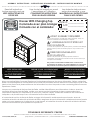
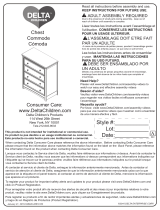
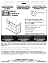
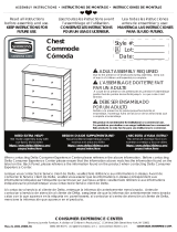
Delta Children Paloma 4 Drawer Dresser Assembly Instructions
- Taper
- Assembly Instructions

Read all instructions
before assembly and use.
KEEP INSTRUCTIONS FOR
FUTURE USE.
Lisez toutes les instructions avant
l’assemblage et l’utilisation.
CONSERVEZ LES INSTRUCTIONS
POUR UN USAGE ULTERIEUR.
Lea todas las instrucciones
antes de ensamblar y usar.
MANTENGA LAS INSTRUCCIONES
PARA SU USO FUTURO.
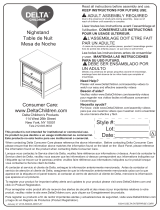
When contacting Delta Consumer Experience Center please reference the above information. Before contacting
Delta Consumer Experience Center please ensure that the information above matches the information found on the
label on the Back Panel, please reference the information found on the product when contacting Delta Consumer
Experience Center.
Lorsque vous contactez le Service client de Delta, veuillez faire référence aux informations ci-dessus. Avant de
contacter le Service client de Delta, veuillez vous assurer que les informations ci-dessus correspondent aux
informations indiquées sur l’étiquette qui se trouve sur panneau arrière; veuillez faire référence aux informations
indiquées sur le produit lorsque vous contactez le Service client de Delta.
Al contactar al servicio al cliente de Delta, entregue la información anteriormente mencionada. Antes de
contactar al servicio de atención al cliente de Delta, asegúrese de que la información anteriormente mencionada
calza con la que aparece en la etiqueta en panel trasero; al contactar al centro de atención al cliente de Delta,
mencione la información que aparece en el producto.
CONSUMER EXPERIENCE CENTER
Simmons Juvenile Furniture, A division of Children’s Products LLC |114 West 26th Street New York, NY 10001
(646) 435-8727 | [email protected] | www.DeltaChildren.com
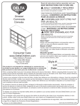
Style #:
Lot:
Date:
___________
___________
___________
C
REV
This product is not intended for institutional or commercial use.
Ce produit ne pas destine a un usage institutionnel ou commercial.
Este producto no esta hecho para uso institucional o comercial.
ADULT ASSEMBLY REQUIRED
Due to the presence of small parts during assembly, keep out
of reach of children until assembly is complete.
L’ASSEMBLAGE DOIT ETRE FAIT
PAR UN ADULTE
A cause de la presence de petites pieces, pendant l’assemblage
gardez hors de portee des enfants jusqu'a ce que celui-ci soit
termine.
DEBE SER ENSAMBLADO
POR UN ADULTO
Debido a la presencia de piezas pequeñas durante el
ensamblaje, mantenga fuera del alcance de los niños hasta que
complete el ensamblaje.
NEED EXTRA HELP?
We make assembly easy with
our tips & tricks video
https://www.deltachildren.com/
pages/instructions
BESOIN D'AIDE SUPPLÉMENTAIRE?
Nous facilitons l'assemblage avec
nos trucs et astuces vidéo
https://www.deltachildren.com/
pages/instructions
¿NECESITA AYUDA EXTRA?
Hacemos el montaje fácil con
nuestros consejos y trucos video
https://www.deltachildren.com/
pages/instructions
June 23, 2020, 41055, R0
©2020 DELTA ENTERPRISE CORP.
ASSEMBLY INSTRUCTIONS • INSTRUCTIONS DE MONTAGE • INSTRUCCIONES DE MONTAJE
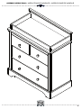
Dresser With Changing Top
Commode avec plan à langer
Cómoda con el cambiador
La page est en cours de chargement...
La page est en cours de chargement...

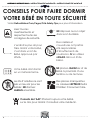
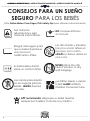
CONSEILS POUR FAIRE DORMIR
VOTRE BÉBÉ EN TOUTE SÉCURITÉ
Conseils de l’AAP: Placez toujours votre bébé
sur le dos pour dormir. Consultez votre médecin.
Visitez Deltachildren.Com/Pages/Crib-Safety-Tips pour plus d’information
NE déposez aucun objet
dans le Lit de Bébé
Votre bébé doit dormir
sur un matelas ferme.
Des oreillers et
couvertures ont parfois
été responsables
d’étouffements de
nourrissons. N’en utilisez
JAMAIS dans un lit de
bébé.
Les lits d’adultes ne sont
pas un lieu sûr pour les
bébés: NE dormez
JAMAIS ensemble.
NE placez JAMAIS le Lit de
Bébé à proximité d’une
fenêtre ou de tentures.
L’endroit le plus sûr pour
faire dormir votre bébé,
c’est dans un Lit de
Bébé approuvé par
JPMA.
Des pièces manquantes
ou cassées?APPELEZ Delta
Children Consumer Care.
Lisez tous les
avertissements et
respectez toutes les
consignes de sécurité.
ASSEMBLY INSTRUCTIONS • INSTRUCTIONS DE MONTAGE • INSTRUCCIONES DE MONTAJEASSEMBLY INSTRUCTIONS • INSTRUCTIONS DE MONTAGE • INSTRUCCIONES DE MONTAJEASSEMBLY INSTRUCTIONS • INSTRUCTIONS DE MONTAGE • INSTRUCCIONES DE MONTAJE
4

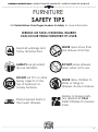
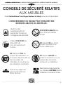
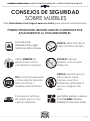
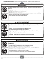
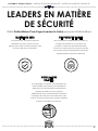
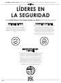
LE RENVERSEMENT DU MEUBLE PEUT ENTRAÎNER DES
BLESSURES GRAVES OU MORTELLES.
NE déposez PAS de
postes de télévision ou
d’autres objets lourds sur
des meubles de
chambre à coucher ou
de chambre d’enfants.
Utilisez TOUJOURS les
dispositifs de
non-renversement
fournis.
NE laissez JAMAIS les
enfants monter sur ou se
suspendre aux tiroirs,
portes et ou tablettes.
Placez les objets les
plus lourds dans les
tiroirs du bas.
N’OUVREZ JAMAIS plus
d’un tiroir en même
temps
NE laissez PAS les tiroirs
ouverts lorsque vous
ne les utilisez pas.
Visitez Deltachildren.Com/Pages/Leaders-In-Safety pour plus d’information
ASSEMBLY INSTRUCTIONS • INSTRUCTIONS DE MONTAGE • INSTRUCCIONES DE MONTAJEASSEMBLY INSTRUCTIONS • INSTRUCTIONS DE MONTAGE • INSTRUCCIONES DE MONTAJE
Lisez tous les
avertissements et
respectez toutes les
consignes de sécurité.
Des pièces manquantes
ou cassées?APPELEZ Delta
Children Consumer Care.
CONSEILS DE SÉCURITÉ RELATIFS
AUX MEUBLES
5
La page est en cours de chargement...
La page est en cours de chargement...
La page est en cours de chargement...

ASSEMBLY INSTRUCTIONS • INSTRUCTIONS DE MONTAGE • INSTRUCCIONES DE MONTAJEASSEMBLY INSTRUCTIONS • INSTRUCTIONS DE MONTAGE • INSTRUCCIONES DE MONTAJEASSEMBLY INSTRUCTIONS • INSTRUCTIONS DE MONTAGE • INSTRUCCIONES DE MONTAJE
DELTA CHILDREN
@deltachildren
SUIVEZ NOUS POUR AVOIR PLUS DE CHANCES DE GAGNER /
SÍGANOS PARA TENER MAS CHANCES DE GANAR
SCANNEZ ICI / ESCANEE AQUÍ
Pour plus d'informations et
pour voir tous nos produits
Para más información y para
ver todos nuestros productos
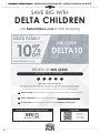
ÉCONOMISEZ BEAUCOUP AVEC
AHORRE MUCHO CON
Visitez Deltachilren.com Pour Commencer Vos Achats
Visita Deltachilren.com Para Comenzar A Comprar
FAMILLE DELTA
Bienvenue dans la
Voici Notre Cadeau Pour Vous
Votre Prochain Achat Chez
*Subject to Change
*Exclusions Apply
*Des exclusions s’appliquent
*Sujet à changement
Aquí Está Nuestro Regalo Para Usted
FAMILIA DELTA
Bienvenido a la
Su Próxima Compra En
DeltaChildren.com
DELTA10
UTILISEZ LE CODE:
UTILICE EL CÓDIGO:
ECRIVEZ UN COMMENTAIRE CLIENT pour ce produit sur le site web du magasin où il a été acheté
CALIFIQUE EL PRODUCTO en la página web de la tienda donde haya sido comprado
1
FAITES UNE CAPTURE D’ECRAN de votre commentaire client et mettez la en ligne sur www.DeltaChildren.com/Review
HAGA UNA CAPTURA DE PANTALLA de su calificación y cárguela a la pagina www.DeltaChildren.com/Review
2
C’EST AUSSI SIMPLE QUE ÇA! Dès que c’est fait vous serez instantanément INSCRIT POUR GAGNER 2500$
ES ASÍ DE FÁCIL! En cuanto lo envíe ya estará instantáneamente PARTICIPANDO PARA GANAR $2.500
3
REGLEMENT DE PARTICIPATION / REGLAS PARA PARTICIPAR
LAISSEZ UN COMMENTAIRE CLIENT POUR GAGNER $2500
CALIFIQUE EL PRODUCTO PARA GANAR $2500
9

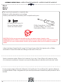
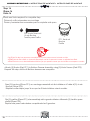
NOTES ON ASSEMBLY:
-During the assembly process whenever using screws or bolts, check each by placing the screw/bolt on the
diagram of the item which is drawn actual size and design. Be sure to use the proper size and shape specified
in the instructions.
-To assemble this unit you may be required to place the unit on it’s side and face. It is strongly recommended
that assembly is done on a soft, non-abrasive surface to avoid damaging the finish.
NOTES ON CARE AND MAINTENANCE:
- Do not scratch or chip the finish.
- Inspect the product periodically, contact Delta Children's Products for replacement parts or questions.
- Do not store the product or any parts in extreme temperatures and conditions such as a hot attic or a damp,
cold basement. These extremes can cause a loss of structural integrity.
-To preserve the luster of the high quality finish on your product, it is recommended to place a doily or felt
pad under any items you place on the finish.
-Clean with a damp cloth, then a dry cloth to preserve the original luster and beauty of this fine finish.
-Do not use abrasive chemicals.
-Do not spray cleaners directly onto furniture.
-Lift slightly when moving on carpeting to prevent leg breakage.
-Use of a vaporizer near furniture will cause wood to swell and finish to peel.
REMARQUES SUR L’ASSEMBLAGE :
-Lors de l’assemblage, quand vous utilisez vis ou boulons, verifiez chaque piece en placant le vis/boulon sur le
diagramme de la piece concernee qui est dessine en taille et forme reelle. Assurez vous d’utiliser
la taille et la forme exacte comme il est specifie dans les instructions.
-Pour assembler cet element vous pourriez avoir besoin de le placer sur le cote lateral et sur le cote frontal. Il
est fortement recommandé de faire l’assemblage sur une surface lisse, non abrasive (comme
le film mousse de l'emballage)pour eviter d’endommager les finitions.
REMARQUES SUR LE SOIN ET L’ENTRETIEN:
-Ne pas rayer ou ebrecher la finition.
-Examinez de pres le produit regulierement, contactez Delta Children’s Products pour les pieces de rechange
ou pour poser des questions.
-Ne pas ranger le produit ou des pieces a des temperatures extremes ou dans des conditions comme un
grenier chaud ou une cave froide et humide. Ces extremes peuvent causer une perte de l’integrite de la
structure du produit
-Pour préserver le lustre original et la beauté de ce fini raffiné nettoyer avec un chiffon humide, puis un
chiffon sec.
-Ne pas utiliser des produits chimiques abrasifs
-Ne pas pulveriser un nettoyant directement sur le meuble, pulveriser sur le torchon et puis appliquer sur le
meuble. Testez le produit nettoyant sur un endroit discret avant de l’utiliser sur la totalite du meuble
-Lors d’un deplacement sur une moquette ou tapis, soulevez legerement le meuble pour eviter de casser les
pieds.
-L’utilisation d’un vaporisateur pres du meuble causera le gonflement du bois et l’ecaillage de la finition.
INFORMACIÓN SOBRE EL MONTAJE:
-Durante el proceso de montaje, ya utilice pernos o tornillos, compruebe cada uno de ellos colocando el
perno/tornillo en el diagrama del artículo donde está dibujado el tamaño y el diseño real. Asegúrese de que
utiliza el tamaño y la forma adecuada que especifican las instrucciones.
-Para montar esta unidad, puede que se le solicite que coloque la unidad de lado y de cara. Se recomien-
da encarecidamente que realice el montaje sobre una superficie no abrasiva (Como la envoltura de emba-
laje de espuma) para evitar dañar el acabado.
NOTAS SOBRE SU CUIDADO Y MANTENIMIENTO:
- No arañe ni desconche el acabado.
- Inspeccione el producto con regularidad, póngase en contacto con Delta Children’s Products para el
recambio de partes o para formular preguntas.
- No guarde el producto ni ninguna de sus partes a temperaturas ni en condiciones extremas como un ático
caluroso o un sótano húmedo y frío. Estos extremos pueden provocar una pérdida de integridad estructural.
-Para preservar el brillo del acabado de alta calidad que recubre su producto, se recomienda que coloque
un paño o una almohadilla de fieltro debajo de cualquier objeto que coloque sobre el acabado.
-Límpielo con un trapo húmedo y luego con uno seco para preservar el brillo y la belleza originales de este
fino acabado.
-No utilice productos químicos abrasivos.
-No pulverice limpiadores directamente sobre el mueble.
-Elévelo ligeramente cuando lo mueva sobre alfombras o moqueta para evitar que se rompan las patas.
-El uso de vaporizadores cerca de muebles puede provocar que la madera se hinche y acabe
desconchándose.
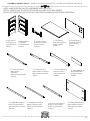
10

A. Left Side x1
Côté gauche
Lado izquierdo
#41046
B. Right Side x1
Côté droit
Lado derecho
#41047
D. Center Panel
Panneau central
Panel central
#41048
C. Top Panel
Panneausupérieur
Panel superior
#26413
K. Back Panel x1
Panneau arrière
Panel trasero
#26420
E. Top Front Rail x1
Barre avant
supérieur
Barra frontal superior
#26414
G. Middle Front Rail x1
Barre Central Avant
Barra Frontal Central
#26415
N. Bottom Front Rail x1
Barre avant inférieur
Barra frontal inferior
#26416
F. Top Back Rail x1
Barre arrière supérieur
Barra trasero superior
#26417
H. Middle Back Rail x1
Barre Central Arrière
Barra Posterior Central
#26418
P. Bottom Back Rail x1
Barre arrière inférieur
Barra trasero inferior
#26419
L. Front Molding x1
Moulure avant
Moldura frontal
#26804
M. Side Molding x2
Moulurelatérale
Moldura lateral
#26805
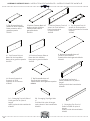
11
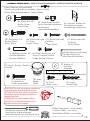
PARTS: MAKE SURE THAT ALL PRE-ASSEMBLED PARTS ARE TIGHT
PIÈCES : VÉRIFIEZ QUE TOUTES LES PIÈCES PRÉ-MONTÉES SONT BIEN SERRÉES.
PIEZAS: ASEGÚRESE DE QUE TODAS LAS PIEZAS PRE-ENSAMBLADAS ESTÁN BIEN APRETADAS.
ASSEMBLY INSTRUCTIONS • INSTRUCTIONS DE MONTAGE • INSTRUCCIONES DE MONTAJE

V1. Top Drawer Side x4
Barre de tiroir supérieur
Barra de la gaveta superior
#41050
W. Drawer Support x4
Support du Tiroir
Soporte de la Gaveta
#26429
#26424
U. Top Drawer Front x2
Avant du Tiroirsupérieur
Parte frontal de la Gaveta
superior
#41049
T. Bottom Drawer Front x2
Avant du Tiroir inférieur
Parte frontal de la
Gaveta inferior
#41052
R. Top Drawer Back x2
Arrière du tiroir supérieur
Parte posterior de la
gaveta superior
#41051
Z. Top Drawer Bottom x2
Fond du tiroir supérieur
Parte inferior de la gaveta superior
S. Bottom Drawer Back x2
Arrière du tiroir inférieur
Parte posterior de la
gaveta inferior
#41054
X. Bottom Drawer Bottom x2
Fond du tiroir inférieur
Parte inferior de la gaveta inferior
#26428
V2. Bottom Drawer Side x4
Barre de tiroir inférieur
Barra de la gaveta inferior
#41053
J. Changing Top Back x1
Partie postérieure du plan à
langer
Parte posterior del cambiador
#26430
Y. Changing Top Front x1
Partie frontale du plan à
langer
Parte frontal del cambiador
#26431
Q1. Changing Top Left Side x1
Coté gauche du plan à
langer
Lado izquierdo del cambiador
#26432
Q2. Changing Top Right side
x1
Coté droit du plan à langer
Lado derecho del cambiador
#26433
12
ASSEMBLY INSTRUCTIONS • INSTRUCTIONS DE MONTAGE • INSTRUCCIONES DE MONTAJE

Parts: Hardware kits part#26434
Pièces: L'ensemble de quincaillerie - pièce n°26434
Piezas: El kit de herramientas - Pieza #26434
HH. Back Panel Screw x14
Vis pour Panneau Arrière
Tornillo de Panel Trasero
JJ. Φ6x30mm Dowel x41
Cheville Φ6x30mm
Pasador Φ6x30mm
PP. Knob / Bouton / Perilla x6
#26436
PP1. Knob
Bouton
Perilla
PP2. Knob Screw
Vis de Bouton
Tornillo para Perilla
DD. 30mm Bolt x14
Boulon 30mm
Perno 30mm
KK. Crescent Washer x10
Rondelle en croissant
Arandela de media luna
BB. 55mm Bolt x20
Boulon 55mm
Perno 55mm
EE. Plastic Barrel Nut x20
Écrou à portée cylindrique
en plastique
Tuercacilíndricaplástica
GG. 25mm Screw x40
Vis 25mm
Tornillo 25mm
NN.12mm Screw x24
Vis 12mm
Tornillo 12mm
FF. 40mm Screw x20
Vis 40mm
Tornillo 40mm
M4 Allen Wrench (included)
Clé Allen M4 (inclus)
Llave Allen M4 (incluido)
Phillips Screwdriver – Not included
Tournevis Phillips - non inclus
Destornillidor Phillips – no incluido
M4 Ballend Screwdriver
tournevis M4 à tête sphérique
destornillador M4 con cabeza de bola
CAUTION: Do Not use a power screwdriver
they can cause screws to break or strip.
ATTENTION: Ne Pas utiliser un tournevis
électrique car les vis peuvent casser ou
perdre leurs filets.
ATENCIÓN: No use un destornillador
eléctrico ya que puede causar que los
tornillos se rompan o rueden.
11
YY. Short Screw x1
Vis Court
Tornillo corto
XX. Long Screw x1
Vis Longue
Tornillo Largo
TT. Washer x2
Rondelle
Arandela
ZZ. (1) Wall Strap/Sangle murale/Abrazadera
13
ASSEMBLY INSTRUCTIONS • INSTRUCTIONS DE MONTAGE • INSTRUCCIONES DE MONTAJEASSEMBLY INSTRUCTIONS • INSTRUCTIONS DE MONTAGE • INSTRUCCIONES DE MONTAJE

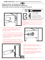
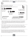
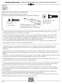
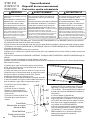
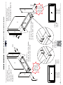
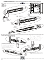
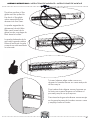
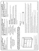
1. Insert the Dowels in the Rail into the holes in
the Post.
1. Insérer les chevilles dans le rail dans les orifices
dans le poteau.
1. Inserte los pasadores del Riel en los agujeros
del Poste.
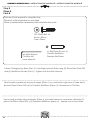
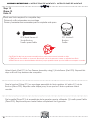
2. Insert the Bolt into the slot. Turn clockwise
with fingers or the Ball End Screwdriver
provided. DO NOT fully tighten, leave 1/2”
(12mm) exposed.
2. Insérez le boulon dans la fente. Tournez dans
le sens des aiguilles d’une montre à l’aide des
doigts ou de la tournevis à tête sphérique. Ne
Pas serrer complètement et laisser 12 mm (1/2
pouces) exposés.
2. Inserte el perno en la ranura. Gírelo en el
sentido de las agujas del reloj con los dedos o
con el destornillador con cabeza de bola. NO
lo apriete del todo, deje 1/2" (12 mm) fuera.
3. Slide the Crescent Washer over the
exposed bolt, behind the head of the bolt.
3. Glissez la rondelle en croissant sur l'écrou
exposé, derrière la tête de l'écrou.
3. Abrace la parte del Perno que quedó
fuera, debajo de la cabeza del mismo, con
la Arandela de media luna.
Hardware System - Review Before Assembly
Quincaillerie – Lire Avant D’effectuer Le Montage
Revise Antes De Armar- Elementos De Fijacion Y Ensamble
KK. Crescent Washer
Rondelle en Croissant
Arandela de Media Luna
BB. 55mm Bolt
Boulon 55mm
Perno 55mm
14
ASSEMBLY INSTRUCTIONS • INSTRUCTIONS DE MONTAGE • INSTRUCCIONES DE MONTAJEASSEMBLY INSTRUCTIONS • INSTRUCTIONS DE MONTAGE • INSTRUCCIONES DE MONTAJE

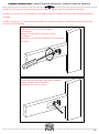
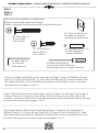
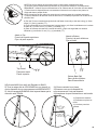
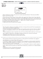
Install (1) bolt and (1) crescent washer at a time. Tighten until it looks like the picture.
Installez (1) boulon et (1) rondelle en croissant à la fois. Serrez jusqu'à ce que cela ressemble à
l'image.
Instale (1) perno y (1) Arandela de media luna al mismo tiempo. Apriételos hasta que quede
como en la ilustración.
Ensure all bolts are tight with Allen wrench.
Serrez à l’aide de la clé Allen.
Apriételo con la llave Allen.
Tighten the bolt with the ball end
screwdriver.
Serrez à l’aide de la Tournevis à tête
sphérique.
Apriételo con el Destornillador hcon cabeza
de bola.
15
ASSEMBLY INSTRUCTIONS • INSTRUCTIONS DE MONTAGE • INSTRUCCIONES DE MONTAJEASSEMBLY INSTRUCTIONS • INSTRUCTIONS DE MONTAGE • INSTRUCCIONES DE MONTAJE

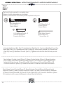
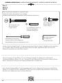
JJ. Φ6x30mm Dowel x3
Cheville Φ6x30mm
Pasador Φ6x30mm
DD. 30mm Bolt x2
Boulon 30mm
Perno 30mm
BB. 55mm Bolt x2
Boulon 55mm
Perno 55mm
M4 Allen Wrench
Clé Allen M4
Llave Allen M4
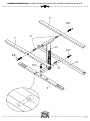
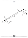
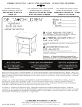
Attach Middle Front Rail (Part G), Middle Back Rail (Part H), Top Front Rail (Part E) and Top
Back Rail (Part F) to Center panel (Part D) using (2) 55mm bolts (Part BB), (2) 30mm bolts
(Part DD) and (3) Φ6x30mm Dowels (Part JJ). Tighten bolts with M4 Allen wrench provid-
ed.
Fije la Barra Frontal Central (Pieza G), Barra Posterior Central (Pieza H), Barra Frontal
Superior (Pieza E) y Barra Posterior Superior (Pieza F) al Panel Central (Pieza D) utilizando
(2) Pernos 55mm (Pieza BB), (2) Pernos 30 mm (Pieza DD) y (3) Pasadors Φ6x30mm (Pieza
JJ). Apriete todos los pernos utilizando la llave Allen M4 incluida.
Fixer le Barre Central Avant (Pièce G), Barre Central Arrière (Pièce H), Barre Supérieur
avant (Pièce E) et Barre Supérieur Arrière (Pièce F) aux Panneau Central (Pièce D) à
l’aide de (2) boulons de 55 mm (Pièce BB), (2) boulons de 30 mm (Pièce DD) et (3)
Chevilles Φ6x30mm (Pièce JJ). Serrer les boulons à l’aide de la clé Allen M4 fournie.
Step 1
Étape 1
Paso 1
Parts and tools required to complete step
Pièces et outils nécessaires au montage
Piezas y herramientas necesarias para completar este paso
16
ASSEMBLY INSTRUCTIONS • INSTRUCTIONS DE MONTAGE • INSTRUCCIONES DE MONTAJEASSEMBLY INSTRUCTIONS • INSTRUCTIONS DE MONTAGE • INSTRUCCIONES DE MONTAJE
La page est en cours de chargement...

DD. 30mm Bolt x1
Boulon 30mm
Perno 30mm
JJ. Φ6x30mm Dowel x10
Cheville Φ6x30mm
Pasador Φ6x30mm
BB. 55mm Bolt x5
Boulon 55mm
Perno 55mm
KK. Crescent Washer x5
Rondelle en croissant
Arandela de media luna
M4 Ballend Screwdriver
tournevis M4 à tête sphérique
destornillador M4 con cabeza de bola
M4 Allen Wrench
Clé Allen M4
Llave Allen M4
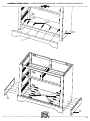
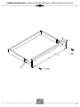
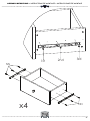
Attach the assembly from Step 1 and Bottom Front Rail (Part N) and Bottom Back Rail
(Part P) to the Left Side (Part A) using (10) Φ6x30mm Dowels (Part JJ), (1) 30mm Bolt
(Part DD), (5) 55mm Bolts (Part BB) and (5) Crescent Washers (Part KK). Tighten the Bolts
with the M4 Ballend Screwdriver and M4 Allen wrench, following the instructions on
pages 14 and 15.
Fixer le l’ensemble monté à l’étape 1, Barre Avant Inférieur (Pièce N) et Barre arrière
inférieur (Pièce P) au côté gauche (Pièce A) à l’aide de (10) Chevilles Φ6x30mm (Pièce
JJ), (1) boulon 30 mm (Pièce DD), (5) boulons 55 mm (Pièce BB), et (5) rondelles « croissant
» (Pièce KK) à l’aide de dutournevis M4 à tête sphériqueet la clé Allen M4 ensuivant les
instructions pages 14 et 15.
Fije el ensamblaje del Paso 1, Barra Frontal Inferior (Parte N) y la Barra trasero inferior
(Parte P) al Lado Izquierdo (Parte A) utilizando (10) Pasadores Φ6x30mm (Pieza JJ), (1)
Perno 30 mm (Pieza DD), (5) Pernos 55 mm (Pieza BB) y (5) Arandelas de Media Luna
(Pieza KK) utilizando el destornillador M4 con cabeza de bola y la llave Allen M4 siguien-
do las instrucciones de laspáginas 124 y 15.
Step 2
Étape 2
Paso 2
Parts and tools required to complete step
Pièces et outils nécessaires au montage
Piezas y herramientas necesarias para completar este paso
18
ASSEMBLY INSTRUCTIONS • INSTRUCTIONS DE MONTAGE • INSTRUCCIONES DE MONTAJEASSEMBLY INSTRUCTIONS • INSTRUCTIONS DE MONTAGE • INSTRUCCIONES DE MONTAJE
La page est en cours de chargement...

DD. 30mm Bolt x1
Boulon 30mm
Perno 30mm
JJ. Φ6x30mm Dowel x10
Cheville Φ6x30mm
Pasador Φ6x30mm
KK. Crescent Washer x5
Rondelle en croissant
Arandela de media luna
BB. 55mm Bolt x5
Boulon 55mm
Perno 55mm
M4 Ballend Screwdriver
tournevis M4 à tête sphérique
destornillador M4 con cabeza de bola
M4 Allen Wrench
Clé Allen M4
Llave Allen M4
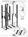
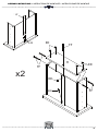
Attach the Right Side (Part B) to the assembly from Step 2 using (10) Φ6x30mm Dowels
(Part JJ), (1) 30mm Bolt (Part DD), (5) 55mm Bolt (Part BB) and (5) Crescent Washer (Part
KK). Tighten the Bolts with the M4 Ballend Screwdriver and M4 Allen wrench, following
the instructions on pages 14 and 15.
Fixer le Côté droit (Pièce B) au l’ensemble monté à l’étape 2 à l’aide de (10) Chevilles Φ
6x30mm (Pièce JJ), (1) boulon 30 mm (Pièce DD), (5) boulons 55 mm (Pièce BB), et (5)
rondelles « croissant » (Pièce KK) à l’aide de dutournevis M4 à tête sphériqueet la clé Allen
M4 ensuivant les instructions pages 14 et 15.
Fije el Lado derecho (Pieza B) al ensamblaje del Paso 2 utilizando (10) Pasadores Φ
6x30mm (Pieza JJ), (1) Perno 30 mm (Pieza DD), (5) Pernos 55 mm (Pieza BB) y (5) Aran-
delas de Media Luna (Pieza KK) utilizando el destornillador M4 con cabeza de bola y la
llave Allen M4 siguiendo las instrucciones de laspáginas 14 y 15.
Step 3
Étape 3
Paso 3
Parts and tools required to complete step
Pièces et outils nécessaires au montage
Piezas y herramientas necesarias para completar este paso
20
ASSEMBLY INSTRUCTIONS • INSTRUCTIONS DE MONTAGE • INSTRUCCIONES DE MONTAJEASSEMBLY INSTRUCTIONS • INSTRUCTIONS DE MONTAGE • INSTRUCCIONES DE MONTAJE
La page est en cours de chargement...

GG. 25mm Screw x17
Vis 25mm
Tornillo 25mm
Phillips Screwdriver – Not included
Tournevis Phillips - non inclus
Destornillidor Phillips – no incluido
DD. 30mm Bolt x2
Boulon 30mm
Perno 30mm
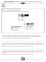
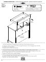
1-Loosely attach Front Molding (Part L) using (2) 30mm Bolts (Part DD), align the top of the
molding with the top of the Bottom Front Rail.
2- Attach the side moldings (part M) to each side using (12) 25mm Screws (Part GG). Align
the front of the Side Molding with the Front Molding. Tighten with a Phillips Screw Driver.
3- Check that the Front Molding is centered by verifying the alignment on each side. Note,
the front molding will be slightly past the side molding on both sides.
4 - Secure the Front Molding with (5) 25mm Screws (Part GG), tighten with a Phillips Screw-
driver. Tighten the bolts with the M4 Allen Wrench.
1- Fijar holgadamente la moldura frontal (pieza L) utilizando (2) pernos de 30mm (pieza DD),
alinear la parte superior de la moldura con la parte superior del riel frontal inferior.
2. Fijar las molduras laterales (pieza M) a cada lado utilizando (12) tornillos de 25mm (pieza
GG). Alinear el frente de la moldura lateral con la moldura frontal. Apretar con el destornilla-
dor de estrella.
3- Revisar que la moldura frontal esté centrada verificando el alineamiento en cada lado.
Nota, la moldura frontal estará ligeramente pasada en ambos lados.
4. Asegurar la moldura frontal con (5) tornillos de 25mm (pieza GG), apretar con el destornil-
lador de estrella. Apretar los pernos con la llave Allen M4.
1- Fixez sans serrer la moulure frontale (pièce L) à l’aide de (2) boulons 30mm (pièce DD),
alignez la partie supérieure de la moulure avec la partie supérieure de la barre frontale
inférieure.
2- Fixez les moulures latérales (pièce M) à chaque côté à l’aide de (12) vis 25mm (pièce GG).
Alignez le devant de la moulure latérale avec la moulure frontale. Serrez avec un tournevis
Phillips.
3- Assurez vous que la moulure frontale soit centrée, en vérifiant l’alignement de chaque côté.
Remarque, la moulure frontale dépassera légèrement de chaque côté.
4- Fixez proprement la moulure frontale à l’aide de (5) 25mm vis (pièce GG), serrez avec un
tournevis Phillips. Serrez les boulons avec la clé Allen M4.
Step 4
Étape 4
Paso 4
Parts and tools required to complete step
Pièces et outils nécessaires au montage
Piezas y herramientas necesarias para completar este paso
22
ASSEMBLY INSTRUCTIONS • INSTRUCTIONS DE MONTAGE • INSTRUCCIONES DE MONTAJEASSEMBLY INSTRUCTIONS • INSTRUCTIONS DE MONTAGE • INSTRUCCIONES DE MONTAJE
La page est en cours de chargement...

JJ. Φ6x30mm Dowel x2
Cheville Φ6x30mm
Pasador Φ6x30mm
BB. 55mm Bolt x8
Boulon 55mm
Perno 55mm
DD. 30mm Bolt x4
Boulon 30mm
Perno 30mm
M4 Ballend Screwdriver
tournevis M4 à tête sphérique
destornillador M4 con cabeza de bola
M4 Allen Wrench
Clé Allen M4
Llave Allen M4
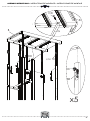
Attach the Top Panel (Part C) to the assembly from Step 4 using (2) Φ6x30mm Dowels (Part
JJ), (4) 30mm Bolts (Part DD) and (8) 55mm Bolts (Part BB). Tighten the Bolts with the M4
Ballend Screwdriver and M4 Allen wrench.
Fixer le Panneau Avant (Pièce C) au montage assemblé à l’étape 4 à l’aide de (2)
Chevilles Φ6x30mm (Pièce JJ), (4) Boulons 30 mm (Pièce DD) et (8) Boulons 55mm (Pièce
BB) à l’aide de du tournevis M4 à tête sphériqueet la cléAllen M4.
Fije el Panel Superior(Pieza C) al ensamblaje del Paso 4 utilizando (2) Pasadores Φ6x30mm
(Pieza JJ), (4) Pernos 30 mm (Pieza DD) y (8) Pernos 55 mm(Pieza BB) utilizando el destornilla-
dor M4 con cabeza de bola y la llave Allen M4.
Step 5
Étape 5
Paso 5
Parts and tools required to complete step
Pièces et outils nécessaires au montage
Piezas y herramientas necesarias para completar este paso
24
ASSEMBLY INSTRUCTIONS • INSTRUCTIONS DE MONTAGE • INSTRUCCIONES DE MONTAJEASSEMBLY INSTRUCTIONS • INSTRUCTIONS DE MONTAGE • INSTRUCCIONES DE MONTAJE
La page est en cours de chargement...

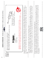
CAUTION: Do Not use a power screwdriver they can cause screws to break or strip.
ATTENTION: Ne Pas utiliser un tournevis électrique car les vis peuvent casser ou perdre leurs filets.
ATENCIÓN: No use un destornillador eléctrico ya que puede causar que los tornillos se rompan o
rueden.
HH. Back Panel Screw x14
Vis pour Panneau Arrière
Tornillo de Panel Trasero
Phillips Screwdriver – Not included
Tournevis Phillips - non inclus
Destornillidor Phillips – no incluido
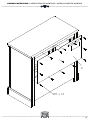
Attach the Back Panel (Part K) using (14) 15mm Screws (Part HH), tighten with a Phillips
screwdriver. Ensure the labels are facing to the back of the unit.
Fixez le panneau arrière (Pièce K) à l’aide de (14) vis de 15 mm (Pièce HH), serrez à l’aide
d’un tournevis cruciforme. Assurez-vous que les étiquettes est orientée vers le dos de l’unité.
Una el panel posterior (Pieza K) utilizando (14) tornillos de 15 mm (Pieza HH), apriete utilizando
un destornillador Philips. Asegúrese de que las etiquetas estan enfrente la parte posterior de la
unidad.
Step 6
Étape 6
Paso 6
Parts and tools required to complete step
Pièces et outils nécessaires au montage
Piezas y herramientas necesarias para completar este paso
26
ASSEMBLY INSTRUCTIONS • INSTRUCTIONS DE MONTAGE • INSTRUCCIONES DE MONTAJEASSEMBLY INSTRUCTIONS • INSTRUCTIONS DE MONTAGE • INSTRUCCIONES DE MONTAJE
La page est en cours de chargement...

JJ. Φ6x30mm Dowel x4
Cheville Φ6x30mm
Pasador Φ6x30mm
DD. 30mm Bolt x2
Boulon 30mm
Perno 30mm
M4 Allen Wrench
Clé Allen M4
Llave Allen M4
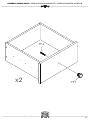
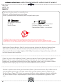
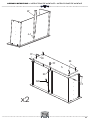
1. Attach Changing Top Right Side (Part Q2) to the Changing Top Front (Part Y) using (1)
30mm Bolt (Part DD) and (2) Φ6x30mm Dowels (Part JJ). Tighten with the Allen Wrench.
2. Attach Changing Top Left Side (Part Q1) in the same manner
1. Fixer le coté droit du plan à langer (Pièce Q2) à la partie frontale du plan à langer (Pièce Y)
à l’aide de (1) Boulon 30mm (Pièce DD) et (2) Chevilles Φ6x30mm (Pièce JJ). Serrezavec la Clé
Allen.
2. Fixer le coté gauche du plan à langer (Pièce Q1) de la même façon.
1. Fijar el lado derecho del cambiador (pieza Q2) con la parte frontal del cambiador (pieza Y)
utilizando (1) perno de 30mm (pieza DD) y (2) Pasadors Φ6x30mm (pieza JJ). Apriete con la
Llave Allen.
2. Fijar el lado izquierdo del cambiador (pieza Q1) de la misma manera.
Step 7
Étape 7
Paso 7
Parts and tools required to complete step
Pièces et outils nécessaires au montage
Piezas y herramientas necesarias para completar este paso
28
ASSEMBLY INSTRUCTIONS • INSTRUCTIONS DE MONTAGE • INSTRUCCIONES DE MONTAJEASSEMBLY INSTRUCTIONS • INSTRUCTIONS DE MONTAGE • INSTRUCCIONES DE MONTAJE
La page est en cours de chargement...

JJ. Φ6x30mm Dowel x4
Cheville Φ6x30mm
Pasador Φ6x30mm
DD. 30mm Bolt x2
Boulon 30mm
Perno 30mm
M4 Allen Wrench
Clé Allen M4
Llave Allen M4
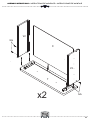
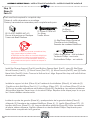
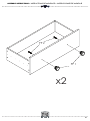
Attach Changing Top Back (Part J) to the Right and Left Sides using (2) 30mm Bolts (Part DD)
and (4) Φ6x30mm Dowels (Part JJ) . Tighten with the Allen Wrench.
Fixer la partie postérieure du plan à langer (Pièce J) au cotés droit et gauche à l’aide de (2)
Boulons 30mm (Pièce DD) et (4) Chevilles Φ6x30mm (Pièce JJ). Serrezavec la Clé Allen.
Fijar la parte posterior del cambiador (Pieza J) a los lados derecho e izquierdo utilizando (2)
pernos de 30mm (Pieza DD) y (4) Pasadors Φ6x30mm (pieza JJ). Apriete con la Llave Allen.
Step 8
Étape 8
Paso 8
Parts and tools required to complete step
Pièces et outils nécessaires au montage
Piezas y herramientas necesarias para completar este paso
30
ASSEMBLY INSTRUCTIONS • INSTRUCTIONS DE MONTAGE • INSTRUCCIONES DE MONTAJEASSEMBLY INSTRUCTIONS • INSTRUCTIONS DE MONTAGE • INSTRUCCIONES DE MONTAJE
La page est en cours de chargement...

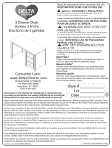
GG. 25mm SCREW x3
Vis 25mm
Tornillo 25mm
Phillips Screwdriver – Not included
Tournevis Phillips - non inclus
Destornillidor Phillips – no incluido
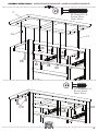
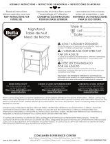
1. Set the Assembled Changing Top on the top of the Dresser as shown.
2. Insert
(3)
25 mm screws (Part GG) through the back of the Changing Top, into the
pre drilled holes the dresser.
3. Tighten with a Phillips Screwdriver.
1. Placer la Table à Langer maintenant assemblée sur ledessusde la commode.
2. Insérer (3) vis 25mm (pièce GG) à partir del’arrière de la table à langer, jusque dans
les trous deguidage que l’onvientde percer dans la commode.
3. Serrer au moyen d’un tournevis phillips.
1. Poner el equipó de ensemblaje ensima del cambiador.
2.Inserta (3) tornillos 25 mm (pieza GG) en laparte de atras en los wecos pil
ót.
3.Apriete con destornillador phillips.
DRESSER UNIT
LA COMMODE
LA COMMODA
GG
GG
GG
Step 9
Étape 9
Paso 9
32
ASSEMBLY INSTRUCTIONS • INSTRUCTIONS DE MONTAGE • INSTRUCCIONES DE MONTAJEASSEMBLY INSTRUCTIONS • INSTRUCTIONS DE MONTAGE • INSTRUCCIONES DE MONTAJE

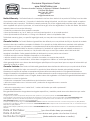
WARNING
FALL HAZARD - To prevent death or serious injury, always keep child within arm’s reach.
Read all instructions before use of the changing top.
KEEP THESE INSTRUCTIONS IN A SAFE PLACE FOR FUTURE USE.
Inspect the changing table periodically. Do not use the changing top if it is damaged or broken.
Contact Simmons Juvenile Furniture with any questions.
Tighten all loose screws and bolts before each use.
The maximum recommended weight of the child is 30lbs for the changing table.
Always secure the changing top to the changing surface using the screws provided. See Instructions.
Secure the changing top only to Simmons Juvenile Furniture item 328040.
The changing pad used should be 34" x 16" with a maximum thickness of 1".
RISQUE DE CHUTE – Afin de prévenir tout risque de décès ou de blessure grave, toujours demeurer à
portée de bras de l’enfant placé sur la table à langer.
Bien lire toutes les instructions avant d’utiliser la table à langer
CONSERVER CES INSTRUCTIONS DANS UN ENDROIT SÛR POUR RÉFÉRENCE ULTÉRIEURE.
Inspecter régulièrement la table à langer. Ne pas l’utiliser si elle est endommagée ou brisée. Si vous
avez des questions contactez Simmons Juvenile Furniture.
Serrer tous les boulons et vis desserrés avant chaque usage.
Le poids maximum recommandé est de 30 livres (13,6kg).
Toujours fixer la table à langer à la surface de la table à langer en utilisant les vis fournies. Consulter
les directives. La table à langer doit être fixé à seulement Simmons Juvenile Furniture produit 328040.
Le coussin à langer doit mesurer 34 po x 16 po et avoir une épaisseur maximale de 1 po
AVERTISSEMENT
PELIGRO DE CAIDAS - Para prevenir la muerte o lesiones graves, mantenga al niño al alcance de
sus manos. Lea todas las instrucciones antes de usar el cambiador.
COLOQUE ESTAS INSTRUCCIONES EN UN LUGAR SEGURO PARA SU USO FUTURO.
Inspeccione este cambiador periodicamente. No use el cambiador si esta dañado o roto. Póngase en
contacto con Simmons Juvenile Furniture para formular preguntas.
Apriete los tornillos y pernos flojos antes de cada uso.
El paso maximo recomendado 30 libras (13.6 g).
Coloque siempre el cambiador a la superficie cambiando con los tornillos suministrados. ea las
Instrucciones.Asegure el kit de vestido sólo al producto Simmons Juvenile Furniture 328040.
La almohadilla usada debe ser
34" x 16"
pulgadas con un grosor máximo de 1 pulgada.
ADVERTENCIA
33
ASSEMBLY INSTRUCTIONS • INSTRUCTIONS DE MONTAGE • INSTRUCCIONES DE MONTAJEASSEMBLY INSTRUCTIONS • INSTRUCTIONS DE MONTAGE • INSTRUCCIONES DE MONTAJE
La page est en cours de chargement...
La page est en cours de chargement...
La page est en cours de chargement...
La page est en cours de chargement...
La page est en cours de chargement...
La page est en cours de chargement...
La page est en cours de chargement...
La page est en cours de chargement...
La page est en cours de chargement...
La page est en cours de chargement...
La page est en cours de chargement...
La page est en cours de chargement...
La page est en cours de chargement...
La page est en cours de chargement...
La page est en cours de chargement...
La page est en cours de chargement...
La page est en cours de chargement...
La page est en cours de chargement...
La page est en cours de chargement...
La page est en cours de chargement...
La page est en cours de chargement...
La page est en cours de chargement...
La page est en cours de chargement...
La page est en cours de chargement...
La page est en cours de chargement...
La page est en cours de chargement...
La page est en cours de chargement...
-
 1
1
-
 2
2
-
 3
3
-
 4
4
-
 5
5
-
 6
6
-
 7
7
-
 8
8
-
 9
9
-
 10
10
-
 11
11
-
 12
12
-
 13
13
-
 14
14
-
 15
15
-
 16
16
-
 17
17
-
 18
18
-
 19
19
-
 20
20
-
 21
21
-
 22
22
-
 23
23
-
 24
24
-
 25
25
-
 26
26
-
 27
27
-
 28
28
-
 29
29
-
 30
30
-
 31
31
-
 32
32
-
 33
33
-
 34
34
-
 35
35
-
 36
36
-
 37
37
-
 38
38
-
 39
39
-
 40
40
-
 41
41
-
 42
42
-
 43
43
-
 44
44
-
 45
45
-
 46
46
-
 47
47
-
 48
48
-
 49
49
-
 50
50
-
 51
51
-
 52
52
-
 53
53
-
 54
54
-
 55
55
-
 56
56
-
 57
57
-
 58
58
-
 59
59
-
 60
60


Delta Children Paloma 4 Drawer Dresser Assembly Instructions
- Taper
- Assembly Instructions
dans d''autres langues
- English: Delta Children Paloma 4 Drawer Dresser
- español: Delta Children Paloma 4 Drawer Dresser
Documents connexes
-
 Delta Children Lindsey 4 Drawer Chest Assembly Instructions
-
 Delta Children Lindsey Nightstand Assembly Instructions
-
 Delta Children Monterey 7 Drawer Dresser Assembly Instructions
-
 Delta Children Lindsey 6 Drawer Dresser Assembly Instructions
-
 Delta Children Monterey 4 Drawer Dresser Assembly Instructions
-
 Delta Children Lindsey Desk Assembly Instructions
-
 Delta Children Monterey 4 Drawer Chest Assembly Instructions
-
 Delta Children Lindsey Bookcase/Hutch Assembly Instructions
-
 Delta Children Lancaster Nightstand Assembly Instructions
-
 Delta Children Lancaster Nightstand Assembly Instructions


