
En-1
English
FrançaisEspañol English
1. SAFETY PRECAUTIONS
1.1. IMPORTANT! Please read before starting
This air conditioning system meets strict safety and operating standards.
As the installer or service person, it is an important part of your job to install or service the
system so it operates safely and ef¿ ciently.
For safe installation and trouble-free operation, you must:
• Carefully read this instruction booklet before beginning.
• Follow each installation or repair step exactly as shown.
• Observe all local, state, and national electrical codes.
• Pay close attention to all warning and caution notices given in this manual.
WARNING:
This symbol refers to a hazard or unsafe practice which can result in
severe personal injury or death.
CAUTION:
This symbol refers to a hazard or unsafe practice which can result in
personal injury and the potential for product or property damage.
• Hazard alerting symbols
Electrical
Safety/alert
If Necessary, Get Help
These instructions are all you need for most installation sites and maintenance conditions.
If you require help for a special problem, contact our sales/service outlet or your certi¿ ed
dealer for additional instructions.
In Case of Improper Installation
The manufacturer shall in no way be responsible for improper installation or maintenance
service, including failure to follow the instructions in this document.
1.2. Special precautions
When Wiring
ELECTRICAL SHOCK CAN CAUSE SEVERE PERSONAL INJURY OR DEATH. ONLY A
QUALIFIED, EXPERIENCED ELECTRICIAN SHOULD ATTEMPT TO WIRE THIS SYSTEM.
• Do not supply power to the unit until all wiring and tubing are completed or reconnected
and checked.
• Highly dangerous electrical voltages are used in this system. Carefully refer to the wir-
ing diagram and these instructions when wiring. Improper connections and inadequate
earthing (grounding) can cause accidental injury or death.
• Earth (Ground) the unit following local electrical codes.
• Connect all wiring tightly. Loose wiring may cause overheating at connection points
and a possible ¿ re hazard.
When Transporting
Be careful when picking up and moving the indoor and outdoor units. Get a partner to
help, and bend your knees when lifting to reduce strain on your back. Sharp edges or thin
aluminum ¿ ns on the air conditioner can cut your ¿ ngers.
When Installing...
...In a Ceiling or Wall
Make sure the ceiling/wall is strong enough to hold the unit’s weight. It may be necessary
to construct a strong wood or metal frame to provide added support
.
...In a Room
Properly insulate any tubing run inside a room to prevent “sweating” that can cause drip-
ping and water damage to walls and À oors.
...In Moist or Uneven Locations
Use a raised concrete pad or concrete blocks to provide a solid, level foundation for the
outdoor unit. This prevents water damage and abnormal vibration.
...In an Area with High Winds
Securely anchor the outdoor unit down with bolts and a metal frame.
Provide a suitable air bafÀ e.
...In a Snowy Area (for Heat Pump-type Systems)
Install the outdoor unit on a raised platform that is higher than drifting snow.
Provide snow vents.
When Connecting Refrigerant Tubing
• Keep all tubing runs as short as possible.
• Use the À are method for connecting tubing.
• Apply refrigerant lubricant to the matching surfaces of the À are and union tubes before
connecting them, then tighten the nut with a torque wrench for a leak-free connection.
• Check carefully for leaks before opening the refrigerant valves.
NOTE:
Depending on the system type, liquid and gas lines may be either narrow or wide. There-
fore, to avoid confusion the refrigerant tubing for your particular model is speci¿ ed as
either “small” or “large” rather than as “liquid” or “gas”.
When Servicing
• Turn the power OFF at the main circuit breaker panel before opening the unit to check
or repair electrical parts and wiring.
• Keep your ¿ ngers and clothing away from any moving parts.
• Clean up the site after you ¿ nish, remembering to check that no metal scraps or bits of
wiring have been left inside the unit being serviced.
• After installation, explain correct operation to the customer, using the operating manual.
WARNING
To avoid getting an electric shock, never touch the electrical components soon after the
power supply has been turned off. After turning off the power, always wait 10 minutes or
more before you touch the electrical components.
Installation of this product must be done by experienced service technicians or
professional installers only in accordance with this manual. Installation by non-
professional or improper installation of the product might cause serious accidents such
as injury, water leakage, electric shock, or ¿ re. If the product is installed in disregard of
the instructions in this manual, it will void the manufacturer’s warranty.
Do not turn on the power until all work has been completed. Turning on the power before
the work is completed can cause serious accidents such as an electric shock or a ¿ re.
If refrigerant leaks when you are working, ventilate the area. If the leaking refrigerant is
exposed to a direct À ame, it may produce a toxic gas.
Installation must be performed in accordance with regulations, codes, or standards for
electrical wiring and equipment in each country, region, or the installation place.
Do not use this equipment with air or any other unspeci¿ ed refrigerant in the refrigerant
lines. Excess pressure can cause a rupture.
During installation, make sure that the refrigerant pipe is attached ¿ rmly before you
run the compressor. Do not operate the compressor under the condition of refrigerant
piping not attached properly with 2-way or 3-way valve open. This may cause abnormal
pressure in the refrigeration cycle that leads to rupture and even injury.
When installing or relocating the air conditioner, do not mix gases other than the
speci¿ ed refrigerant (R410A) to enter the refrigerant cycle.
If air or other gas enters the refrigerant cycle, the pressure inside the cycle will rise to
an abnormally high value and cause rupture, injury, etc.
To connect indoor unit and outdoor unit, or indoor unit, use air conditioner piping
and cables available through your local distributor. This manual describes proper
connections using such installation set.
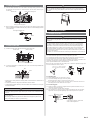
HEAT PUMP
OUTDOOR UNIT
INSTALLATION MANUAL
For authorized service personnel only.
PART No.9374995547
Contents
1. SAFETY PRECAUTIONS ..........................................................................................1
2. ABOUT THIS PRODUCT...........................................................................................2
3. GENERAL SPECIFICATIONS ...................................................................................3
4. INSTALLATION WORK ............................................................................................. 3
5. PIPE INSTALLATION ................................................................................................ 5
6. ELECTRICAL WIRING ..............................................................................................6
7. TEST RUN .................................................................................................................8
8. PUMP DOWN ............................................................................................................ 8
9. CUSTOMER GUIDANCE ..........................................................................................8
Installation must be performed in accordance with the requirement of NEC and CEC by
authorized service personnel only.

En-2
WARNING
Do not modify power cable, use extension cable or branch wiring. Improper use may
cause electric shock or ¿ re by poor connection, insuf¿ cient insulation or over current.
Do not purge the air with refrigerants but use a vacuum pump to vacuum the installation.
There is no extra refrigerant in the outdoor unit for air purging.
Using the same vacuum pump for different refrigerants may damage the vacuum pump
or the unit.
Use a clean gauge manifold, vacuum pump and charging hose for R410A exclusively.
This appliance is not intended for use by persons (including children) with reduced
physical, sensory or mental capabilities, or lack of experience and knowledge, unless
they have been given supervision or instruction concerning use of the appliance by a
person responsible for their safety. Children should be supervised to ensure that they
do not play with the appliance.
During the pump-down operation, make sure that the compressor is turned off before
you remove the refrigerant piping.
Do not remove the connection pipe while the compressor is in operation with 2 way or 3
way valve open. This may cause abnormal pressure in the refrigeration cycle that leads
to rupture and even injury.
CAUTION
This product must be installed by quali¿ ed personnel with a capacity certi¿ cation of
handling refrigerant À uids. Refer to regulation and laws in use on installation place.
Install the product by following local codes and regulations in force at the place of
installation, and the instructions provided by the manufacturer.
This product is part of a set constituting an air conditioner. The product must not be
installed alone or be installed with non-authorized device by the manufacturer.
To protect the persons, earth( ground) the unit correctly, and use the power cable
combined with an Earth Leakage Circuit Breaker (ELCB).
The products are not explosion proof, and therefore should not be installed in explosive
atmosphere.
This product contains no user-serviceable parts. Always consult experienced service
technicians for repairing.
When moving or relocating the air conditioner, consult experienced service technicians
for disconnection and reinstallation of the unit.
Do not place any other electrical products or household belongings under indoor unit or
outdoor unit. Condensation dripping from the unit might get them wet, and may cause
damage or malfunction of your property.
2. ABOUT THIS PRODUCT
• This product is manufactured to metric units and tolerances. United States customary
units are provided for reference only. In cases where exact dimensions and tolerances
are required, always refer to metric units.
2.1. Special tools for R410A refrigerant
WARNING
To install a unit that uses R410A refrigerant, use dedicated tools and piping materials
that have been manufactured speci¿ cally for R410A use. Because the pressure of
R410A refrigerant is approximately 1.6 times higher than R22, failure to use dedicated
piping material or improper installation can cause rupture or injury. Furthermore, it can
cause serious accidents such as water leakage, electric shock, or ¿ re.
Tool name
Contents of change
Gauge manifold
Pressure is high and cannot be measured with a conventional
gauge. To prevent erroneous mixing of other refrigerants, the
diameter of each port has been changed.
It is recommended the gauge with seals 30 in. Hg to 769 psi
(-0.1 to 5.3 MPa) for high pressure. 30 in. Hg to 551 psi (-0.1 to
3.8 MPa) for low pressure.
Charge hose
To increase pressure resistance, the hose material and base
size were changed.
Vacuum pump
A conventional vacuum pump can be used by installing a
vacuum pump adapter.
Be sure that the pump oil does not back À ow into the system.
Use one capable for vacuum suction of -100.7 kPa
(5 Ton, -755 mmHg).
Gas leakage
detector
Special gas leakage detector for HFC refrigerant R410A.
Copper pipes
It is necessary to use seamless copper pipes and it is desirable that the amount of re-
sidual oil is less than 40 mg/10 m. Do not use copper pipes having a collapsed, deformed
or discolored portion (especially on the interior surface). Otherwise, the expansion valve
or capillary tube may become blocked with contaminants.
As an air conditioner using R410A incurs pressure higher than when using conventional
refrigerant, it is necessary to choose adequate materials.
Thicknesses of copper pipes used with R410A are as shown in the table. Never use cop-
per pipes thinner than that in the table even when it is available on the market.
Thicknesses of Annealed Copper Pipes (R410A)
Pipe outside diameter [in. (mm)] Thickness [in. (mm)]
1/4 (6.35) 0.032 (0.80)
3/8 (9.52) 0.032 (0.80)
1/2 (12.70) 0.032 (0.80)
5/8 (15.88) 0.039 (1.00)
3/4 (19.05) 0.047 (1.20)
2.2. Accessories
The following installation accessories are supplied.
Use them as required.
Name and shape Q’ty Application
Installation
manual
1
(This book)
Drain cap
5
For outdoor unit drain
piping work
Drain pipe *1
1
Adapter [in. (mm)]
1/2 (12.70) ĺ 5/8 (15.88)
(18 MODEL only)
1
Adapter is necessary in the
connection of the indoor
unit. For more information,
refer to the installation
manual included with the
indoor unit.
Adapter [in. (mm)]
1/4 (6.35) ĺ 3/8 (9.52)
1
*1
Included only reverse cycle model.
One set of following parts are necessary installation of this product.
Name
Connection pipe assembly Decorative tape Saddle Tapping screws
Connection cable Vinyl tape Drain hose Sealant
Wall pipe Wall cap M10 bold, nut
2.3. Pipe length
Pipe length
Max. height
Max. Min.
164 ft. (50 m) 16 ft. (5 m) 98 ft. (30 m)
CAUTION
If the pipe lengths and height differences are not kept as shown in the table, correct
operation cannot be guaranteed.
The outdoor unit with the refrigerant removed from the packaging is sealed.
(Indoor unit, the refrigerant is not sealed.)

En-3
3.4. Additional charge
Refrigerant suitable for a piping length of 66ft (20m) is charged in the outdoor unit at the
factory.
When the piping is longer than 66ft (20m), additional charging is necessary.
For the additional amount, see the table below.
Piping length
66ft
(20m)
99ft
(30m)
131ft
(40m)
165ft
(50m)
Rate
Additional charge None
14.2oz
(400g)
1lb 12oz
(800g)
2lb 10oz
(1200g)
0.43oz/ft
(40g/m)
CAUTION
When adding refrigerant, add the refrigerant from the charging port at the completion
of work.
When moving and installing the air conditioner, do not mix gas other than the
speci¿ ed refrigerant R410A inside the refrigerant cycle.
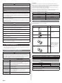
When charging the refrigerant R410A, always use an electronic balance for refrig-
erant charging (to measure the refrigerant by weight).
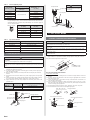
When charging the refrigerant, take into account the
slight change in the composition of the gas and liquid
phases, and always charge from the liquid phase side
whose composition is stable.
R410A
Liquid
Gas
Add refrigerant from the charging valve after the comple-
tion of the work.
If the units are further apart than the maximum pipe length, correct operation can-
not be guaranteed.
Gas leakage inspection
CAUTION
After connecting the piping, check the all joints for gas leakage with gas leak detector.
4. INSTALLATION WORK
4.1. Selecting an installation location
• Decide the mounting position with the customer as follows.
• Do not set to a place where there is oily smoke, oil is used in the factory, the unit can
contact sea breeze, sul¿ de gases will be generated in the hot spring area, corrosive
gases will be generated, animal may urine on the unit and ammonia will be generated
and a dusty place.
4.2. Installation dimensions
WARNING
Install at a place that can withstand the weight of the outdoor units and install positively
so that the units will not topple or fall.
Install the unit where it will not be tilted by more than 5°.
When installing the outdoor unit where it may exposed to strong wind, fasten it
securely.
CAUTION
Do not install where there is the danger of combustible gas leakage.
Do not install near heat sources.
If children may approach the unit, take preventive measures so that they cannot reach
the unit.
(1) If possible, do not install the unit where it will be exposed to direct sunlight.
(If necessary, Install a blind that does not interfere with the air À ow.)
(2) Do not install the unit where a strong wind blows or where it is very dusty.
(3) Do not install in an area that has heat sources, vapors, or the risk of leakage or
accumulation of À ammable gas.
(4) Do not install the unit where people pass.
(5) Take you neighbors into consideration so that they are not disturbed by air blowing
into their windows or by noise.
(6) Provide the space shown in ¿ gure so that the airÀ ow is not blocked. Also for ef¿ cient
operation, leave open three of the four directions front, rear, and both sides.
(7) Install the unit where keep away more than 3 m from the antenna of TV set and Radio.
(8) Outdoor unit should be set to a place where both drainage and itself will not be
affected when heating.
3. GENERAL SPECIFICATIONS
3.1. Power
WARNING
Always use a special branch circuit and install a special receptacle to supply power to
the room air conditioner.
Use a circuit breaker and receptacle matched to the capacity of the air conditioner.
Install a leakage circuit breaker in accordance with the related laws and regulations
and electric company standards.
The circuit breaker is installed in the permanent wiring. Always use a circuit that can
trip all the poles of the wiring and has an isolation distance of at least 3 mm between
the contacts of each pole.
CAUTION
The power source capacity must be the sum of the air conditioner current and the cur-
rent of other electrical appliances. When the current contracted capacity is insuf¿ cient,
change the contracted capacity.
When the voltage is low and the air conditioner is dif¿ cult to start, contact the power
company the voltage raised.
3.2. Selecting circuit breaker and wiring
CAUTION
Be sure to install a breaker of the speci¿ ed capacity.
Regulation of cables and breaker differs from each locality, refer in accordance with
local rules.
Voltage rating
1 ø 208/230 V (60 Hz)
Operating range
188-253 V
Cable Type Remarks
Power supply cable 14AWG
2 cable + Earth (Ground),
1 ø 208/230 V
Connection cable
14AWG
3 cable + Earth (Ground),
1 ø 208/230 V
Select the correct cable type and size according to the country or region’s regulations.
Max. wire length: Set a length so that the voltage drop is less than 2%. Increase the wire
diameter when the wire length is long.
CAUTION
Outdoor unit capacity 18 24 30 36
MINIMUM CIRCUIT AMPACITY 17 A 18 A 23.3 A 23.3 A
MAX. CKT. BKR.
20 A 30 A 30 A 30 A
• Before starting work check that power is not being supplied to all poles of the indoor
unit and outdoor unit.
• Install all electrical works in accordance to the national standard.
• Install the disconnect device with a contact gap of at least 3 mm in all poles nearby the
units. (Both indoor unit and outdoor unit)
• Install the circuit breaker nearby the units.
3.3. Operating range
Outdoor temperature
Cooling/Dry Mode
Model 18, 24 About -5 to 115 °F
Model 30, 36 About 14 to 115 °F
Heating Mode
Model 18, 24 About -5 to 75 °F
Model 30, 36 About 5 to 75 °F

En-4
4.2.1. Single outdoor unit installation
When the upper space is open:
[Unit: in. (mm)]
(1) Obstacles at the rear only
4 (100) or more
(2) Obstacles at the rear and sides
10 (250) or more
12 (300)
or more
4 (100)
or more
(3) Obstacles at the front only
24 (600) or more
(4) Obstacles at the front and rear
24 (600) or more
4 (100) or more
When an obstruction in the upper space:
[Unit: in. (mm)]
(1) Obstacles at the rear and above
12 (300)
or more
Max.20
(500)
24 (600)
or more
(2) Obstacles at the rear, sides, and above
40 (1000)
or more
4 (100)
or more
10 (250) or more
20 (500) or
more
Max. 20
(500)
4.2.2. Multiple outdoor unit installation
• Provide at least 10 in. (250 mm) of space between the outdoor units if multiple units are
installed.
• When routing the piping from the side of an outdoor unit, provide space for the piping.
• No more than 3 units must be installed side by side. When 3 units or more are arranged
in a line, provide the space as shown in the following example when an obstruction in
the upper space.
When the upper space is open:
[Unit: in. (mm)]
(1) Obstacles at the rear only
12 (300)
or more
10 (250)
or more
(2) Obstacles at the front only
60 (1500)
or more
10 (250)
or more
(3) Obstacles at the front and rear
20 (500) or more
10 (250) or more
60 (1500) or more
When an obstruction in the upper space:
[Unit: in. (mm)]
Obstacles at the rear and above
60 (15 00) or more
20 (500) or more
60 (1500) or more
Max. 12
(300)
10 (250) or more
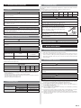
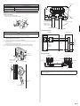
4.2.3. Outdoor units installation multi-row
[Unit: in. (mm)]
(1) Single parallel unit arrangement
6 (150) or more
24 (600) or more
60 (1500) or more
79 (2000) or more
(2) Multiple parallel unit arrangement
20 (500) or more
24 (600) or more
60 (1500) or more
10 (250) or more
119 (3000) or more
10 (250) or more
60 (1500)
or more
20 (500) or more
10 (250)
or more
NOTES:
• If the space is larger than stated above, the condition will be the same as when there is
no obstacle.
• Height above the À oor level should be 2 in. (50 mm) or more.
• When installing the outdoor unit, be sure to open the front and left side to obtain better
operation ef¿ ciency.

En-5
CAUTION
In area with heavy snowfall, if the inlet and outlet of the outdoor unit is blocked with
snow, it might become dif¿ cult to get warm, and it is likely to cause product malfunc-
tion. Construct a canopy and a pedestal, or place the unit on a high stand that is locally
installed.
5. PIPE INSTALLATION
5.1. Pipe connection
CAUTION
Fasten a À are nut with a torque wrench as instructed in this manual. If fastened too
tight, the À are nut may be broken after a long period of time and cause a leakage of
refrigerant.
Install heat insulation around both the gas and liquid pipes. Failure to do so may cause water leaks.
Use heat insulation with heat resistance above 248 °F. (Reverse cycle model only)
In addition, if the humidity level at the installation location of the refrigerant piping is
expected to exceed 70%, install heat insulation around the refrigerant piping. If the
expected humidity level is 70-80%, use heat insulation that is 15 mm or thicker and if
the expected humidity exceeds 80%, use heat insulation that is 20 mm or thicker.
If heat insulation is used that is not as thick as speci¿ ed, condensation may form on the
surface of the insulation.
In addition, use heat insulation with heat conductivity of 0.045 W/(m·K) or less (at 68 °F).
5.1.1. Flaring
(1) Cut the connection pipe to the necessary length with a pipe cutter.
(2)
Hold the pipe downward so that cuttings will not enter the pipe and remove the burrs.
(3) Insert the À are nut onto the pipe and À are the pipe with a À aring tool.
Insert the flare nut (always use the flare nut attached to the indoor and outdoor units
respectively) onto the pipe and perform the À are processing with a À are tool.
Use the special R410A À are tool, or the R22 À are tool.
When using the conventional À are tool, always use an allowance adjustment gauge and
secure the A dimension shown in table 1.
L
Check if [L] is flared uniformly
and is not cracked or scratched.
Pipe
A
B
Die
5.1.2. Bending pipes
(1) When bending the pipe, be careful not to crush it.
(2) To prevent breaking of the pipe, avoid sharp bends.
Bend the pipe with a radius of curvature of 70 mm or over.
(3) If the copper pipe is bend the pipe or pulled to often, it will become stiff. Do not
bend the pipes more than three times at one place.
5.1.3. Connecting pipes
(1) Install the outdoor unit wall cap (supplied with the optional installation set or pro-
cured at the site) to the wall pipe.
(2) Connect the outdoor unit and indoor unit piping.
(3) After matching the center of the À are surface and tightening the nut hand tight,
tighten the nut to the speci¿ ed tightening torque with a torque wrench. (Table 2)
Holding spanner
90°
Body side
Torque wrench
To prevent gas leakage, coat the À are
surface with refrigerator oil.
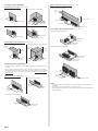
4.3. Drain installation
(1) Since the drain water À ows out of the outdoor unit during heating operation, install
the drain pipe and connect it to a commercial 5/8 in. (16 mm) hose. (Reverse cycle
model only)
Bottom side
Drain pipe mounting place
Drain cap mounting place
(2) When installing the drain pipe, plug all the holes other than the drain pipe mounting
hole in the bottom of the outdoor unit with putty so there is no water leakage. (Reverse
cycle model only)
Drain pipe mounting hole
Drain pipe
Base
4.4. Secure the unit
(1) Outdoor unit to be fasten with bolts at the four places without fail.
Bottom side [Unit: in. (mm)]
4-ø1/2 (ø12) hole
25-9/16
(650)
14-9/16
(370)
(2) Fix securely with bolts on a solid block. (Use 4 sets of commercially available M10
bolt, nut and washer.)
Bolt
Nut
Block
• Set the unit on a strong stand such as thing made of concrete blocks to minimize shock
and vibration.
• Do not directly install it on the ground, otherwise it will cause failure.
• To obtain better operation ef¿ ciency, when the outdoor unit is installed, be sure to open
the front and left side.
CAUTION
Do not install the outdoor unit in two-stage where the drain water could freeze.
Otherwise the drainage from the upper unit may form ice and cause a malfunction of the
lower unit.
When the outdoor temperature is 32 °F (0 °C) or less, do not use the accessory drain
pipe and drain cap.
If the drain pipe and drain cap are used, the drain water in the pipe may freeze in ex-
tremely cold climate. (For reverse cycle model only.)

En-6
Table 1 Flare nut tightening torque
Pipe outside
diameter [in. (mm)]
Dimension A [in. (mm)]
Dimension B
0
- 0.4
[in. (mm)]
Flare tool for R410A,
clutch type
1/4 (6.35)
0 to 0.020 (0 to 0.5)
3/8 (9.1)
3/8 (9.52) 1/2 (13.2)
1/2 (12.70) 5/8 (16.6)
5/8 (15.88) 3/4 (19.7)
3/4 (19.05) 15/16 (24.0)
• When using conventional À are tools to À are R410A pipes, the dimension A should
be approximately 0.020 in. (0.5 mm) more than indicated in the table (for À aring
with R410A À are tools) to achieve the speci¿ ed À aring. Use a thickness gauge to
measure the dimension A.
Pipe outside diameter
[in. (mm)]
Width across À ats of Flare nut
[in. (mm)]
1/4 (6.35) 11/16 (17)
3/8 (9.52) 7/8 (22)
1/2 (12.70) 1 (26)
5/8( 15.88) 1-1/8 (29)
3/4 (19.05) 1-7/16 (36)
Width across À ats
Table 2 Pipe outside diameter
Flare nut [in. (mm)] Tightening torque [lbf·ft. (N·m)]
1/4 (6.35) dia. 11.8 to 13.3 (16 to 18)
3/8 (9.52) dia. 23.6 to 31.0 (32 to 42)
1/2 (12.70) dia. 36.1 to 45.0 (49 to 61)
5/8 (15.88) dia. 46.5 to 55.3 (63 to 75)
3/4 (19.05) dia. 66.4 to 81.1 (90 to 110)
5.2. Vacuum process
CAUTION
Do not purge the air with refrigerants, but use a vacuum pump to vacuum the
installation.
There is no extra refrigerant in the outdoor unit for air purging.
Use a vacuum pump and gauge manifold and charging hose for R410A exclusively.
Using the same vacuum for different refrigerants may damage the vacuum pump or the
unit.
(1) Remove the cap, and connect the gauge manifold and the vacuum pump to the
charging valve by the service hoses.
(2) Vacuum the indoor unit and the connecting pipes until the pressure gauge indi-
cates 76 cmHg (-0.1 MPa).
(3) When 76 cmHg (-0.1 MPa) is reached, operate the vacuum pump for at least 60
minutes.
(4) Disconnect the service hoses and ¿ t the cap to the charging valve to the speci¿ ed
torque.
(5) Remove the blank caps, and fully open the spindles of the 3-way (Liquid) and 3-way
(Gas) valves with a hexagon wrench [Torque: 60 to 70 kgf·cm (6 to 7 N·m)].
(6) Tighten the blank caps of the 3-way (Liquid) valve and 3-way (Gas) valve to the
speci¿ ed torque.
Tightening torque [lbt·ft (N·m)]
Blank cap
3/8 in. (9.52 mm) 14.8 to 18.4 (20 to 25)
5/8 in. (15.88 mm) 22.1 to 25.8 (30 to 35)
Charging port cap
9.2 to 11.8 (12.5 to 16)
Blank cap
Charging port
Cap
Service hose
with valve core
Outdoor unit
3-way valve
Connecting pipe
Hexagon wrench
Use a 4 mm
hexagon wrench.
Lo
Hi
Service hose
Gauge manifold
Vacuum pump
CAUTION
Use a clean gauge manifold
and charging hose for R410A
exclusively.
6. ELECTRICAL WIRING
6.1. How to connect the wire to the terminals
CAUTION
Match the terminal block numbers and connection cable colors with those of the outdoor
unit or branch box. Incorrect wiring may cause a ¿ re.
Connect the connection cables ¿ rmly to the terminal block. Imperfect installation may
cause a ¿ re.
When ¿ xing the connection cable with the cable clamp, always fasten the cable at the
plastic jacket portion, but not at the insulator portion. If the insulator is chafed, electric
leakage may occur.
Do not use an earth screw for an external connector. Only use for interconnection
between two units.
• When stripping off the coating of a lead wire, always use a special tool such as a wire
stripper. If there is no special tool available, carefully strip the coating with a knife etc.
1-3/16 in. (30 mm)
Keep the earth wire longer than the other wires.
Power supply cable
or connection cable
Earth wire
1-9/16 in. (40 mm)
or more
How to connect wiring to the terminal
Caution when wiring cable
(1) Use ring terminals with insulating sleeves as shown in the ¿ gure below to connect to
the wire.
(2) Securely crimp the ring terminals to the wires using an appropriate tool so that the
wires do not come loose.
(3) Use the speci¿ ed wires, connect them securely, and fasten them so that there is no
stress placed on the terminals.
(4) Use an appropriate screwdriver to tighten the terminal screws. Do not use a screw-
driver that is too small, otherwise, the screw heads may be damaged and prevent the
screws from being properly tightened.
(5) Do not tighten the terminal screws too much, otherwise, the screws may break.
(6) See the table below for the terminal screw tightening torques.
Sleeve
Strip : 3/8 in. (10 mm)
Ring type terminal
Wire
Screw with special washer
Ring type terminal
Terminal blocks
Screw with special washer
Wire
Ring type terminal

En-7
Tightening torque [lbf·in. (N·m)]
M3.5 screw 7.1 to 8.9 (0.8 to 1.0)
M4 screw 10.6 to 15.9 (1.2 to 1.8)
M5 screw 17.7 to 26.5 (2.0 to 3.0)
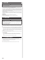
6.2. Wiring method
Valve cover removal
•
Remove the one mounting screw.
• Remove the valve cover by sliding upward
Hook (4 places)
Valve cover
CAUTION
When connecting the power supply cable, make sure that the phase of the power
supply matches with the phase of the terminal board. If the phases do not match, the
compressor will rotate in reverse and will not be able to compress.
(1) Service cover removal
•
Remove the two mounting screws
•
Remove the service cover by pushing downwards.
(2) Fasten the power supply cable and the connection cable to the conduit holder
using the lock nut.
(open the knock out holes if necessary)
(3) Connect the power supply cable and the connection cable to terminal.
(4) Fasten the power supply cable and connection cable with cable clamp.
Direction of the
service panel
removal
Service cover
Hook
(3 places)
Inter-unit
line
Power supply
Lock
nut
GG
Terminal
Control box
Cable clamp
Connection cable
(indoor unit and
outdoor unit con-
nection cable)
Power supply cable
Connection diagrams
1
2
3
1
2
3
GG
L1
L2
INDOOR
Power supply line Single-
phase, 230/208 V
INDOOR UNIT
DISCON-
NECT
SWITCH
(Locally
procured )
TERMINAL
OUTDOOR UNIT
TERMINAL
Power lines
Control line
Grounding line
Wiring procedure
G
12
3
4
12
3
L1 L2
G
G
Indoor unit
terminal block
Outdoor unit
terminal block
Earth screw
Disconnect switch
Earth screw
Earth screw
Power supply line
NOTE:
Factory installed protective inline fuses for indoor units’ conductors are installed on the
Power Supply PCB.

En-8
7. TEST RUN
CAUTION
Always turn on the power 12 hours prior to the start of the operation in order to
ensure compressor protection.
x
Perform test operation and check items below.
x
For the test operation method, refer to the operating manual.
x
The outdoor unit, may not operate, depending on the room temperature. In this
case, keep on pressing the MANUAL AUTO button of the indoor unit for more than
10 seconds. The operation indicator lamp and timer indicator lamp will begin to À ash
simultaneously during cooling test run. Then, heating test run will begin in about three
minutes when HEAT is selected by the remote control operation. (Please follow the
operating manual for remote control operation.)
x
To end test operation, keep on pressing the MANUAL AUTO button of the indoor unit for
more than 3 seconds.
(When the air conditioner is run by pressing the MANUAL AUTO button, the OPERA-
TION indicator lamp and TIMER indicator lamp of the indoor unit will simultaneously
À ash slowly.)
OUTDOOR UNIT
(1) Is there any abnormal noise and vibration during operation?
(2) Will noise, wind, or drain water from the unit disturb the neighbors?
(3) Is there any gas leakage?
8. PUMP DOWN
CAUTION
Please check the refrigerant circuit for any leaks before starting the pump down
operation.
Do not proceed with the pump down operation if there is no refrigerant left in the
circuit due to bent or broken piping
During the pump down operation, be sure to turn off the compressor before
removing the refrigerant piping.
PUMP DOWN OPERATION (FORCED COOLING OPERATION)
To avoid discharging refrigerant into the atmosphere at the time of relocation or disposal,
recover refrigerant by doing the forced cooling operation according to the following proce-
dure.
(1) Conduct preliminary operation for 5 to 10 minutes using the forced cooling operation.
Start the forced cooling operation. Keep on pressing the MANUAL AUTO button of the
indoor unit for more than 10 seconds. The operation indicator lamp and timer indicator
lamp will begin to flash simultaneously during test run. (The forced cooling operation
cannot start if the MANUAL AUTO button is not kept on pressing for more than 10 sec-
onds.)
(2) Close the valve stem of 2-way valve completely.
(3) Continue the forced cooling operation for 2 to 3 minutes, then close all the valve stems
on the 3-way valves
(4) Stop the operation.
• Press the START/STOP button of the remote controller to stop the operation.
• Press the MANUAL AUTO button when stopping the operation from the indoor unit
side.
(It is not necessary to press down for more than 10 seconds.)
9. CUSTOMER GUIDANCE
Explain the following to the customer in accordance with the operating manual:
(1) Starting and stopping method, operation switching, temperature adjustment, timer, air
À ow adjustment, and other remote control unit operations.
(2) Air ¿ lter removal and cleaning.
(3) Give the operating manual and installation instruction sheet to the customer.
-
 1
1
-
 2
2
-
 3
3
-
 4
4
-
 5
5
-
 6
6
-
 7
7
-
 8
8


Fujitsu ROSH36AXJ Guide d'installation
- Taper
- Guide d'installation
- Ce manuel convient également à
dans d''autres langues
- English: Fujitsu ROSH36AXJ Installation guide
Documents connexes
-
Fujitsu UOSH15AHWJ Guide d'installation
-
-
-
Fujitsu ASGA30FUTC-B Guide d'installation
-
Fujitsu AOU48RLXFZ1 Guide d'installation
-
-
-
Fujitsu ASAG07LMCA Guide d'installation
-
-